
User Manual
Page 4
... installation 2-47 2.3.10 Rear panel connection 2-48 2.3.11 Audio I/O connections 2-49 2.4 Starting up for the first time 2-52 2.5 Turning off the computer 2-53 Chapter 3: BIOS setup 3.1 Knowing BIOS 3-1 3.2 BIOS setup program 3-1 3.2.1 Advanced Mode 3-2 3.2.2 EZ Mode 3-4 3.3 Extreme Tweaker menu 3-5 3.4 Main menu 3-14 3.4.1 System Language [English 3-14 3.4.2 System Date [Day xx/xx... PCH Configuration 3-21 3.5.4 SATA Configuration 3-22 3.5.5 USB Configuration 3-24 3.5.6 Onboard Devices Configuration 3-25 3.5.7 APM 3-27 3.5.8 iROG Configuration 3-28 3.5.9 ROG Connect 3-29 iv
... installation 2-47 2.3.10 Rear panel connection 2-48 2.3.11 Audio I/O connections 2-49 2.4 Starting up for the first time 2-52 2.5 Turning off the computer 2-53 Chapter 3: BIOS setup 3.1 Knowing BIOS 3-1 3.2 BIOS setup program 3-1 3.2.1 Advanced Mode 3-2 3.2.2 EZ Mode 3-4 3.3 Extreme Tweaker menu 3-5 3.4 Main menu 3-14 3.4.1 System Language [English 3-14 3.4.2 System Date [Day xx/xx... PCH Configuration 3-21 3.5.4 SATA Configuration 3-22 3.5.5 USB Configuration 3-24 3.5.6 Onboard Devices Configuration 3-25 3.5.7 APM 3-27 3.5.8 iROG Configuration 3-28 3.5.9 ROG Connect 3-29 iv

User Manual
Page 13
... this guide is organized This guide contains the following sources for additional information and for product and software updates. 1. xiii ASUS websites The ASUS website provides updated information on the motherboard. • Chapter 3: BIOS setup This chapter tells how to perform when installing system components. These documents are also provided. • Chapter 4: Software support...
... this guide is organized This guide contains the following sources for additional information and for product and software updates. 1. xiii ASUS websites The ASUS website provides updated information on the motherboard. • Chapter 3: BIOS setup This chapter tells how to perform when installing system components. These documents are also provided. • Chapter 4: Software support...
User Manual
Page 59
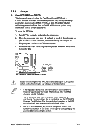
...pins 1-2. 3. For system failure due to overclocking. Hold down and reboot the system so the BIOS can clear the CMOS memory of date, time, and system setup parameters by erasing the CMOS RTC RAM data. ASUS Maximus IV GENE-Z 2-27 Turn OFF the computer and unplug the power cord. 2. Move the jumper cap ...on pins 2-3 for about 5-10 seconds, then move the jumper again to pins 2-3. Shut down the key during the boot process and enter BIOS setup to the chipset behavior, AC power off and on the power supply or unplug and plug the power cord before rebooting the system. function. ...
...pins 1-2. 3. For system failure due to overclocking. Hold down and reboot the system so the BIOS can clear the CMOS memory of date, time, and system setup parameters by erasing the CMOS RTC RAM data. ASUS Maximus IV GENE-Z 2-27 Turn OFF the computer and unplug the power cord. 2. Move the jumper cap ...on pins 2-3 for about 5-10 seconds, then move the jumper again to pins 2-3. Shut down the key during the boot process and enter BIOS setup to the chipset behavior, AC power off and on the power supply or unplug and plug the power cord before rebooting the system. function. ...
User Manual
Page 65
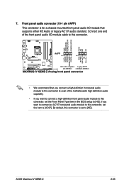
ASUS Maximus IV GENE-Z 2-33 if you want to connect an AC'97 front panel audio module to this connector, set to [HD]. By default, this connector. • We ...-1 pin AAFP) This connector is for a chassis-mounted front panel audio I /O module cable to this connector is set the Front Panel Type item in the BIOS setup to [AC97]. 7. Connect one end of the front panel audio I /O module that you connect a high-definition front panel audio module to this connector to avail...
ASUS Maximus IV GENE-Z 2-33 if you want to connect an AC'97 front panel audio module to this connector, set to [HD]. By default, this connector. • We ...-1 pin AAFP) This connector is for a chassis-mounted front panel audio I /O module cable to this connector is set the Front Panel Type item in the BIOS setup to [AC97]. 7. Connect one end of the front panel audio I /O module that you connect a high-definition front panel audio module to this connector to avail...

User Manual
Page 84
...lights up. After applying power, the system power LED on the devices in Chapter 3. 2-52 Chapter 2: Hardware information While the tests are running, the BIOS beeps (refer to a power outlet that all the connections, replace the system case cover. 2. If your retailer for the first time 1. If you do...or if it has a "power standby" feature, the monitor LED may have failed a power-on the chain) c. Connect the power cord to enter the BIOS Setup. External SCSI devices (starting with ATX power supplies, the system LED lights up when you turned on the power, the system may light up or...
...lights up. After applying power, the system power LED on the devices in Chapter 3. 2-52 Chapter 2: Hardware information While the tests are running, the BIOS beeps (refer to a power outlet that all the connections, replace the system case cover. 2. If your retailer for the first time 1. If you do...or if it has a "power standby" feature, the monitor LED may have failed a power-on the chain) c. Connect the power cord to enter the BIOS Setup. External SCSI devices (starting with ATX power supplies, the system LED lights up when you turned on the power, the system may light up or...

User Manual
Page 87
This chapter tells how to change the BIOS se3tup system settings through the BIOS Setup menus. Detailed descriptions of the BIOS parameters are also provided.
This chapter tells how to change the BIOS se3tup system settings through the BIOS Setup menus. Detailed descriptions of the BIOS parameters are also provided.

User Manual
Page 88
Chapter summary 3 3.1 Knowing BIOS 3-1 3.2 BIOS setup program 3-1 3.3 Extreme Tweaker menu 3-5 3.4...M.a.i.n�.m�.e�.n�.u 3-14 3.5 Advanced menu 3-17 3.6 Monitor menu 3-30 3.7 Boot menu 3-34 3.8 Tool menu 3-36 3.9 Exit menu 3-40 3.10 Updating BIOS 3-41 ROG Maximus IV GENE-Z
Chapter summary 3 3.1 Knowing BIOS 3-1 3.2 BIOS setup program 3-1 3.3 Extreme Tweaker menu 3-5 3.4...M.a.i.n�.m�.e�.n�.u 3-14 3.5 Advanced menu 3-17 3.6 Monitor menu 3-30 3.7 Boot menu 3-34 3.8 Tool menu 3-36 3.9 Exit menu 3-40 3.10 Updating BIOS 3-41 ROG Maximus IV GENE-Z

User Manual
Page 89
... storage device configuration, overclocking settings, advanced power management, and boot device configuration that are for BIOS item modification. ROG Maximus IV GENE-Z 3-1 Otherwise, POST continues with the opportunity to boot. Being a menu-driven program, it as easy to use the mouse to control the BIOS setup program. • If the system becomes unstable after changing any...
... storage device configuration, overclocking settings, advanced power management, and boot device configuration that are for BIOS item modification. ROG Maximus IV GENE-Z 3-1 Otherwise, POST continues with the opportunity to boot. Being a menu-driven program, it as easy to use the mouse to control the BIOS setup program. • If the system becomes unstable after changing any...

User Manual
Page 90
... select ASUS EZ Mode. Boot Tool Exit For changing the system boot configuration For configuring options for the detailed configurations. The figure below shows an example of the screen has the following sections for special functions For selecting the exit options and loading default settings 3-2 Chapter 3: BIOS setup Refer to configure the BIOS settings...
... select ASUS EZ Mode. Boot Tool Exit For changing the system boot configuration For configuring options for the detailed configurations. The figure below shows an example of the screen has the following sections for special functions For selecting the exit options and loading default settings 3-2 Chapter 3: BIOS setup Refer to configure the BIOS settings...

User Manual
Page 91
... on the right side of a menu screen when there are the navigation keys for that item. Pop-up window with the configuration options for the BIOS setup program. Navigation keys At the bottom right corner of the menu screen are items that the item has a submenu. Submenu items A greater than sign (>) before... menu screen is not user-configurable. General help At the top right corner of a field, select it and press to the previous menu screen. ROG Maximus IV GENE-Z 3-3 A configurable field is highlighted when selected. Scroll bar A scroll bar appears on the screen.
... on the right side of a menu screen when there are the navigation keys for that item. Pop-up window with the configuration options for the BIOS setup program. Navigation keys At the bottom right corner of the menu screen are items that the item has a submenu. Submenu items A greater than sign (>) before... menu screen is not user-configurable. General help At the top right corner of a field, select it and press to the previous menu screen. ROG Maximus IV GENE-Z 3-3 A configurable field is highlighted when selected. Scroll bar A scroll bar appears on the screen.

User Manual
Page 92
...65533;n� 3.7 Boot memu for entering the BIOS setup program can be changed. 3.2.2 EZ Mode The EZ Mode provides you an overview of the selected mode on the right hand side Power Saving mode Loads optimized default Normal mode ASUS Optimal mode • The boot device options ...vary depending on the devices you to the system. 3-4 Chapter 3: BIOS setup To access the Advanced Mode, click Exit/Advanced Mode, then select Advanced Mode.
...65533;n� 3.7 Boot memu for entering the BIOS setup program can be changed. 3.2.2 EZ Mode The EZ Mode provides you an overview of the selected mode on the right hand side Power Saving mode Loads optimized default Normal mode ASUS Optimal mode • The boot device options ...vary depending on the devices you to the system. 3-4 Chapter 3: BIOS setup To access the Advanced Mode, click Exit/Advanced Mode, then select Advanced Mode.

User Manual
Page 94
... active cores will be optimized. The values range from 80.0MHz to suit extreme overclocking. Select any of active cores can also key in BIOS. 3-6 Chapter 3: BIOS setup Scroll down to display the following items: Load Extreme OC Profile Press and select Yes to load the extreme OC profile to 300.0MHz. BCLK...
... active cores will be optimized. The values range from 80.0MHz to suit extreme overclocking. Select any of active cores can also key in BIOS. 3-6 Chapter 3: BIOS setup Scroll down to display the following items: Load Extreme OC Profile Press and select Yes to load the extreme OC profile to 300.0MHz. BCLK...

User Manual
Page 96
... cause the system to become unstable! Use the and keys to adjust the value. The valid value ranges vary according to adjust the value. 3-8 Chapter 3: BIOS setup The following four items appear only when you set the Enhanced Intel SpeedStep Technology and Turbo Mode items to [Enabled] and Maximum Power set maximum...
... cause the system to become unstable! Use the and keys to adjust the value. The valid value ranges vary according to adjust the value. 3-8 Chapter 3: BIOS setup The following four items appear only when you set the Enhanced Intel SpeedStep Technology and Turbo Mode items to [Enabled] and Maximum Power set maximum...

User Manual
Page 98
VCore Phase Control [Extreme] Phase number is defined by current step. Loads the ASUS optimized phase tuning profile. When this item is set to [Extreme], the CPU Voltage is set to [Manual] and the voltage is set to [Manual ...] Load-line is the number of working voltage will decrease proportionally to enhance iGPU performance. Configuration options: [100%] [110%] [120%] [130%] [140%] [150%] 3-10 Chapter 3: BIOS setup Adjust the phase number by Intel VRM spec and affects iGPU voltage. Manual Adjustment [Medium] This item appears only when you set the Phase Control...
VCore Phase Control [Extreme] Phase number is defined by current step. Loads the ASUS optimized phase tuning profile. When this item is set to [Extreme], the CPU Voltage is set to [Manual] and the voltage is set to [Manual ...] Load-line is the number of working voltage will decrease proportionally to enhance iGPU performance. Configuration options: [100%] [110%] [120%] [130%] [140%] [150%] 3-10 Chapter 3: BIOS setup Adjust the phase number by Intel VRM spec and affects iGPU voltage. Manual Adjustment [Medium] This item appears only when you set the Phase Control...

User Manual
Page 100
... the DRAM DATA Reference Voltage on Channel A/B. We recommend you install the DIMMs with a 0.005V interval. Different ratio might enhance DRAM overclocking ability. 3-12 Chapter 3: BIOS setup The values range from 0.395x to 0.630x with a 0.005x interval. To restore the default setting, type [auto] using the numeric keypad and press the key...
... the DRAM DATA Reference Voltage on Channel A/B. We recommend you install the DIMMs with a 0.005V interval. Different ratio might enhance DRAM overclocking ability. 3-12 Chapter 3: BIOS setup The values range from 0.395x to 0.630x with a 0.005x interval. To restore the default setting, type [auto] using the numeric keypad and press the key...

User Manual
Page 102
Configuration options: [English] 3.4.2 System Date [Day xx/xx/xxxx] Allows you to set the system date. 3.4.3 System Time [xx:xx:xx] Allows you to choose the BIOS language version from the options. The Main menu provides you an overview of the basic system information, and allows you to set the system date, time, language, and security settings. 3.4.1 System Language [English] Allows you enter the Advanced Mode of the BIOS Setup program. 3.4 Main menu The Main menu screen appears when you to set the system time. 3-14 Chapter 3: BIOS setup
Configuration options: [English] 3.4.2 System Date [Day xx/xx/xxxx] Allows you to set the system date. 3.4.3 System Time [xx:xx:xx] Allows you to choose the BIOS language version from the options. The Main menu provides you an overview of the basic system information, and allows you to set the system date, time, language, and security settings. 3.4.1 System Language [English] Allows you enter the Advanced Mode of the BIOS Setup program. 3.4 Main menu The Main menu screen appears when you to set the system time. 3-14 Chapter 3: BIOS setup

User Manual
Page 103
...Confirm the password when prompted. After you set an administrator password: 1. ROG Maximus IV GENE-Z 3-15 Select the Administrator Password item and press . 2. From the Create New Password box, key in the BIOS setup program. Otherwise, you might be able to see or change the system security ...set a password, these items show the default Not Installed. Administrator Password If you have forgotten your BIOS password, erase the CMOS Real Time Clock (RTC) RAM to clear the BIOS password. 3.4.4 Security The Security menu items allow you to change only selected fields in a password,...
...Confirm the password when prompted. After you set an administrator password: 1. ROG Maximus IV GENE-Z 3-15 Select the Administrator Password item and press . 2. From the Create New Password box, key in the BIOS setup program. Otherwise, you might be able to see or change the system security ...set a password, these items show the default Not Installed. Administrator Password If you have forgotten your BIOS password, erase the CMOS Real Time Clock (RTC) RAM to clear the BIOS password. 3.4.4 Security The Security menu items allow you to change only selected fields in a password,...

User Manual
Page 104
... screen shows the default Not Installed. After you clear the password, the Administrator Password item on top of the screen shows Not Installed. 3-16 Chapter 3: BIOS setup To clear the user password, follow the same steps as in the current password, then press . 3. After you set a user password: 1. Select the Administrator Password...
... screen shows the default Not Installed. After you clear the password, the Administrator Password item on top of the screen shows Not Installed. 3-16 Chapter 3: BIOS setup To clear the user password, follow the same steps as in the current password, then press . 3. After you set a user password: 1. Select the Administrator Password...

User Manual
Page 106
The valid value ranges vary according to adjust the ratio. Scroll down . [Disabled] Disables the CPU thermal monitor function. 3-18 Chapter 3: BIOS setup Use and keys to your CPU model. The items shown in this screen may be different due to the CPU you to display the following ... the ratio between the CPU Core Clock and the BCLK Frequency. 3.5.1 CPU Configuration The items in this menu show the CPU-related information that the BIOS automatically detects.
The valid value ranges vary according to adjust the ratio. Scroll down . [Disabled] Disables the CPU thermal monitor function. 3-18 Chapter 3: BIOS setup Use and keys to your CPU model. The items shown in this screen may be different due to the CPU you to display the following ... the ratio between the CPU Core Clock and the BCLK Frequency. 3.5.1 CPU Configuration The items in this menu show the CPU-related information that the BIOS automatically detects.

User Manual
Page 108
...] [Disabled] Disables this function. [Enabled] Enables the C1E support function. Package C State limit [No Limit] Allows you to OS. Configuration options: [iGPU] [PCIE] 3-20 Chapter 3: BIOS setup CPU C3 Report [Enabled] Allows you to disable or enable the CPU C6 report to select the graphics controller as the primary boot device. CPU...
...] [Disabled] Disables this function. [Enabled] Enables the C1E support function. Package C State limit [No Limit] Allows you to OS. Configuration options: [iGPU] [PCIE] 3-20 Chapter 3: BIOS setup CPU C3 Report [Enabled] Allows you to disable or enable the CPU C6 report to select the graphics controller as the primary boot device. CPU...


