
M5A97 LE R2.0 User's Manual
Page 1
Motherboard M5A97 LE R2.0
Motherboard M5A97 LE R2.0

M5A97 LE R2.0 User's Manual
Page 3
... About this guide...vii M5A97 LE R2.0 specifications summary ix Package contents...xii Installation tools and components xiii Product introduction 1.1 Special features 1-1 1.1.1 Product highlights 1-1 1.1.2 DIP (Dual Intelligent Processors) - TPU (TurboV Processing Unit) & EPU (Energy Processing Unit 1-2 1.1.3 ASUS Exclusive Features 1-2 1.1.4 ASUS Quiet Thermal Solution 1-3 1.1.5 ASUS EZ DIY 1-3 1.1.6 Other special features 1-4 1.2 Motherboard overview 1-5 1.2.1 Before you proceed 1-5 1.2.2 Motherboard layout 1-6 1.2.3 Central Processing...
... About this guide...vii M5A97 LE R2.0 specifications summary ix Package contents...xii Installation tools and components xiii Product introduction 1.1 Special features 1-1 1.1.1 Product highlights 1-1 1.1.2 DIP (Dual Intelligent Processors) - TPU (TurboV Processing Unit) & EPU (Energy Processing Unit 1-2 1.1.3 ASUS Exclusive Features 1-2 1.1.4 ASUS Quiet Thermal Solution 1-3 1.1.5 ASUS EZ DIY 1-3 1.1.6 Other special features 1-4 1.2 Motherboard overview 1-5 1.2.1 Before you proceed 1-5 1.2.2 Motherboard layout 1-6 1.2.3 Central Processing...

M5A97 LE R2.0 User's Manual
Page 6
... shock hazard, disconnect the power cable from the electrical outlet before relocating the system. • When adding or removing devices to or from the motherboard, ensure that all cables are correctly connected and the power cables are not damaged. Operation safety • Before installing the... motherboard and adding devices on a stable surface. • If you add a device. • Before connecting or removing signal cables from the system, ensure that the ...
... shock hazard, disconnect the power cable from the electrical outlet before relocating the system. • When adding or removing devices to or from the motherboard, ensure that all cables are correctly connected and the power cables are not damaged. Operation safety • Before installing the... motherboard and adding devices on a stable surface. • If you add a device. • Before connecting or removing signal cables from the system, ensure that the ...
M5A97 LE R2.0 User's Manual
Page 7
...Software support This chapter describes the contents of the switches, jumpers, and connectors on ASUS hardware and software products. It includes description of the support DVD that comes with the motherboard package and the software. • Chapter 5: RAID support This chapter describes the ... support This chapter describes how to install and configure multiple AMD® CrossFireX™ graphics cards. ASUS websites The ASUS website provides updated information on the motherboard. • Chapter 2: Basic Installation This chapter lists the hardware setup procedures that may have to ...
...Software support This chapter describes the contents of the switches, jumpers, and connectors on ASUS hardware and software products. It includes description of the support DVD that comes with the motherboard package and the software. • Chapter 5: RAID support This chapter describes the ... support This chapter describes how to install and configure multiple AMD® CrossFireX™ graphics cards. ASUS websites The ASUS website provides updated information on the motherboard. • Chapter 2: Basic Installation This chapter lists the hardware setup procedures that may have to ...

M5A97 LE R2.0 User's Manual
Page 9
..., AMD 100 Series CPUs support up to DDR3 1333MHz. • When you are using a Windows® 32-bit operating system. • Refer to www.asus.com for the latest Memory QVL (Qualified Vendors List). 2 x PCIe 2.0 x16 slots (Blue @x16 speed, Black @x4 speed) 2 x PCIe 2.0 x1...) (continued on the next page) ix With ASUS design, this motherboard can support up to 8-core Compatible with RAID 0, 1, 5 and 10 support Realtek® 8111F Gigabit LAN controller Realtek® ALC887 8-channel High Definition Audio CODEC - M5A97 LE R2.0 specifications summary CPU Chipset System Bus Memory Expansion...
..., AMD 100 Series CPUs support up to DDR3 1333MHz. • When you are using a Windows® 32-bit operating system. • Refer to www.asus.com for the latest Memory QVL (Qualified Vendors List). 2 x PCIe 2.0 x16 slots (Blue @x16 speed, Black @x4 speed) 2 x PCIe 2.0 x1...) (continued on the next page) ix With ASUS design, this motherboard can support up to 8-core Compatible with RAID 0, 1, 5 and 10 support Realtek® 8111F Gigabit LAN controller Realtek® ALC887 8-channel High Definition Audio CODEC - M5A97 LE R2.0 specifications summary CPU Chipset System Bus Memory Expansion...

M5A97 LE R2.0 User's Manual
Page 12
xii Actual product specifications may vary with different models. Package contents Check your motherboard package for the following items. M5A97 LE R2.0 ASUS M5A97 LE R2.0 motherboard SOCKET AM3+ User Manual User Guide Support DVD 2 x Serial ATA 6.0 Gb/s cables 1 x ASUS I/O Shield • If any of the above items is damaged or missing, contact your retailer. • The illustrated items above are for reference only.
xii Actual product specifications may vary with different models. Package contents Check your motherboard package for the following items. M5A97 LE R2.0 ASUS M5A97 LE R2.0 motherboard SOCKET AM3+ User Manual User Guide Support DVD 2 x Serial ATA 6.0 Gb/s cables 1 x ASUS I/O Shield • If any of the above items is damaged or missing, contact your retailer. • The illustrated items above are for reference only.

M5A97 LE R2.0 User's Manual
Page 13
Installation tools and components 1 bag of screws Philips (cross) screwdriver PC chassis Power supply unit AMD AM3+ CPU AMD AM3+ compatible CPU Fan DIMM SATA hard disk drive SATA optical disc drive (optional) Graphics card (optional) The tools and components in the table above are not included in the motherboard package. xiii
Installation tools and components 1 bag of screws Philips (cross) screwdriver PC chassis Power supply unit AMD AM3+ CPU AMD AM3+ compatible CPU Fan DIMM SATA hard disk drive SATA optical disc drive (optional) Graphics card (optional) The tools and components in the table above are not included in the motherboard package. xiii

M5A97 LE R2.0 User's Manual
Page 15
...motherboard also supports AMD® CPUs in the new 32nm manufacturing process. AMD® SB950 Chipset The AMD® SB950 Southbridge natively supports the next generation SATA 6.0 Gb/s data transfer rate and PCI Express 2.0 interface. CrossFireX™ allows higher antialiasing, anisotropic filtering, shading, and texture settings. M5A97 LE R2... AMD® FX™Series/Phenom™ II/Athlon™ II/Sempron™ 100 series CPU support This motherboard supports AMD® Socket AM3+ multi-core processors with unique L3 cache and delivers better overclocking capabilities with USB ...
...motherboard also supports AMD® CPUs in the new 32nm manufacturing process. AMD® SB950 Chipset The AMD® SB950 Southbridge natively supports the next generation SATA 6.0 Gb/s data transfer rate and PCI Express 2.0 interface. CrossFireX™ allows higher antialiasing, anisotropic filtering, shading, and texture settings. M5A97 LE R2... AMD® FX™Series/Phenom™ II/Athlon™ II/Sempron™ 100 series CPU support This motherboard supports AMD® Socket AM3+ multi-core processors with unique L3 cache and delivers better overclocking capabilities with USB ...

M5A97 LE R2.0 User's Manual
Page 18
Profile The motherboard features the ASUS O.C. feature automatically restores the CPU default settings when the system hangs due to conveniently store or load multiple BIOS settings. Profile that allows you the ... line with ASUS vision of the product and thus mitigate environmental impacts. Precision Tweaker 2 Allows you to fine-tune the VCore / VDDNB voltage in 0.00625V steps and DRAM voltage in 0.00625V steps to achieve the most precise setting for the ultimate overclocking configuration. 1.1.6 Other special features ErP ready The motherboard is in...
Profile The motherboard features the ASUS O.C. feature automatically restores the CPU default settings when the system hangs due to conveniently store or load multiple BIOS settings. Profile that allows you the ... line with ASUS vision of the product and thus mitigate environmental impacts. Precision Tweaker 2 Allows you to fine-tune the VCore / VDDNB voltage in 0.00625V steps and DRAM voltage in 0.00625V steps to achieve the most precise setting for the ultimate overclocking configuration. 1.1.6 Other special features ErP ready The motherboard is in...

M5A97 LE R2.0 User's Manual
Page 19
... you install or remove any component, switch off the ATX power supply and detach its power cord. 1.2 Motherboard overview 1.2.1 Before you proceed Take note of the following precautions before you install motherboard components or change any motherboard settings. • Unplug the power cord from the wall socket before touching any component. • Before... or a metal object, such as the power supply case, to avoid damaging them due to static electricity. • Hold components by the edges to the motherboard, peripherals, or components. Chapter 1 M5A97 LE R2.0 1-5
... you install or remove any component, switch off the ATX power supply and detach its power cord. 1.2 Motherboard overview 1.2.1 Before you proceed Take note of the following precautions before you install motherboard components or change any motherboard settings. • Unplug the power cord from the wall socket before touching any component. • Before... or a metal object, such as the power supply case, to avoid damaging them due to static electricity. • Hold components by the edges to the motherboard, peripherals, or components. Chapter 1 M5A97 LE R2.0 1-5

M5A97 LE R2.0 User's Manual
Page 20
Chapter 1 1-6 Chapter 1: Product introduction 1.2.2 Motherboard layout 1 2 3 1 4 22.9cm(9.0in) KBMS USB3_12 ASM 1042 ATX12V CHA_FAN2 CPU_FAN CHA_FAN3 EATXPWR DDR3 DIMM_A1 (64bit, 240-pin module) DDR3 DIMM_A2 (64bit, 240-pin... USB34 2 LAN_USB12 CHA_FAN1 AUDIO AMD® 970 30.5cm(12.0in) RTL 8111F Super I/O TPU ALC 887 PCIEX16_1 PCIEX1_1 Lithium Cell CMOS Power PCIEX1_2 64Mb M5A97 LE R2.0 BIOS PCIEX16_2 SATA6G_6 AMD® SATA6G_5 5 SB950 6 PCI1 7 SATA6G_2 SATA6G_4 SB_PWR PCI2 COM1 SPDIF_OUT AAFP USB1314 USB1112 USB910 CLRTC PANEL SATA6G_1 SATA6G_3 5 CHASSIS...
Chapter 1 1-6 Chapter 1: Product introduction 1.2.2 Motherboard layout 1 2 3 1 4 22.9cm(9.0in) KBMS USB3_12 ASM 1042 ATX12V CHA_FAN2 CPU_FAN CHA_FAN3 EATXPWR DDR3 DIMM_A1 (64bit, 240-pin module) DDR3 DIMM_A2 (64bit, 240-pin... USB34 2 LAN_USB12 CHA_FAN1 AUDIO AMD® 970 30.5cm(12.0in) RTL 8111F Super I/O TPU ALC 887 PCIEX16_1 PCIEX1_1 Lithium Cell CMOS Power PCIEX1_2 64Mb M5A97 LE R2.0 BIOS PCIEX16_2 SATA6G_6 AMD® SATA6G_5 5 SB950 6 PCI1 7 SATA6G_2 SATA6G_4 SB_PWR PCI2 COM1 SPDIF_OUT AAFP USB1314 USB1112 USB910 CLRTC PANEL SATA6G_1 SATA6G_3 5 CHASSIS...

M5A97 LE R2.0 User's Manual
Page 22
... orientation. M5A97 LE R2.0 M5A97 LE R2.0 CPU socket AM3+ Ensure that you use a CPU designed for the AM3+ socket. The AM3+ socket has a different pinout from the 940-pin socket designed for AMD® FX™ Series/ Phenom™ II/Athlon™ II/Sempron™ 100 Series Processors. 1.2.3 Central Processing Unit (CPU) The motherboard comes with...
... orientation. M5A97 LE R2.0 M5A97 LE R2.0 CPU socket AM3+ Ensure that you use a CPU designed for the AM3+ socket. The AM3+ socket has a different pinout from the 940-pin socket designed for AMD® FX™ Series/ Phenom™ II/Athlon™ II/Sempron™ 100 Series Processors. 1.2.3 Central Processing Unit (CPU) The motherboard comes with...
M5A97 LE R2.0 User's Manual
Page 23
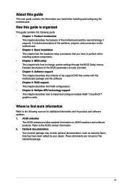
DIMM_A1 DIMM_A2 DIMM_B1 DIMM_B2 1.2.4 System memory The motherboard comes with four Double Data Rate 3 (DDR3) Dual Inline Memory Modules (DIMM) slots. A DDR3 module is notched differently from a DDR or DDR2 module. M5A97 LE R2.0 M5A97 LE R2.0 240-pin DDR3 DIMM sockets Recommended memory configurations Chapter 1 M5A97 LE R2.0 1-9 DO NOT install a DDR or DDR2 memory module to the DDR3 slot.
DIMM_A1 DIMM_A2 DIMM_B1 DIMM_B2 1.2.4 System memory The motherboard comes with four Double Data Rate 3 (DDR3) Dual Inline Memory Modules (DIMM) slots. A DDR3 module is notched differently from a DDR or DDR2 module. M5A97 LE R2.0 M5A97 LE R2.0 240-pin DDR3 DIMM sockets Recommended memory configurations Chapter 1 M5A97 LE R2.0 1-9 DO NOT install a DDR or DDR2 memory module to the DDR3 slot.

M5A97 LE R2.0 User's Manual
Page 24
...from the higher-sized channel is then mapped for single-channel operation. • We recommend that you install 4GB or more on the motherboard. Under the default state, some memory modules for better overclocking capability. • Always install DIMMs with the same CAS latency. To ...system stability, use of memory, we recommend that you want to support a full memory load (4 DIMMs) or overclocking condition. • Visit the ASUS website at a higher frequency, refer to section 3.4 Ai Tweaker menu for the latest QVL. Any excess memory from the blue slots for overclocking may...
...from the higher-sized channel is then mapped for single-channel operation. • We recommend that you install 4GB or more on the motherboard. Under the default state, some memory modules for better overclocking capability. • Always install DIMMs with the same CAS latency. To ...system stability, use of memory, we recommend that you want to support a full memory load (4 DIMMs) or overclocking condition. • Visit the ASUS website at a higher frequency, refer to section 3.4 Ai Tweaker menu for the latest QVL. Any excess memory from the blue slots for overclocking may...
M5A97 LE R2.0 User's Manual
Page 29
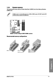
SOCKET AM3+ 1 2 3 M5A97 LE R2.0 4 5 6 Slot No. 1 2 3 4 5 6 Slot Description PCIe 2.0 x16_1 slot [Blue] (at x16 speed) PCIe 2.0 x1_1 slot PCIe 2.0 x1_2 slot PCIe 2.0 x16_2 slot [Black] (at x4 speed) PCI 1 PCI 2 VGA configuration Single VGA/PCIe card Dual VGA/PCIe card PCI Express operating mode PCIe 2.0 x16_1 x16 (Recommend for single VGA) x16 PCIe 2.0 x16_2 x4 x4 M5A97 LE R2.0 1-15 Chapter 1 Failure to do so may cause you physical injury and damage motherboard components. 1.2.5 Expansion slots Unplug the power cord before adding or removing expansion cards.
SOCKET AM3+ 1 2 3 M5A97 LE R2.0 4 5 6 Slot No. 1 2 3 4 5 6 Slot Description PCIe 2.0 x16_1 slot [Blue] (at x16 speed) PCIe 2.0 x1_1 slot PCIe 2.0 x1_2 slot PCIe 2.0 x16_2 slot [Black] (at x4 speed) PCI 1 PCI 2 VGA configuration Single VGA/PCIe card Dual VGA/PCIe card PCI Express operating mode PCIe 2.0 x16_1 x16 (Recommend for single VGA) x16 PCIe 2.0 x16_2 x4 x4 M5A97 LE R2.0 1-15 Chapter 1 Failure to do so may cause you physical injury and damage motherboard components. 1.2.5 Expansion slots Unplug the power cord before adding or removing expansion cards.

M5A97 LE R2.0 User's Manual
Page 30
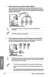
... x16 graphics card to get better performance. • We recommend that you provide sufficient power when running CrossFireX™. • Connect a chassis fan to the motherboard connector labeled CHA_FAN1/2/3 when using multiple graphics cards for this...
... x16 graphics card to get better performance. • We recommend that you provide sufficient power when running CrossFireX™. • Connect a chassis fan to the motherboard connector labeled CHA_FAN1/2/3 when using multiple graphics cards for this...

M5A97 LE R2.0 User's Manual
Page 32
1.2.7 Onboard LEDs Standby Power LED The motherboard comes with a standby power LED that lights up to indicate that you should shut down the system and unplug the power cable before removing or plugging in soft-off mode. The illustration below shows the location of the onboard LED. SB_PWR M5A97 LE R2.0 ON OFF Standby Power Powered Off M5A97 LE R2.0 Onboard LED Chapter 1 1-18 Chapter 1: Product introduction This is a reminder that the system is ON, in sleep mode, or in any motherboard component.
1.2.7 Onboard LEDs Standby Power LED The motherboard comes with a standby power LED that lights up to indicate that you should shut down the system and unplug the power cable before removing or plugging in soft-off mode. The illustration below shows the location of the onboard LED. SB_PWR M5A97 LE R2.0 ON OFF Standby Power Powered Off M5A97 LE R2.0 Onboard LED Chapter 1 1-18 Chapter 1: Product introduction This is a reminder that the system is ON, in sleep mode, or in any motherboard component.

M5A97 LE R2.0 User's Manual
Page 33
... GND RSATA_RXP2 RSATA_RXN2 GND RSATA_TXN2 RSATA_TXP2 GND GND RSATA_TXP3 RSATA_TXN3 GND RSATA_RXN3 RSATA_RXP3 GND GND RSATA_TXP1 RSATA_TXN1 GND RSATA_RXN1 RSATA_RXP1 GND M5A97 LE R2.0 SATA6G_1 SATA6G_3 M5A97 LE R2.0 SATA 6.0Gb/s connectors • These connectors are set the SATA_5-6 connectors to [IDE Mode] to [RAID Mode...Gb/s signal cables for details. • Before creating a RAID set, refer to section 5.1 RAID configurations or the manual bundled in the motherboard support DVD. • When using Serial ATA hard disk drives. If you can create a RAID 0, RAID 1, RAID 5, RAID 10...
... GND RSATA_RXP2 RSATA_RXN2 GND RSATA_TXN2 RSATA_TXP2 GND GND RSATA_TXP3 RSATA_TXN3 GND RSATA_RXN3 RSATA_RXP3 GND GND RSATA_TXP1 RSATA_TXN1 GND RSATA_RXN1 RSATA_RXP1 GND M5A97 LE R2.0 SATA6G_1 SATA6G_3 M5A97 LE R2.0 SATA 6.0Gb/s connectors • These connectors are set the SATA_5-6 connectors to [IDE Mode] to [RAID Mode...Gb/s signal cables for details. • Before creating a RAID set, refer to section 5.1 RAID configurations or the manual bundled in the motherboard support DVD. • When using Serial ATA hard disk drives. If you can create a RAID 0, RAID 1, RAID 5, RAID 10...
M5A97 LE R2.0 User's Manual
Page 34
... the USB module cable to any of maximum 1A (12 W) fan power. • Only the CPU_FAN and CHA_FAN1/2/3 connectors support the ASUS Fan Xpert feature. • If you install two VGA cards, we recommend that you plug the rear chassis fan cable to the USB... GND NC USB+5V USB_P12USB_P12+ GND NC USB+5V USB_P10USB_P10+ GND NC M5A97 LE R2.0 PIN 1 PIN 1 PIN 1 USB+5V USB_P13USB_P13+ GND USB+5V USB_P11USB_P11+ GND USB+5V USB_P9USB_P9+ GND M5A97 LE R2.0 USB2.0 connectors Never connect a 1394 cable to the motherboard connector labeled CHA_FAN1/2 for USB 2.0 ports. 2. USB 2.0 connectors (10-1...
... the USB module cable to any of maximum 1A (12 W) fan power. • Only the CPU_FAN and CHA_FAN1/2/3 connectors support the ASUS Fan Xpert feature. • If you install two VGA cards, we recommend that you plug the rear chassis fan cable to the USB... GND NC USB+5V USB_P12USB_P12+ GND NC USB+5V USB_P10USB_P10+ GND NC M5A97 LE R2.0 PIN 1 PIN 1 PIN 1 USB+5V USB_P13USB_P13+ GND USB+5V USB_P11USB_P11+ GND USB+5V USB_P9USB_P9+ GND M5A97 LE R2.0 USB2.0 connectors Never connect a 1394 cable to the motherboard connector labeled CHA_FAN1/2 for USB 2.0 ports. 2. USB 2.0 connectors (10-1...

M5A97 LE R2.0 User's Manual
Page 35
.... • The front panel audio I/O module is for an additional Sony/Philips Digital Interface (S/PDIF) port. +5V SPDIFOUT GND M5A97 LE R2.0 SPDIF_OUT M5A97 LE R2.0 Digital audio connector Ensure that the audio device of the motherboard high-definition audio capability. • If you want to connect a high definition front panel audio module to this connector, set...
.... • The front panel audio I/O module is for an additional Sony/Philips Digital Interface (S/PDIF) port. +5V SPDIFOUT GND M5A97 LE R2.0 SPDIF_OUT M5A97 LE R2.0 Digital audio connector Ensure that the audio device of the motherboard high-definition audio capability. • If you want to connect a high definition front panel audio module to this connector, set...


