
M5A97 LE R2.0 User's Manual
Page 3
Contents Safety information...vi About this guide...vii M5A97 LE R2.0 specifications summary ix Package contents...xii Installation tools and components xiii Product introduction 1.1 Special features 1-1 1.1.1 Product highlights 1-1 1.1.2 DIP (Dual Intelligent Processors) - TPU (TurboV Processing Unit) & EPU (Energy Processing Unit 1-2 1.1.3 ASUS Exclusive Features 1-2 1.1.4 ASUS Quiet Thermal Solution 1-3 1.1.5 ASUS EZ DIY 1-3 1.1.6 Other special features 1-4 1.2 Motherboard overview 1-5 1.2.1 Before you...
Contents Safety information...vi About this guide...vii M5A97 LE R2.0 specifications summary ix Package contents...xii Installation tools and components xiii Product introduction 1.1 Special features 1-1 1.1.1 Product highlights 1-1 1.1.2 DIP (Dual Intelligent Processors) - TPU (TurboV Processing Unit) & EPU (Energy Processing Unit 1-2 1.1.3 ASUS Exclusive Features 1-2 1.1.4 ASUS Quiet Thermal Solution 1-3 1.1.5 ASUS EZ DIY 1-3 1.1.6 Other special features 1-4 1.2 Motherboard overview 1-5 1.2.1 Before you...
M5A97 LE R2.0 User's Manual
Page 7
...information and for product and software updates. 1. It includes description of the standard package. vii Where to find more information Refer to the ASUS contact information. 2. ASUS websites The ASUS website provides updated information on the motherboard. • Chapter 2: Basic Installation This chapter lists the hardware setup procedures that you need when ...This user guide contains the information you have been added by your dealer. Detailed descriptions of the BIOS parameters are not part of the switches, jumpers, and connectors on ASUS hardware and software products.
...information and for product and software updates. 1. It includes description of the standard package. vii Where to find more information Refer to the ASUS contact information. 2. ASUS websites The ASUS website provides updated information on the motherboard. • Chapter 2: Basic Installation This chapter lists the hardware setup procedures that you need when ...This user guide contains the information you have been added by your dealer. Detailed descriptions of the BIOS parameters are not part of the switches, jumpers, and connectors on ASUS hardware and software products.
M5A97 LE R2.0 User's Manual
Page 11
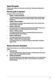
xi M5A97 LE R2.0 specifications summary Back Panel I/O ports Internal I/O connectors / buttons / ...fan connector 3 x Chassis fan connectors (3 x 4-pin) Front panel audio connector 1 x S/PDIF Out header 1 x Clear CMOS jumper 24-pin EATX power connector 4-pin ATX 12V power connector System panel connector 1 x Chassis Intrusion header 1 x COM connector 64Mb Flash... UEFI BIOS, PnP, DMI 2.0, WfM 2.0, SM BIOS 2.7, ACPI 2.0a Multi-language BIOS, ASUS EZ Flash 2, F12 PrintScreen, F3 Shortcut Function and ASUS DRAM SPD (Serieal Presence Detect) memory information WfM 2.0, DMI 2.0, WOL by PME, WOR by...
xi M5A97 LE R2.0 specifications summary Back Panel I/O ports Internal I/O connectors / buttons / ...fan connector 3 x Chassis fan connectors (3 x 4-pin) Front panel audio connector 1 x S/PDIF Out header 1 x Clear CMOS jumper 24-pin EATX power connector 4-pin ATX 12V power connector System panel connector 1 x Chassis Intrusion header 1 x COM connector 64Mb Flash... UEFI BIOS, PnP, DMI 2.0, WfM 2.0, SM BIOS 2.7, ACPI 2.0a Multi-language BIOS, ASUS EZ Flash 2, F12 PrintScreen, F3 Shortcut Function and ASUS DRAM SPD (Serieal Presence Detect) memory information WfM 2.0, DMI 2.0, WOL by PME, WOR by...
M5A97 LE R2.0 User's Manual
Page 21
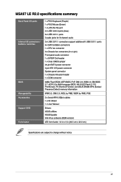
.... Chassis intrusion connector (4-1 pin CHASSIS) 1-23 10. SATA 6.0Gb/s connectors (7-pin SATA6G_1~6) 1-19 6. Digital audio connector (4-1 pin SPDIF_OUT) 1-21 Chapter 1 M5A97 LE R2.0 1-7 ATX power connectors (24-pin EATXPWR, 4-pin ATX12V) 1-22 3. Layout contents Connectors/Jumpers/Slots/LED Page 1. AMD AM3+ CPU socket 1-8 4. CPU and chassis fan connectors (4-pin CPU_FAN and 4-pin CHA_FAN1/2/3) 1-20 2.
.... Chassis intrusion connector (4-1 pin CHASSIS) 1-23 10. SATA 6.0Gb/s connectors (7-pin SATA6G_1~6) 1-19 6. Digital audio connector (4-1 pin SPDIF_OUT) 1-21 Chapter 1 M5A97 LE R2.0 1-7 ATX power connectors (24-pin EATXPWR, 4-pin ATX12V) 1-22 3. Layout contents Connectors/Jumpers/Slots/LED Page 1. AMD AM3+ CPU socket 1-8 4. CPU and chassis fan connectors (4-pin CPU_FAN and 4-pin CHA_FAN1/2/3) 1-20 2.
M5A97 LE R2.0 User's Manual
Page 31
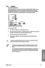
...cap on pins 2-3 for about 5~10 seconds, then move the jumper again to reenter data. Chapter 1 M5A97 LE R2.0 1-17 The onboard button cell battery powers the RAM data in CMOS. Keep the cap on CLRTC jumper default position. After clearing the CMOS, reinstall the battery. •... in CMOS, which include system setup information such as system passwords. M5A97 LE R2.0 CLRTC 12 23 Normal (Default) Clear RTC M5A97 LE R2.0 Clear RTC RAM To erase the RTC RAM: 1. 1.2.6 Jumpers Clear RTC RAM (CLRTC) This jumper allows you to overclocking, use the CPU Parameter Recall (C.P.R) feature. ...
...cap on pins 2-3 for about 5~10 seconds, then move the jumper again to reenter data. Chapter 1 M5A97 LE R2.0 1-17 The onboard button cell battery powers the RAM data in CMOS. Keep the cap on CLRTC jumper default position. After clearing the CMOS, reinstall the battery. •... in CMOS, which include system setup information such as system passwords. M5A97 LE R2.0 CLRTC 12 23 Normal (Default) Clear RTC M5A97 LE R2.0 Clear RTC RAM To erase the RTC RAM: 1. 1.2.6 Jumpers Clear RTC RAM (CLRTC) This jumper allows you to overclocking, use the CPU Parameter Recall (C.P.R) feature. ...
M5A97 LE R2.0 User's Manual
Page 34
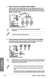
..., then install the module to a slot opening at the back of maximum 1A (12 W) fan power. • Only the CPU_FAN and CHA_FAN1/2/3 connectors support the ASUS Fan Xpert feature. • If you install two VGA cards, we recommend that you plug the rear chassis fan cable to the motherboard connector labeled... connectors are not jumpers! CHA_FAN2 CPU_FAN CHA_FAN3 CHA FAN PWM CHA FAN IN CHA FAN PWR GND CPU FAN PWM CPU FAN IN CPU FAN PWR GND CHA FAN PWM CHA FAN IN CHA FAN PWR GND Chapter 1 M5A97 LE R2.0 CHA_FAN1 GND CHA FAN PWR CHA FAN IN CHA FAN PWM M5A97 LE R2.0 Fan connectors...
..., then install the module to a slot opening at the back of maximum 1A (12 W) fan power. • Only the CPU_FAN and CHA_FAN1/2/3 connectors support the ASUS Fan Xpert feature. • If you install two VGA cards, we recommend that you plug the rear chassis fan cable to the motherboard connector labeled... connectors are not jumpers! CHA_FAN2 CPU_FAN CHA_FAN3 CHA FAN PWM CHA FAN IN CHA FAN PWR GND CPU FAN PWM CPU FAN IN CPU FAN PWR GND CHA FAN PWM CHA FAN IN CHA FAN PWR GND Chapter 1 M5A97 LE R2.0 CHA_FAN1 GND CHA FAN PWR CHA FAN IN CHA FAN PWM M5A97 LE R2.0 Fan connectors...
M5A97 LE R2.0 User's Manual
Page 37
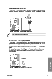
... this connector. Chassis intrusion connector (4-1 pin CHASSIS) This connector is removed or replaced. CHASSIS M5A97 LE R2.0 M5A97 LE R2.0 Chassis intrusion connector M5A97 LE R2.0 1-23 +5VSB_MB Chassis Signal GND Chapter 1 By default, the pin labeled "Chassis Signal" and "Ground" are shorted with a jumper cap. Connect the serial port module cable to this connector, then install the module to...
... this connector. Chassis intrusion connector (4-1 pin CHASSIS) This connector is removed or replaced. CHASSIS M5A97 LE R2.0 M5A97 LE R2.0 Chassis intrusion connector M5A97 LE R2.0 1-23 +5VSB_MB Chassis Signal GND Chapter 1 By default, the pin labeled "Chassis Signal" and "Ground" are shorted with a jumper cap. Connect the serial port module cable to this connector, then install the module to...
M5A97 LE R2.0 User's Manual
Page 54
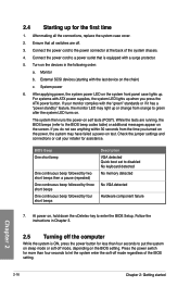
... system case cover. 2. Press the power switch for less than four seconds to green after the system LED turns on test. System power 6. Check the jumper settings and connections or call your monitor complies with ATX power supplies, the system LED lights up when you turned on the power, the system...
... system case cover. 2. Press the power switch for less than four seconds to green after the system LED turns on test. System power 6. Check the jumper settings and connections or call your monitor complies with ATX power supplies, the system LED lights up when you turned on the power, the system...
M5A97 LE R2.0 User's Manual
Page 56
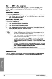
... your motherboard if you in using the first two options. • The BIOS setup screens shown in this section are for information on . See section 1.2.6 Jumpers for reference purposes only, and may not exactly match what you see on your screen. • Ensure that a USB mouse is connected to ensure system...
... your motherboard if you in using the first two options. • The BIOS setup screens shown in this section are for information on . See section 1.2.6 Jumpers for reference purposes only, and may not exactly match what you see on your screen. • Ensure that a USB mouse is connected to ensure system...
M5A97 LE R2.0 User's Manual
Page 60
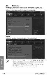
See section 1.2.6 Jumpers for information on how to erase the RTC RAM via the Clear CMOS button. • The Administrator or User Password items on top of the ...
See section 1.2.6 Jumpers for information on how to erase the RTC RAM via the Clear CMOS button. • The Administrator or User Password items on top of the ...

