
User Manual
Page 3
Contents Notices...vi Safety information vii About this guide viii M5A78L-M LX specifications summary ix Chapter 1: Product introduction 1.1 Welcome 1-1 1.2 Package contents 1-1 1.3 Special features 1-1 1.3.1 Product highlights 1-1 1.3.2 Innovative ASUS features 1-3 1.4 Before you proceed 1-5 1.5 Motherboard overview 1-6 1.5.1 Placement direction 1-6 1.5.2 Screw holes 1-6 1.5.3 Motherboard layout 1-7 1.5.4 Layout contents 1-7 1.6 ... 1.8.4 PCI Express x1 slots 1-17 1.8.5 PCI Express x16 slot 1-17 1.9 Jumpers 1-18 1.10 Connectors 1-20 1.10.1 Rear panel ports 1-20 1.10.2 Internal...
Contents Notices...vi Safety information vii About this guide viii M5A78L-M LX specifications summary ix Chapter 1: Product introduction 1.1 Welcome 1-1 1.2 Package contents 1-1 1.3 Special features 1-1 1.3.1 Product highlights 1-1 1.3.2 Innovative ASUS features 1-3 1.4 Before you proceed 1-5 1.5 Motherboard overview 1-6 1.5.1 Placement direction 1-6 1.5.2 Screw holes 1-6 1.5.3 Motherboard layout 1-7 1.5.4 Layout contents 1-7 1.6 ... 1.8.4 PCI Express x1 slots 1-17 1.8.5 PCI Express x16 slot 1-17 1.9 Jumpers 1-18 1.10 Connectors 1-20 1.10.1 Rear panel ports 1-20 1.10.2 Internal...

User Manual
Page 9
...panel) (continued on the next page) ix Integrated ATI Radeon™ HD 3000 GPU Supports max. With ASUS design, this motherboard supports up to DDR3 1866MHz as its standard memory frequency. ** Due to CPU spec., AMD® 100 and 200 series CPUs support up to DDR3 1066MHz. M5A78L-M LX...+ CPU is supported by BIOS version 0401 and later. ** Refer to www.asus.com for the discrete GPUs that support Hybrid CrossFireX™. 1 x PCIe 2.0 x16 slot 2 x PCIe x1 slots 1 x PCI slot 6 x Serial ATA 3Gb/s connectors support RAID 0, RAID 1, RAID 10, and JBOD configurations Realtek Gigabit LAN ALC887...
...panel) (continued on the next page) ix Integrated ATI Radeon™ HD 3000 GPU Supports max. With ASUS design, this motherboard supports up to DDR3 1866MHz as its standard memory frequency. ** Due to CPU spec., AMD® 100 and 200 series CPUs support up to DDR3 1066MHz. M5A78L-M LX...+ CPU is supported by BIOS version 0401 and later. ** Refer to www.asus.com for the discrete GPUs that support Hybrid CrossFireX™. 1 x PCIe 2.0 x16 slot 2 x PCIe x1 slots 1 x PCI slot 6 x Serial ATA 3Gb/s connectors support RAID 0, RAID 1, RAID 10, and JBOD configurations Realtek Gigabit LAN ALC887...

User Manual
Page 10
... connectors 1 x CPU / 1 x Chassis fan connectors 1 x Front panel audio connector 1 x S/PDIF_OUT connector 1 x Speaker connector 1 x System panel connector 1 x 24-pin ATX power connector 1 x 4-pin ATX 12V power connector 16Mb Flash ROM, AMI BIOS, PnP, DMI2.0, WfM2.0, ACPI2.0a, SM BIOS 2.6 ASUS Core unlocker ASUS Q-Fan ASUS CrashFree BIOS3 ASUS EZ Flash2 ASUS AI Charger ASUS MyLogo2 ASUS EPU-4 Engine ASUS Anti Surge Intelligent overclocking tools: - Adjustable DRAM Voltage Overclocking Protection: - M5A78L-M LX...
... connectors 1 x CPU / 1 x Chassis fan connectors 1 x Front panel audio connector 1 x S/PDIF_OUT connector 1 x Speaker connector 1 x System panel connector 1 x 24-pin ATX power connector 1 x 4-pin ATX 12V power connector 16Mb Flash ROM, AMI BIOS, PnP, DMI2.0, WfM2.0, ACPI2.0a, SM BIOS 2.6 ASUS Core unlocker ASUS Q-Fan ASUS CrashFree BIOS3 ASUS EZ Flash2 ASUS AI Charger ASUS MyLogo2 ASUS EPU-4 Engine ASUS Anti Surge Intelligent overclocking tools: - Adjustable DRAM Voltage Overclocking Protection: - M5A78L-M LX...
User Manual
Page 17
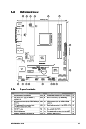
... 3. AMD CPU socket 1-8 12. System panel connector (10-1 pin F_PANEL) 1-24 2. Front panel audio connector (10-1 pin AAFP) 1-21 7. Clear RTC RAM (CLRTC) 1-18 ASUS M5A78L-M LX 1-7 USB device wake-up (3-pin USBPW1-4, USBPW5-10) 1-19 9. ATX power connectors (24-pin EATXPWR, 4-pin 1-22 10. Serial ATA connectors (7-pin SATA1-6) 1-23 14. USB connectors (10-1 pin USB56, USB78, 1-25 ATX12V...
... 3. AMD CPU socket 1-8 12. System panel connector (10-1 pin F_PANEL) 1-24 2. Front panel audio connector (10-1 pin AAFP) 1-21 7. Clear RTC RAM (CLRTC) 1-18 ASUS M5A78L-M LX 1-7 USB device wake-up (3-pin USBPW1-4, USBPW5-10) 1-19 9. ATX power connectors (24-pin EATXPWR, 4-pin 1-22 10. Serial ATA connectors (7-pin SATA1-6) 1-23 14. USB connectors (10-1 pin USB56, USB78, 1-25 ATX12V...

User Manual
Page 30
...25-pin port connects a parallel printer, a scanner, or other audio sources. 5. Line In port (light blue). Port Light Blue (Rear panel) Lime (Rear panel) Pink (Rear panel) Lime (Front panel) Headset 2-channel Line In Line Out Mic In - 4-channel Rear Speaker Out Front Speaker Out Mic In - 6-channel Rear Speaker Out Front ... to support 8-channel audio output. 1-20 Chapter 1: Product introduction This port connects to the audio configuration table below for a PS/2 mouse. 2. 1.10 1.10.1 1 Connectors Rear panel ports 2 3 45 11 10 9 8 7 6 1. Refer to a microphone.
...25-pin port connects a parallel printer, a scanner, or other audio sources. 5. Line In port (light blue). Port Light Blue (Rear panel) Lime (Rear panel) Pink (Rear panel) Lime (Front panel) Headset 2-channel Line In Line Out Mic In - 4-channel Rear Speaker Out Front Speaker Out Mic In - 6-channel Rear Speaker Out Front ... to support 8-channel audio output. 1-20 Chapter 1: Product introduction This port connects to the audio configuration table below for a PS/2 mouse. 2. 1.10 1.10.1 1 Connectors Rear panel ports 2 3 45 11 10 9 8 7 6 1. Refer to a microphone.

User Manual
Page 31
... I /O module cable to [HD Audio]. These two 4-pin Universal Serial Bus (USB) ports connect to USB 2.0 devices. 9. ASUS M5A78L-M LX 1-21 Front panel audio connector (10-1 pin AAFP) This connector is for a VGA monitor or other serial devices. 11. These two 4-pin Universal Serial Bus (USB) ports connect to USB 2.0 devices. 8. Connect one end of ...
... I /O module cable to [HD Audio]. These two 4-pin Universal Serial Bus (USB) ports connect to USB 2.0 devices. 9. ASUS M5A78L-M LX 1-21 Front panel audio connector (10-1 pin AAFP) This connector is for a VGA monitor or other serial devices. 11. These two 4-pin Universal Serial Bus (USB) ports connect to USB 2.0 devices. 8. Connect one end of ...

User Manual
Page 34
... GND IDE_LED+ IDE_LED- F_PANEL PLED PWRBTN PIN 1 M5A78L-M LX +HDLED RESET M5A78L-M LX System panel connector • System power LED (2-pin PLED) This 2-pin connector is for the chassis-mounted system warning speaker. Connect the HDD Activity LED cable to this connector. Connect the chassis power LED cable to this connector. The system power LED lights up or flashes...
... GND IDE_LED+ IDE_LED- F_PANEL PLED PWRBTN PIN 1 M5A78L-M LX +HDLED RESET M5A78L-M LX System panel connector • System power LED (2-pin PLED) This 2-pin connector is for the chassis-mounted system warning speaker. Connect the HDD Activity LED cable to this connector. Connect the chassis power LED cable to this connector. The system power LED lights up or flashes...

User Manual
Page 35
... an additional Sony/Philips Digital Interface (S/PDIF) port. +5V SPDIFOUT GND M5A78L-M LX SPDIF_OUT M5A78L-M LX Digital audio connector Ensure that supports up to a slot opening at the back of these connectors, then install the module to 480Mbps connection speed. The USB 2.0 module is purchased separately. ASUS M5A78L-M LX 1-25 The S/PDIF module is purchased separately. 7. Connect the USB...
... an additional Sony/Philips Digital Interface (S/PDIF) port. +5V SPDIFOUT GND M5A78L-M LX SPDIF_OUT M5A78L-M LX Digital audio connector Ensure that supports up to a slot opening at the back of these connectors, then install the module to 480Mbps connection speed. The USB 2.0 module is purchased separately. ASUS M5A78L-M LX 1-25 The S/PDIF module is purchased separately. 7. Connect the USB...


