User Manual
Page 21
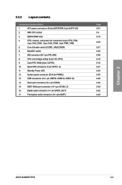
... connectors (7-pin SATA1-5) 11. USB connectors (10-1 pin USB78, USB910, USB1112) 14. IEEE 1394a port connector (10-1 pin IE1394_2) 16. DDR3 DIMM slots 4. Clear RTC RAM (3-pin CLRTC) 10. Standby Power LED 12. Serial port connector (10-1 pin COM1) 15. Digital audio connector (4-1 pin SPDIF_OUT) 17. switch 7. CPU overvoltage setting (3-pin...) 8. Front panel audio connector (10-1 pin AAFP) Page 2-31 2-5 2-10 2-30 2-21 2-20 2-26 2-19 2-18 2-27 2-35 2-33 2-28 2-29 2-29 2-32 2-32 Chapter 2 ASUS M4N98TD EVO 2-3
... connectors (7-pin SATA1-5) 11. USB connectors (10-1 pin USB78, USB910, USB1112) 14. IEEE 1394a port connector (10-1 pin IE1394_2) 16. DDR3 DIMM slots 4. Clear RTC RAM (3-pin CLRTC) 10. Standby Power LED 12. Serial port connector (10-1 pin COM1) 15. Digital audio connector (4-1 pin SPDIF_OUT) 17. switch 7. CPU overvoltage setting (3-pin...) 8. Front panel audio connector (10-1 pin AAFP) Page 2-31 2-5 2-10 2-30 2-21 2-20 2-26 2-19 2-18 2-27 2-35 2-33 2-28 2-29 2-29 2-32 2-32 Chapter 2 ASUS M4N98TD EVO 2-3
User Manual
Page 36
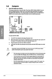
..., reinstall the battery. • You do not help, remove the onboard battery and move the cap back to clear the Real Time Clock (RTC) RAM in CMOS, which include system setup information such as system passwords. For system failure due to overclocking. Move the jumper cap from pins 1-2 (default) ... jumper again to enable C.P.R. You must turn ON the computer. 4. Plug the power cord and turn off is required to clear the CMOS RTC RAM data. You can automatically reset parameter settings to default values. • Due to the chipset behavior, AC power off and on the power supply ...
..., reinstall the battery. • You do not help, remove the onboard battery and move the cap back to clear the Real Time Clock (RTC) RAM in CMOS, which include system setup information such as system passwords. For system failure due to overclocking. Move the jumper cap from pins 1-2 (default) ... jumper again to enable C.P.R. You must turn ON the computer. 4. Plug the power cord and turn off is required to clear the CMOS RTC RAM data. You can automatically reset parameter settings to default values. • Due to the chipset behavior, AC power off and on the power supply ...
User Manual
Page 78
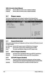
... (POS) only] Sets the ACPI suspend mode to S1/POS (Power On Suspend). [S3 only] Sets the ACPI suspend mode to S3/STR (Suspend To RAM). [Auto] The system automatically configures the ACPI suspend mode. 3.7.2 [Disabled] [Enabled] ACPI 2.0 Support [Enabled] The system will not add additional tables as per ACPI 2.0 specifications...
... (POS) only] Sets the ACPI suspend mode to S1/POS (Power On Suspend). [S3 only] Sets the ACPI suspend mode to S3/STR (Suspend To RAM). [Auto] The system automatically configures the ACPI suspend mode. 3.7.2 [Disabled] [Enabled] ACPI 2.0 Support [Enabled] The system will not add additional tables as per ACPI 2.0 specifications...

User Manual
Page 84
... 3: BIOS setup 3.8.3 Security The Security menu items allow you to set a supervisor password, the other security settings. again to erase the RTC RAM. To set your BIOS password, you have set or change the system security settings. See section 2.6 Jumpers for information on top of at least...Select the Change Supervisor Password item and press . 2. After you can clear clear it by erasing the CMOS Real Time Clock (RTC) RAM. Select an item then press to display the configuration options. After you set a password, this item to change other items appear to ...
... 3: BIOS setup 3.8.3 Security The Security menu items allow you to set a supervisor password, the other security settings. again to erase the RTC RAM. To set your BIOS password, you have set or change the system security settings. See section 2.6 Jumpers for information on top of at least...Select the Change Supervisor Password item and press . 2. After you can clear clear it by erasing the CMOS Real Time Clock (RTC) RAM. Select an item then press to display the configuration options. After you set a password, this item to change other items appear to ...
User Manual
Page 89
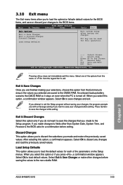
... for each of the options from this menu or from the Exit menu to ensure the values you selected are saved to the CMOS RAM. Select Ok to discard any changes and load the previously saved values. When you select this menu. An onboard backup battery sustains the CMOS... a message asking if you want to save your changes before saving the values to the non-volatile RAM. Pressing does not immediately exit this option or if you press , a confirmation window appears. Chapter 3 ASUS M4N98TD EVO 3-33 F10 key can be used for the BIOS items, and save the changes while exiting. Exit...
... for each of the options from this menu or from the Exit menu to ensure the values you selected are saved to the CMOS RAM. Select Ok to discard any changes and load the previously saved values. When you select this menu. An onboard backup battery sustains the CMOS... a message asking if you want to save your changes before saving the values to the non-volatile RAM. Pressing does not immediately exit this option or if you press , a confirmation window appears. Chapter 3 ASUS M4N98TD EVO 3-33 F10 key can be used for the BIOS items, and save the changes while exiting. Exit...


