User Manual
Page 4
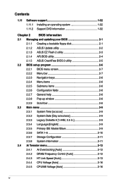
Contents 1.11 Software support 1-32 1.11.1 Installing an operating system 1-32 1.11.2 Support DVD information 1-32 Chapter 2 BIOS information 2.1 Managing and updating your BIOS 2-1 2.1.1 Creating a bootable floppy disk 2-1 2.1.2 ASUS Update utility 2-2 2.1.3 ASUS EZ Flash 2 utility 2-3 2.1.4 AFUDOS utility 2-4 2.1.5 ASUS CrashFree BIOS 2 utility 2-5 2.2 BIOS setup program 2-6 2.2.1 BIOS menu screen 2-7 2.2.2 Menu bar 2-7 2.2.3 Navigation keys 2-8 2.2.4 Menu items 2-8 2.2.5 Submenu items 2-8 2.2.6 Configuration...
Contents 1.11 Software support 1-32 1.11.1 Installing an operating system 1-32 1.11.2 Support DVD information 1-32 Chapter 2 BIOS information 2.1 Managing and updating your BIOS 2-1 2.1.1 Creating a bootable floppy disk 2-1 2.1.2 ASUS Update utility 2-2 2.1.3 ASUS EZ Flash 2 utility 2-3 2.1.4 AFUDOS utility 2-4 2.1.5 ASUS CrashFree BIOS 2 utility 2-5 2.2 BIOS setup program 2-6 2.2.1 BIOS menu screen 2-7 2.2.2 Menu bar 2-7 2.2.3 Navigation keys 2-8 2.2.4 Menu items 2-8 2.2.5 Submenu items 2-8 2.2.6 Configuration...

User Manual
Page 37
5. If you install SATA hard disk drives to the SATA connectors, you intend to create a Serial ATA RAID set the SATA Mode select item in the bundled support DVD before using these connectors, set using Serial ATA hard disk drives. • SATA1-4 connectors are for the Serial ATA signal cables ...ATA 3Gb/s hard disk and optical disk drives. The data transfer rate of SATA ports to RAID mode, all SATA ports run at RAID mode together. • You must install Windows XP® Service Pack 1 or later version before connecting devices to the manual bundled in the motherboard support DVD. &#...
5. If you install SATA hard disk drives to the SATA connectors, you intend to create a Serial ATA RAID set the SATA Mode select item in the bundled support DVD before using these connectors, set using Serial ATA hard disk drives. • SATA1-4 connectors are for the Serial ATA signal cables ...ATA 3Gb/s hard disk and optical disk drives. The data transfer rate of SATA ports to RAID mode, all SATA ports run at RAID mode together. • You must install Windows XP® Service Pack 1 or later version before connecting devices to the manual bundled in the motherboard support DVD. &#...

User Manual
Page 39
...these connectors, then install the module to prevent... connector at the back of the floppy disk drive. • Pin 5 on the connector is purchased separately. Floppy disk drive connector (34-1 pin FLOPPY) This... connector is purchased separately. 8. Chapter 1: Product introduction 1-27 USB connectors (10-1 pin USB78, USB910, USB1112) These connectors are for a Floppy Disk... Drive (FDD) signal cable. The USB 2.0 module is for USB 2.0 ports. These USB connectors comply with a covered Pin 5. • The Floppy Disk Drive...
...these connectors, then install the module to prevent... connector at the back of the floppy disk drive. • Pin 5 on the connector is purchased separately. Floppy disk drive connector (34-1 pin FLOPPY) This... connector is purchased separately. 8. Chapter 1: Product introduction 1-27 USB connectors (10-1 pin USB78, USB910, USB1112) These connectors are for a Floppy Disk... Drive (FDD) signal cable. The USB 2.0 module is for USB 2.0 ports. These USB connectors comply with a covered Pin 5. • The Floppy Disk Drive...
User Manual
Page 68
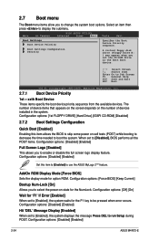
... ~ xxth Boot Device These items specify the boot device priority sequence from the available devices. A virtual floppy disk drive (Floppy Drive B: ) may appear when you set to [Disabled], BIOS performs all the POST items....] [Enabled] Set this item allows the BIOS to skip some power on the number of devices installed in the system. Configuration options: [Force BIOS] [Keep Current] Bootup Num-Lock [On] Allows...waits for option ROM. Configuration options: [Disabled] [Enabled] 2-24 ASUS M4N72-E 2.7 Boot menu The Boot menu items allow you to select the power-on state for the NumLock.
... ~ xxth Boot Device These items specify the boot device priority sequence from the available devices. A virtual floppy disk drive (Floppy Drive B: ) may appear when you set to [Disabled], BIOS performs all the POST items....] [Enabled] Set this item allows the BIOS to skip some power on the number of devices installed in the system. Configuration options: [Force BIOS] [Keep Current] Bootup Num-Lock [On] Allows...waits for option ROM. Configuration options: [Disabled] [Enabled] 2-24 ASUS M4N72-E 2.7 Boot menu The Boot menu items allow you to select the power-on state for the NumLock.


