
User Manual
Page 16
... ASUS M4N72-E The illustration below shows the location of the following precautions before you install motherboard components or change any motherboard settings. • Unplug the power cord from the wall socket before removing or plugging in any component, place it on a grounded antistatic pad or in soft-off the ATX ...power supply and detach its power cord. Onboard LED The motherboard comes with a standby power LED that lights up to indicate that the system is a reminder that came...
... ASUS M4N72-E The illustration below shows the location of the following precautions before you install motherboard components or change any motherboard settings. • Unplug the power cord from the wall socket before removing or plugging in any component, place it on a grounded antistatic pad or in soft-off the ATX ...power supply and detach its power cord. Onboard LED The motherboard comes with a standby power LED that lights up to indicate that the system is a reminder that came...

User Manual
Page 18
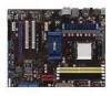
1.5.3 Motherboard layout 1.5.4 Layout contents Connectors/Jumpers/Slots 1. Serial ATA connectors (7-pin SATA1-6) 8. IEEE 1394a connector (10-1 pin IE1394_2) 16. Optical drive audio in connector (4-pin CD) ... (10-1 pin AAFP) Page 1-19 1-23 1-19 1-7 1-22 1-10 1-25 1-24 1-4 1-22 1-18 1-26 1-17 1-27 1-30 1-29 1-27 1-28 1-28 1-29 1-6 ASUS M4N72-E Keyboard/mouse power (3-pin PS2_USBPW56) 2. ATX power connectors (24-pin EATXPWR, 4-pin ATX12V) 3. USB device wake-up (3-pin USBPW1-4, USBPW7-10, USBPW1112) 4. DDR2 DIMM slots 7. Onboard LED (SB_PWR) 10.
1.5.3 Motherboard layout 1.5.4 Layout contents Connectors/Jumpers/Slots 1. Serial ATA connectors (7-pin SATA1-6) 8. IEEE 1394a connector (10-1 pin IE1394_2) 16. Optical drive audio in connector (4-pin CD) ... (10-1 pin AAFP) Page 1-19 1-23 1-19 1-7 1-22 1-10 1-25 1-24 1-4 1-22 1-18 1-26 1-17 1-27 1-30 1-29 1-27 1-28 1-28 1-29 1-6 ASUS M4N72-E Keyboard/mouse power (3-pin PS2_USBPW56) 2. ATX power connectors (24-pin EATXPWR, 4-pin ATX12V) 3. USB device wake-up (3-pin USBPW1-4, USBPW7-10, USBPW1112) 4. DDR2 DIMM slots 7. Onboard LED (SB_PWR) 10.
User Manual
Page 66
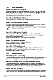
...do not wish to display the detected speed. Configuration options: [Disabled] [Enabled] When a computer is not connected to the motherboard, the field shows N/A. This feature requires an ATX power supply that turns on the +5VSB lead. Configuration options: [Disabled] [Enabled] Power On By RTC Alarm [Disabled] ...Date and RTC Alarm Time appear with an external modem. Select [Ignored] if you do not wish to display the detected voltage output. 2-22 ASUS M4N72-E Configuration options: [Power On] [Power Off] [Last State] Power On By PCI/PCIE Device [Disabled] Allows you to enable or disable...
...do not wish to display the detected speed. Configuration options: [Disabled] [Enabled] When a computer is not connected to the motherboard, the field shows N/A. This feature requires an ATX power supply that turns on the +5VSB lead. Configuration options: [Disabled] [Enabled] Power On By RTC Alarm [Disabled] ...Date and RTC Alarm Time appear with an external modem. Select [Ignored] if you do not wish to display the detected voltage output. 2-22 ASUS M4N72-E Configuration options: [Power On] [Power Off] [Last State] Power On By PCI/PCIE Device [Disabled] Allows you to enable or disable...


