User Manual
Page 25
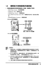
... PIN1)。 3. SPEAKER、RESET 與 PWRSW IDE_LED 與 PLED PIN1 PIN1 4 25 PWR Ground Reset Ground 10-1 pin IDE_LED RESET PWRSW * Requires an ATX power supply. 紅色 1 表示 PIN1 的位置 PLED+ PLEDPWR GND IDELED+ IDELED-
... PIN1)。 3. SPEAKER、RESET 與 PWRSW IDE_LED 與 PLED PIN1 PIN1 4 25 PWR Ground Reset Ground 10-1 pin IDE_LED RESET PWRSW * Requires an ATX power supply. 紅色 1 表示 PIN1 的位置 PLED+ PLEDPWR GND IDELED+ IDELED-
User Manual
Page 26
Asus Q-Connector 華碩 Q-Connector Q-Connector Q-Connector Q-Connector 1.9 24-pin 或 20-pin 24-pin 4-pin 的 ATX+12V 連接 ATX12V 24-pin ATX 20- 2. pin ATX 26
Asus Q-Connector 華碩 Q-Connector Q-Connector Q-Connector Q-Connector 1.9 24-pin 或 20-pin 24-pin 4-pin 的 ATX+12V 連接 ATX12V 24-pin ATX 20- 2. pin ATX 26
User Manual
Page 11
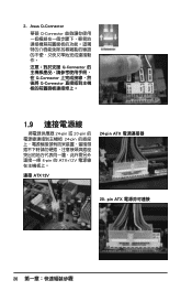
M4N72-E specifications summary Internal I/O connectors BIOS features Support CD contents Form factor 3 x USB connectors support additional 6 USB ports 1 x Floppy disk drive connector 1 x IDE connector 1 x COM connector 6 x ... Power connector 1 x System Panel (Q-Connector) 8 Mb Flash ROM, AMI BIOS, PnP, DMI 2.0, WfM2.0, SM BIOS 2.5, ACPI 2.0, ASUS EZ Flash 2, ASUS CrashFree BIOS 2 Express Gate ASUS PC Probe II ASUS Update Anti-Virus Utility (OEM version) ASUS AI Suite ATX form factor: 12 in x 9.6 in (30.5 cm x 24.4 cm) * Specifications are subject to change without notice. xi
M4N72-E specifications summary Internal I/O connectors BIOS features Support CD contents Form factor 3 x USB connectors support additional 6 USB ports 1 x Floppy disk drive connector 1 x IDE connector 1 x COM connector 6 x ... Power connector 1 x System Panel (Q-Connector) 8 Mb Flash ROM, AMI BIOS, PnP, DMI 2.0, WfM2.0, SM BIOS 2.5, ACPI 2.0, ASUS EZ Flash 2, ASUS CrashFree BIOS 2 Express Gate ASUS PC Probe II ASUS Update Anti-Virus Utility (OEM version) ASUS AI Suite ATX form factor: 12 in x 9.6 in (30.5 cm x 24.4 cm) * Specifications are subject to change without notice. xi

User Manual
Page 16
...plugging in any component, switch off mode. This is ON, in sleep mode, or in soft-off the ATX power supply and detach its power cord. Onboard LED The motherboard comes with a standby power LED that lights up to indicate that the system is a reminder that came with...; Hold components by the edges to the motherboard, peripherals, or components. Failure to do so may cause severe damage to avoid touching the ICs on a grounded antistatic pad or in the bag that you install or remove any motherboard component. 1.4 Before you proceed Take note of the onboard LED. 1-4 ASUS M4N72-E
...plugging in any component, switch off mode. This is ON, in sleep mode, or in soft-off the ATX power supply and detach its power cord. Onboard LED The motherboard comes with a standby power LED that lights up to indicate that the system is a reminder that came with...; Hold components by the edges to the motherboard, peripherals, or components. Failure to do so may cause severe damage to avoid touching the ICs on a grounded antistatic pad or in the bag that you install or remove any motherboard component. 1.4 Before you proceed Take note of the onboard LED. 1-4 ASUS M4N72-E

User Manual
Page 18
... 1-27 1-28 1-28 1-29 1-6 ASUS M4N72-E USB device wake-up (3-pin USBPW1-4, USBPW7-10, USBPW1112) 4. CPU, Chassis and Power Fan connectors (4-pin CPU_FAN, 3-pin CHA_FAN1, 3-pin PWR_FAN) 6. Chassis intrusion connector (4-1 pin CHASSIS) 11. ATX power connectors (24-pin EATXPWR, 4-pin ATX12V) 3. USB connectors (10-1 pin USB78, USB910, USB1112) 15. 1.5.3 Motherboard layout 1.5.4 Layout contents Connectors...
... 1-27 1-28 1-28 1-29 1-6 ASUS M4N72-E USB device wake-up (3-pin USBPW1-4, USBPW7-10, USBPW1112) 4. CPU, Chassis and Power Fan connectors (4-pin CPU_FAN, 3-pin CHA_FAN1, 3-pin PWR_FAN) 6. Chassis intrusion connector (4-1 pin CHASSIS) 11. ATX power connectors (24-pin EATXPWR, 4-pin ATX12V) 3. USB connectors (10-1 pin USB78, USB910, USB1112) 15. 1.5.3 Motherboard layout 1.5.4 Layout contents Connectors...
User Manual
Page 31
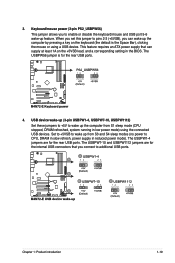
... refresh, power supply in reduced power mode). The USBPW1-4 jumpers are for the internal USB connectors that can wake up feature. 3. This feature requires an ATX power supply that you connect to wake up from S1 sleep mode (CPU stopped, DRAM refreshed, system running in the BIOS. Chapter 1: Product introduction 1-19...
... refresh, power supply in reduced power mode). The USBPW1-4 jumpers are for the internal USB connectors that can wake up feature. 3. This feature requires an ATX power supply that you connect to wake up from S1 sleep mode (CPU stopped, DRAM refreshed, system running in the BIOS. Chapter 1: Product introduction 1-19...

User Manual
Page 35
3. The plugs from the power supply are for an ATX power supply. com/PowerSupplyCalculator/PSCalculator.aspx?SLanguage=en-us for your system, refer to support the motherboard power requirements with more power-consuming devices. Find the proper orientation and push down firmly until the connectors...you are uncertain about the minimum power supply requirement for details. • The ATX 12 V Specification 2.0-compliant (500W) PSU has been tested to the Recommended Power Supply Wattage Calculator at http://support.asus. otherwise, the system will not boot. • Use of 600 W. &#...
3. The plugs from the power supply are for an ATX power supply. com/PowerSupplyCalculator/PSCalculator.aspx?SLanguage=en-us for your system, refer to support the motherboard power requirements with more power-consuming devices. Find the proper orientation and push down firmly until the connectors...you are uncertain about the minimum power supply requirement for details. • The ATX 12 V Specification 2.0-compliant (500W) PSU has been tested to the Recommended Power Supply Wattage Calculator at http://support.asus. otherwise, the system will not boot. • Use of 600 W. &#...
User Manual
Page 38
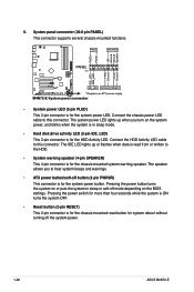
... connector is for the chassis-mounted system warning speaker. Connect the chassis power LED cable to hear system beeps and warnings. • ATX power button/soft-off button (2-pin PWRSR) This connector is for the chassis-mounted reset button for system reboot without turning off mode...cable to the HDD. • System warning speaker (4-pin SPEAKER) This 4-pin connector is in sleep or soft-off the system power. 1-26 ASUS M4N72-E System panel connector (20-8 pin PANEL) This connector supports several chassis-mounted functions. • System power LED (2-pin PLED) This 2-pin connector...
... connector is for the chassis-mounted system warning speaker. Connect the chassis power LED cable to hear system beeps and warnings. • ATX power button/soft-off button (2-pin PWRSR) This connector is for the chassis-mounted reset button for system reboot without turning off mode...cable to the HDD. • System warning speaker (4-pin SPEAKER) This 4-pin connector is in sleep or soft-off the system power. 1-26 ASUS M4N72-E System panel connector (20-8 pin PANEL) This connector supports several chassis-mounted functions. • System power LED (2-pin PLED) This 2-pin connector...
User Manual
Page 66
...Power Key] Power On By PS/2 Mouse [Disabled] Enable or disable PS/2 mouse to the motherboard, the field shows N/A. Select [Ignored] if you do not wish to display the detected voltage output. 2-22 ASUS M4N72-E 2.6.5 APM Configuration Restore on AC Power Loss [Power Off] When set to Power Off, ... On By PS/2 Keyboard [Disabled] Allows you do not wish to turn on the computer in rotations per minute (RPM). This feature requires an ATX power supply that turns on after an AC power loss. Configuration options: [Disabled] [Enabled] 2.6.6 Hardware Monitor CPU/MB Temperature [xxxºC/xxx...
...Power Key] Power On By PS/2 Mouse [Disabled] Enable or disable PS/2 mouse to the motherboard, the field shows N/A. Select [Ignored] if you do not wish to display the detected voltage output. 2-22 ASUS M4N72-E 2.6.5 APM Configuration Restore on AC Power Loss [Power Off] When set to Power Off, ... On By PS/2 Keyboard [Disabled] Allows you do not wish to turn on the computer in rotations per minute (RPM). This feature requires an ATX power supply that turns on after an AC power loss. Configuration options: [Disabled] [Enabled] 2.6.6 Hardware Monitor CPU/MB Temperature [xxxºC/xxx...

