
User Manual
Page 1
M4N68T-M Motherboard
M4N68T-M Motherboard

User Manual
Page 3
Contents Notices...vi Safety information vii About this guide vii M4N68T-M specifications summary ix Chapter: Product introduction 1.1 Welcome 1-1 1.2 Package contents 1-1 1.3 Special features 1-1 1.3.1 Product highlights 1-1 1.3.2 Innovative ASUS features 1-3 1.4 Before you proceed 1-5 1.5 Motherboard overview 1-6 1.5.1 Placement direction 1-6 1.5.2 Screw holes 1-6 1.5.3 Motherboard layout 1-7 1.5.4 Layout contents 1-7 1.6 Central Processing Unit (CPU 1-8 1.6.1 Installing the CPU 1-8 1.6.2 Installing the heatsink and fan 1-10 1.7 System memory...
Contents Notices...vi Safety information vii About this guide vii M4N68T-M specifications summary ix Chapter: Product introduction 1.1 Welcome 1-1 1.2 Package contents 1-1 1.3 Special features 1-1 1.3.1 Product highlights 1-1 1.3.2 Innovative ASUS features 1-3 1.4 Before you proceed 1-5 1.5 Motherboard overview 1-6 1.5.1 Placement direction 1-6 1.5.2 Screw holes 1-6 1.5.3 Motherboard layout 1-7 1.5.4 Layout contents 1-7 1.6 Central Processing Unit (CPU 1-8 1.6.1 Installing the CPU 1-8 1.6.2 Installing the heatsink and fan 1-10 1.7 System memory...

User Manual
Page 6
...Registration, Evaluation, Authorisation, and Restriction of Chemicals) regulatory framework, we published the chemical substances in our products at ASUS REACH website at http://green.asus.com/english/REACH.htm. Operation is no guarantee that the product (electrical and electronic equipment) should not be placed... in municipal waste. REACH Complying with Part 15 of the FCC Rules. DO NOT throw the motherboard in municipal waste....
...Registration, Evaluation, Authorisation, and Restriction of Chemicals) regulatory framework, we published the chemical substances in our products at ASUS REACH website at http://green.asus.com/english/REACH.htm. Operation is no guarantee that the product (electrical and electronic equipment) should not be placed... in municipal waste. REACH Complying with Part 15 of the FCC Rules. DO NOT throw the motherboard in municipal waste....

User Manual
Page 7
... are using the product, ensure that all cables are correctly connected and the power cables are connected. Detailed descriptions of the motherboard and the new technology it , carefully read all the manuals that came with the product, contact a qualified service technician or...BIOS information This chapter tells how to change system settings through the BIOS Setup menus. If you need when installing and configuring the motherboard. Safety information Electrical safety • To prevent electric shock hazard, disconnect the power cable from the electric outlet before relocating the system...
... are using the product, ensure that all cables are correctly connected and the power cables are connected. Detailed descriptions of the motherboard and the new technology it , carefully read all the manuals that came with the product, contact a qualified service technician or...BIOS information This chapter tells how to change system settings through the BIOS Setup menus. If you need when installing and configuring the motherboard. Safety information Electrical safety • To prevent electric shock hazard, disconnect the power cable from the electric outlet before relocating the system...

User Manual
Page 11
... making it , check the items in your package with the list below. 1.2 Package contents Check your motherboard package for buying an ASUS® M4N68T-M motherboard! This motherboard also supports AMD® CPUs in the long line of the above items is damaged or missing, contact ...channel DDR3 memory support and accelerates data transfer rate up to 2000MT/s via HyperTransport™ 1.0-based system bus. ASUS M4N68T-M 1-1 Thank you start installing the motherboard, and hardware devices on it another standout in the new 45nm manufacturing process. Chapter 1 Product introduction 1.1 ...
... making it , check the items in your package with the list below. 1.2 Package contents Check your motherboard package for buying an ASUS® M4N68T-M motherboard! This motherboard also supports AMD® CPUs in the long line of the above items is damaged or missing, contact ...channel DDR3 memory support and accelerates data transfer rate up to 2000MT/s via HyperTransport™ 1.0-based system bus. ASUS M4N68T-M 1-1 Thank you start installing the motherboard, and hardware devices on it another standout in the new 45nm manufacturing process. Chapter 1 Product introduction 1.1 ...

User Manual
Page 12
.../1066 MHz to provide efficient power management for high-speed data retrieval and save. Dual-Channel DDR3 1800 (O.C.) support This motherboard supports DDR3 memory that simultaneously sends different audio streams to your PC! It is a highly integrated Gb LAN controller. It...specification, delivering enhanced scalability and doubling the bus bandwidth for advanced operating systems. Serial ATA 3Gb/s technology and RAID support This motherboard supports hard drives based on your partners on the headphone while playing multi-channel network games. 1-2 Chapter 1: Product introduction ...
.../1066 MHz to provide efficient power management for high-speed data retrieval and save. Dual-Channel DDR3 1800 (O.C.) support This motherboard supports DDR3 memory that simultaneously sends different audio streams to your PC! It is a highly integrated Gb LAN controller. It...specification, delivering enhanced scalability and doubling the bus bandwidth for advanced operating systems. Serial ATA 3Gb/s technology and RAID support This motherboard supports hard drives based on your partners on the headphone while playing multi-channel network games. 1-2 Chapter 1: Product introduction ...

User Manual
Page 13
... system loading to USB drives only. When installing it on USB HDDs or flash drives, connect the drives to the motherboard USB port before entering the OS. ASUS MyLogo2™ Turn your favorite photos into an overclocking button. It supports file downloading to ensure a quiet, cool, and... operation. After the easy setup, Turbo Key boosts performances without interrupting ongoing work or games, simply through pressing the button. 1.3.2 Innovative ASUS features ASUS Express Gate ASUS Express Gate is an auto-recovery tool that contains the BIOS file. ASUS M4N68T-M 1-3
... system loading to USB drives only. When installing it on USB HDDs or flash drives, connect the drives to the motherboard USB port before entering the OS. ASUS MyLogo2™ Turn your favorite photos into an overclocking button. It supports file downloading to ensure a quiet, cool, and... operation. After the easy setup, Turbo Key boosts performances without interrupting ongoing work or games, simply through pressing the button. 1.3.2 Innovative ASUS features ASUS Express Gate ASUS Express Gate is an auto-recovery tool that contains the BIOS file. ASUS M4N68T-M 1-3

User Manual
Page 14
... the CPU default settings when the system hangs due to their default settings. Green ASUS This motherboard and its packaging comply with the ASUS vision of Hazardous Substances (RoHS). ASUS Anti-Surge Protection This special design prevents expensive devices and the motherboard from damage caused by power surges from switching power supply (PSU). eliminates the...
... the CPU default settings when the system hangs due to their default settings. Green ASUS This motherboard and its packaging comply with the ASUS vision of Hazardous Substances (RoHS). ASUS Anti-Surge Protection This special design prevents expensive devices and the motherboard from damage caused by power surges from switching power supply (PSU). eliminates the...

User Manual
Page 15
... you uninstall any component, place it on a grounded antistatic pad or in the bag that you install or remove any motherboard component. Onboard LED The motherboard comes with a standby power LED that lights up to indicate that the system is a reminder that came with the component... supply case, to avoid damaging them due to static electricity. • Hold components by the edges to the motherboard, peripherals, or components. M4N68T-M SB_PWR ON OFF Standby Power Powered Off M4N68T-M Onboard LED ASUS M4N68T-M 1-5 1.4 Before you proceed Take note of the onboard LED.
... you uninstall any component, place it on a grounded antistatic pad or in the bag that you install or remove any motherboard component. Onboard LED The motherboard comes with a standby power LED that lights up to indicate that the system is a reminder that came with the component... supply case, to avoid damaging them due to static electricity. • Hold components by the edges to the motherboard, peripherals, or components. M4N68T-M SB_PWR ON OFF Standby Power Powered Off M4N68T-M Onboard LED ASUS M4N68T-M 1-5 1.4 Before you proceed Take note of the onboard LED.

User Manual
Page 16
The edge with external ports goes to the chassis. DO NOT overtighten the screws! Place this side towards the rear of the chassis as indicated in the correct orientation. 1.5 Motherboard overview 1.5.1 Placement direction When installing the motherboard, ensure that you place it into the chassis in the image below. 1.5.2 Screw holes Place six screws into the holes indicated by circles to secure the motherboard to the rear part of the chassis. Doing so can damage the motherboard. M4N68T-M 1-6 Chapter 1: Product introduction
The edge with external ports goes to the chassis. DO NOT overtighten the screws! Place this side towards the rear of the chassis as indicated in the correct orientation. 1.5 Motherboard overview 1.5.1 Placement direction When installing the motherboard, ensure that you place it into the chassis in the image below. 1.5.2 Screw holes Place six screws into the holes indicated by circles to secure the motherboard to the rear part of the chassis. Doing so can damage the motherboard. M4N68T-M 1-6 Chapter 1: Product introduction

User Manual
Page 17
...ATA connectors (7-pin SATA1-4) 1-24 2. ATX power connectors (24-pin EATXPWR, 4-pin 1-22 11. IDE connector (40-1 pin PRI_IDE) 1-23 15. 1.5.3 Motherboard layout 1 23 4 5 6 20.8cm(8.2in) KB/MS KBPWR ATX12V COM1 DDR3 DIMM_A1 (64bit, 240-pin module) DDR3 DIMM_B1 (64bit, 240-pin module)... Digital audio connector (4-1 pin SPDIF_OUT) 1-27 7. Front panel audio connector (10-1 pin AAFP) 1-21 8. Clear RTC RAM (CLRTC) 1-18 ASUS M4N68T-M 1-7 Keyboard power (3-pin KBPWR) 1-19 9. Onboard LED 1-5 6. CPU and chassis fan connectors (4-pin CPU_FAN and 3-pin CHA_FAN) 1-27 12.
...ATA connectors (7-pin SATA1-4) 1-24 2. ATX power connectors (24-pin EATXPWR, 4-pin 1-22 11. IDE connector (40-1 pin PRI_IDE) 1-23 15. 1.5.3 Motherboard layout 1 23 4 5 6 20.8cm(8.2in) KB/MS KBPWR ATX12V COM1 DDR3 DIMM_A1 (64bit, 240-pin module) DDR3 DIMM_B1 (64bit, 240-pin module)... Digital audio connector (4-1 pin SPDIF_OUT) 1-27 7. Front panel audio connector (10-1 pin AAFP) 1-21 8. Clear RTC RAM (CLRTC) 1-18 ASUS M4N68T-M 1-7 Keyboard power (3-pin KBPWR) 1-19 9. Onboard LED 1-5 6. CPU and chassis fan connectors (4-pin CPU_FAN and 3-pin CHA_FAN) 1-27 12.
User Manual
Page 18
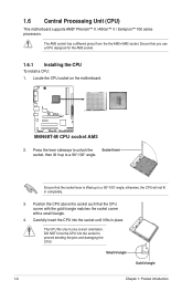
M4N68T-M M4N68T-M CPU socket AM3 2. Position the CPU above the socket such that you use a CPU designed for the AM3 socket. 1.6.1 Installing the CPU To install a CPU: 1. 1.6 Central Processing Unit (CPU) This motherboard supports AMD® Phenom™ II / Athlon™ II / Sempron™ 100 series processors...prevent bending the pins and damaging the CPU! Small triangle Gold triangle 1-8 Chapter 1: Product introduction Locate the CPU socket on the motherboard. Carefully insert the CPU into the socket to a 90°-100° angle; Press the lever sideways to unlock the Socket...
M4N68T-M M4N68T-M CPU socket AM3 2. Position the CPU above the socket such that you use a CPU designed for the AM3 socket. 1.6.1 Installing the CPU To install a CPU: 1. 1.6 Central Processing Unit (CPU) This motherboard supports AMD® Phenom™ II / Athlon™ II / Sempron™ 100 series processors...prevent bending the pins and damaging the CPU! Small triangle Gold triangle 1-8 Chapter 1: Product introduction Locate the CPU socket on the motherboard. Carefully insert the CPU into the socket to a 90°-100° angle; Press the lever sideways to unlock the Socket...

User Manual
Page 19
... motherboard. M4N68T-M CPU_FAN CPU FAN PWM CPU FAN IN CPU FAN PWR GND M4N68T-M CPU fan connector DO NOT forget to the CPU_FAN connector on the side tab to plug this connector. Connect the CPU fan cable to connect the CPU fan connector! Hardware monitoring errors can also refer to secure the CPU. ASUS M4N68T...
... motherboard. M4N68T-M CPU_FAN CPU FAN PWM CPU FAN IN CPU FAN PWR GND M4N68T-M CPU fan connector DO NOT forget to the CPU_FAN connector on the side tab to plug this connector. Connect the CPU fan cable to connect the CPU fan connector! Hardware monitoring errors can also refer to secure the CPU. ASUS M4N68T...

User Manual
Page 20
... the retention mechanism. If the instructions in this section do not have to remove the retention module base when installing the CPU or installing other motherboard components. • If you purchased a separate CPU heatsink and fan assembly, ensure that a Thermal Interface Material is properly applied to the retention module base. 1 2 3 4 ... installed CPU, ensuring that the heatsink fits properly on the retention module base. • The retention module base is already installed on the motherboard upon purchase. • You do not match the CPU documentation, follow the latter. 2.
... the retention mechanism. If the instructions in this section do not have to remove the retention module base when installing the CPU or installing other motherboard components. • If you purchased a separate CPU heatsink and fan assembly, ensure that a Thermal Interface Material is properly applied to the retention module base. 1 2 3 4 ... installed CPU, ensuring that the heatsink fits properly on the retention module base. • The retention module base is already installed on the motherboard upon purchase. • You do not match the CPU documentation, follow the latter. 2.

User Manual
Page 21
...-pin DDR3 DIMM sockets Sockets DIMM_A1 DIMM_B1 ASUS M4N68T-M 1-11 Ensure that the retention bracket is in place. 4. Hardware monitoring errors can occur if you cannot snap the retention bracket in place, connect the CPU fan cable to plug this connector. 1.7 System memory 1.7.1 Overview The motherboard comes with two Double Data Rate 3 (DDR3... to the connector on the retention mechanism to secure the heatsink and fan to the module base. 5. 3. Push down the retention bracket lock on the motherboard labeled CPU_FAN.
...-pin DDR3 DIMM sockets Sockets DIMM_A1 DIMM_B1 ASUS M4N68T-M 1-11 Ensure that the retention bracket is in place. 4. Hardware monitoring errors can occur if you cannot snap the retention bracket in place, connect the CPU fan cable to plug this connector. 1.7 System memory 1.7.1 Overview The motherboard comes with two Double Data Rate 3 (DDR3... to the connector on the retention mechanism to secure the heatsink and fan to the module base. 5. 3. Push down the retention bracket lock on the motherboard labeled CPU_FAN.
User Manual
Page 22
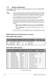
... on 32-bit Windows® OS, when you install 4GB or more memory on the next page 1-12 Chapter 1: Product introduction M4N68T-M Motherboard Qualified Vendors Lists (QVL) DDR3-1800(O.C.)MHz capability Vendor Part No. Apacer 78.0AGCD.CDZ(XMP) 2048MB(Kit of the following: ...24 • DS N/A Heat-Sink Package 8-8-8-24 •• DS N/A Heat-Sink Package 8-8-8-24 •• continued on the motherboard. • This motherboard does not support DIMMs made up of 256 megabits (Mb) chips or less. For optimum compatibility, we recommend that you obtain memory modules...
... on 32-bit Windows® OS, when you install 4GB or more memory on the next page 1-12 Chapter 1: Product introduction M4N68T-M Motherboard Qualified Vendors Lists (QVL) DDR3-1800(O.C.)MHz capability Vendor Part No. Apacer 78.0AGCD.CDZ(XMP) 2048MB(Kit of the following: ...24 • DS N/A Heat-Sink Package 8-8-8-24 •• DS N/A Heat-Sink Package 8-8-8-24 •• continued on the motherboard. • This motherboard does not support DIMMs made up of 256 megabits (Mb) chips or less. For optimum compatibility, we recommend that you obtain memory modules...

User Manual
Page 26
... cause severe damage to unlock the DIMM. 2 Support the DIMM lightly with extra force. 1 DIMM notch 2. Simultaneously press the retaining clips outward to both the motherboard and the components. 1. DO NOT force a DIMM into the socket until the retaining clips snap back in only one direction. Press the retaining clips outward...
... cause severe damage to unlock the DIMM. 2 Support the DIMM lightly with extra force. 1 DIMM notch 2. Simultaneously press the retaining clips outward to both the motherboard and the components. 1. DO NOT force a DIMM into the socket until the retaining clips snap back in only one direction. Press the retaining clips outward...

User Manual
Page 27
...do so may need IRQ assignments. Turn on BIOS setup. 2. ASUS M4N68T-M 1-17 Unplug the power cord before adding or removing expansion cards. 1.8 Expansion slots In the future, you may cause you physical injury and damage motherboard components. 1.8.1 Installing an expansion card To install an expansion card... with the slot and press firmly until the card is already installed in a chassis). 3. Remove the system unit cover (if your motherboard is completely seated on shared slots, ensure that the drivers support "Share IRQ" or that came with the screw you removed earlier....
...do so may need IRQ assignments. Turn on BIOS setup. 2. ASUS M4N68T-M 1-17 Unplug the power cord before adding or removing expansion cards. 1.8 Expansion slots In the future, you may cause you physical injury and damage motherboard components. 1.8.1 Installing an expansion card To install an expansion card... with the slot and press firmly until the card is already installed in a chassis). 3. Remove the system unit cover (if your motherboard is completely seated on shared slots, ensure that the drivers support "Share IRQ" or that came with the screw you removed earlier....

User Manual
Page 31
... M4N68T-M Analog front panel connector • We recommend that supports either High Definition Audio or AC`97 audio standard. Video Graphics Adapter (VGA) port. Front panel audio connector (10-1 pin AAFP) This connector is for pointing devices or other VGA-compatible devices. 10. Connect one end of the motherboard ..., set the Front Panel Select item in the BIOS to this connector. See section 2.4.3 Chipset for a VGA monitor or other serial devices. 11. ASUS M4N68T-M 1-21 PS/2 Keyboard port (purple). This 15-pin port is purchased separately. USB 2.0 ports 1 and 2.
... M4N68T-M Analog front panel connector • We recommend that supports either High Definition Audio or AC`97 audio standard. Video Graphics Adapter (VGA) port. Front panel audio connector (10-1 pin AAFP) This connector is for pointing devices or other VGA-compatible devices. 10. Connect one end of the motherboard ..., set the Front Panel Select item in the BIOS to this connector. See section 2.4.3 Chipset for a VGA monitor or other serial devices. 11. ASUS M4N68T-M 1-21 PS/2 Keyboard port (purple). This 15-pin port is purchased separately. USB 2.0 ports 1 and 2.

User Manual
Page 33
There are three connectors on the Ultra DMA cable connector. M4N68T-M IDE connector ASUS M4N68T-M 1-23 Master Slave Master Slave Cable connector Black Black Gray Black or gray • Pin 20 on the IDE connector is removed to match the ..., and gray. PRI_IDE M4N68T-M PIN1 NOTE:Orient the red markings on the IDE ribbon cable to configure your devices: Single device Two devices Drive jumper setting Cable-Select or Master Cable-Select Master Slave Mode of the following modes to PIN 1. 3. Connect the blue connector to the motherboard's IDE connector, then select...
There are three connectors on the Ultra DMA cable connector. M4N68T-M IDE connector ASUS M4N68T-M 1-23 Master Slave Master Slave Cable connector Black Black Gray Black or gray • Pin 20 on the IDE connector is removed to match the ..., and gray. PRI_IDE M4N68T-M PIN1 NOTE:Orient the red markings on the IDE ribbon cable to configure your devices: Single device Two devices Drive jumper setting Cable-Select or Master Cable-Select Master Slave Mode of the following modes to PIN 1. 3. Connect the blue connector to the motherboard's IDE connector, then select...


