User Manual
Page 4
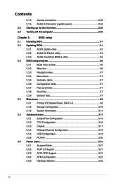
... (system panel 2-34 2.8 Starting up for the first time 2-35 2.9 Turning off the computer 2-35 Chapter 3: BIOS setup 3.1 Knowing BIOS 3-1 3.2 Updating BIOS 3-1 3.2.1 ASUS Update utility 3-2 3.2.2 ASUS EZ Flash 2 utility 3-4 3.2.3 ASUS CrashFree BIOS 3 utility 3-5 3.3 BIOS setup program 3-6 3.3.1 BIOS menu screen 3-6 3.3.2 Menu bar 3-6 3.3.3 Navigation keys 3-7 3.3.4 Menu items 3-7 3.3.5 Submenu items 3-7 3.3.6 Configuration fields 3-7 3.3.7 Pop-up window 3-7 3.3.8 Scroll bar 3-7 3.3.9 General help 3-7 3.4 Main menu 3-8 3.4.1 Primary...
... (system panel 2-34 2.8 Starting up for the first time 2-35 2.9 Turning off the computer 2-35 Chapter 3: BIOS setup 3.1 Knowing BIOS 3-1 3.2 Updating BIOS 3-1 3.2.1 ASUS Update utility 3-2 3.2.2 ASUS EZ Flash 2 utility 3-4 3.2.3 ASUS CrashFree BIOS 3 utility 3-5 3.3 BIOS setup program 3-6 3.3.1 BIOS menu screen 3-6 3.3.2 Menu bar 3-6 3.3.3 Navigation keys 3-7 3.3.4 Menu items 3-7 3.3.5 Submenu items 3-7 3.3.6 Configuration fields 3-7 3.3.7 Pop-up window 3-7 3.3.8 Scroll bar 3-7 3.3.9 General help 3-7 3.4 Main menu 3-8 3.4.1 Primary...

User Manual
Page 5
... Probe II 4-3 4.3.2 Cool 'n' Quiet!™ Technology 4-4 4.3.3 ASUS AI Suite 4-5 4.3.4 ASUS EPU 4-6 4.3.5 ASUS Q-Fan 2 4-7 4.3.6 ASUS TurboV 4-8 4.3.7 ASUS Turbo Key 4-9 4.3.8 ASUS Express Gate 4-10 4.3.9 VIA® High Definition Audio utility 4-11 4.4 RAID configurations 4-12 4.4.1 RAID definitions 4-12 4.4.2 Installing Serial ATA hard disks 4-13 4.4.3 Setting the RAID item in BIOS 4-13 4.4.4 AMD® Option ROM Utility 4-13 4.5 Creating a RAID driver...
... Probe II 4-3 4.3.2 Cool 'n' Quiet!™ Technology 4-4 4.3.3 ASUS AI Suite 4-5 4.3.4 ASUS EPU 4-6 4.3.5 ASUS Q-Fan 2 4-7 4.3.6 ASUS TurboV 4-8 4.3.7 ASUS Turbo Key 4-9 4.3.8 ASUS Express Gate 4-10 4.3.9 VIA® High Definition Audio utility 4-11 4.4 RAID configurations 4-12 4.4.1 RAID definitions 4-12 4.4.2 Installing Serial ATA hard disks 4-13 4.4.3 Setting the RAID item in BIOS 4-13 4.4.4 AMD® Option ROM Utility 4-13 4.5 Creating a RAID driver...

User Manual
Page 9
... added by your dealer. ix Where to find more information Refer to perform when installing system components. ASUS websites The ASUS website provides updated information on the motherboard. • Chapter 3: BIOS setup This chapter tells how to the ASUS contact information. 2. About this guide is organized This guide contains the following sources for additional information...
... added by your dealer. ix Where to find more information Refer to perform when installing system components. ASUS websites The ASUS website provides updated information on the motherboard. • Chapter 3: BIOS setup This chapter tells how to the ASUS contact information. 2. About this guide is organized This guide contains the following sources for additional information...
User Manual
Page 12
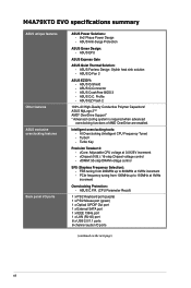
...0125V increment - ASUS CrashFree BIOS 3 - vChipset (N.B.): 16-step Chipset voltage control - ASUS EZ Flash 2 100% All High-Quality Conductive Polymer Capacitors! Intelligent overclocking tools: - ASUS EPU ASUS Express Gate ASUS Quiet Thermal Solution: - ASUS Fanless Design: ...LAN (RJ-45) port 8 x USB 2.0/1.1 ports 8-channel audio I /O ports ASUS Power Solutions: - 8+2 Phase Power Design - ASUS Q-Fan 2 ASUS EZ DIY: - M4A79XTD EVO specifications summary ASUS unique features Other features ASUS exclusive overclocking features Back panel I /O ports (continued on the next page) xii...
...0125V increment - ASUS CrashFree BIOS 3 - vChipset (N.B.): 16-step Chipset voltage control - ASUS EZ Flash 2 100% All High-Quality Conductive Polymer Capacitors! Intelligent overclocking tools: - ASUS EPU ASUS Express Gate ASUS Quiet Thermal Solution: - ASUS Fanless Design: ...LAN (RJ-45) port 8 x USB 2.0/1.1 ports 8-channel audio I /O ports ASUS Power Solutions: - 8+2 Phase Power Design - ASUS Q-Fan 2 ASUS EZ DIY: - M4A79XTD EVO specifications summary ASUS unique features Other features ASUS exclusive overclocking features Back panel I /O ports (continued on the next page) xii...
User Manual
Page 13
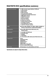
M4A79XTD EVO specifications summary Internal I/O connectors BIOS Manageability Accessories Support DVD Form factor 2 x USB connectors support additional 4 USB ports 1 x COM connector 1 x IDE connector 7 x SATA connectors 1 x Front panel audio connector 1 x ... Chassis fan connectors 1 x Chassis intrusion connector 1 x CD audio-in connector 1 x 24-pin EATX power connector 1 x 4-pin ATX 12V power connector 8Mb Flash ROM, AMI BIOS, PnP, DMI2.0, WfM2.0, SM BIOS 2.3, ACPI2.0a, ASUS EZ Flash 2, ASUS CrashFree BIOS 3 WOL by PME, WOR by PME, WOR by Ring, PXE, Chassis intrusion 1 x Ultra DMA 133/100/66...
M4A79XTD EVO specifications summary Internal I/O connectors BIOS Manageability Accessories Support DVD Form factor 2 x USB connectors support additional 4 USB ports 1 x COM connector 1 x IDE connector 7 x SATA connectors 1 x Front panel audio connector 1 x ... Chassis fan connectors 1 x Chassis intrusion connector 1 x CD audio-in connector 1 x 24-pin EATX power connector 1 x 4-pin ATX 12V power connector 8Mb Flash ROM, AMI BIOS, PnP, DMI2.0, WfM2.0, SM BIOS 2.3, ACPI2.0a, ASUS EZ Flash 2, ASUS CrashFree BIOS 3 WOL by PME, WOR by PME, WOR by Ring, PXE, Chassis intrusion 1 x Ultra DMA 133/100/66...

User Manual
Page 18
... ASUS O.C. The BIOS settings can enhance speech-centric applications like computer fans, air conditioners, and other background noises then eliminates it convenient and easy to conveniently store or load multiple BIOS settings. Not only the beautifully curved fins upgrade the visual enjoyment for motherboard...panel cables to ensure quiet, cool and efficient operation. Q-Fan 2 ASUS Q-Fan 2 technology intelligently adjusts both CPU fan and chassis fan speeds according to system loading to the motherboard. ASUS Q-Shield ASUS Q-Shield's special design makes it in the CMOS or a separate...
... ASUS O.C. The BIOS settings can enhance speech-centric applications like computer fans, air conditioners, and other background noises then eliminates it convenient and easy to conveniently store or load multiple BIOS settings. Not only the beautifully curved fins upgrade the visual enjoyment for motherboard...panel cables to ensure quiet, cool and efficient operation. Q-Fan 2 ASUS Q-Fan 2 technology intelligently adjusts both CPU fan and chassis fan speeds according to system loading to the motherboard. ASUS Q-Shield ASUS Q-Shield's special design makes it in the CMOS or a separate...

User Manual
Page 19
... CPU default settings when the system hangs due to their default settings. Simply shut down and reboot the system, and the BIOS automatically restores the CPU parameters to overclocking failure. C.P.R. ASUS M4A79XTD EVO 1-5 After the easy setup, Turbo Key can boost performances without exiting or rebooting the OS; This easy OC tool allows...
... CPU default settings when the system hangs due to their default settings. Simply shut down and reboot the system, and the BIOS automatically restores the CPU parameters to overclocking failure. C.P.R. ASUS M4A79XTD EVO 1-5 After the easy setup, Turbo Key can boost performances without exiting or rebooting the OS; This easy OC tool allows...
User Manual
Page 32
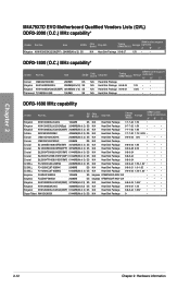
...TX1800KLU-2GK 1024MB SS N/A Heat-Sink Package • • DDR3-1600 MHz capability Vendor Part No. Timing DIMM (BIOS) Voltage DIMM socket support (optional) A* B* C* Corsair CM3X2G1800C8D 2048MB DS N/A Heat-Sink Package • Kingston KHX14400D3K2/...BIOS) Voltage DIMM socket support (optional) A* B* C* N/A Heat-Sink Package 9-9-9-27 1.5V • • DDR3-1800 (O.C.) MHz capability* Vendor Part No. Size SS/ Chip DS Brand Chip NO. Size SS/DS Kingston KHX16000D3K2/2GN(EPP) 2048MB(Kit of 2) SS Chip Brand Chip NO. Chapter 2 M4A79XTD EVO Motherboard...
...TX1800KLU-2GK 1024MB SS N/A Heat-Sink Package • • DDR3-1600 MHz capability Vendor Part No. Timing DIMM (BIOS) Voltage DIMM socket support (optional) A* B* C* Corsair CM3X2G1800C8D 2048MB DS N/A Heat-Sink Package • Kingston KHX14400D3K2/...BIOS) Voltage DIMM socket support (optional) A* B* C* N/A Heat-Sink Package 9-9-9-27 1.5V • • DDR3-1800 (O.C.) MHz capability* Vendor Part No. Size SS/ Chip DS Brand Chip NO. Size SS/DS Kingston KHX16000D3K2/2GN(EPP) 2048MB(Kit of 2) SS Chip Brand Chip NO. Chapter 2 M4A79XTD EVO Motherboard...

User Manual
Page 33
... W1333X2GB8 1024MB SS Transcend TS128MLK64V3U 1024MB SS Transcend TS128MLK72V3U 1024MB SS Transcend TS256MLK64V3U 2048MB DS Chip Brand Chip NO. N/A Heat-Sink Package Timing DIMM Voltage (BIOS) N/A 1.7V DIMM socket support (optional) A* B* C* ••• N/A Heat-Sink Package N/A 1.65V ••• A-Data AD30908C8D-151C E0906 •&#... Heat-Sink Package ••• N/A SEC 813HCH9 K4B1G0846D ••• N/A K4B1G0846D(ECC) ••• N/A SEC816HCH9K4B1G0846D ••• ASUS M4A79XTD EVO 2-13
... W1333X2GB8 1024MB SS Transcend TS128MLK64V3U 1024MB SS Transcend TS128MLK72V3U 1024MB SS Transcend TS256MLK64V3U 2048MB DS Chip Brand Chip NO. N/A Heat-Sink Package Timing DIMM Voltage (BIOS) N/A 1.7V DIMM socket support (optional) A* B* C* ••• N/A Heat-Sink Package N/A 1.65V ••• A-Data AD30908C8D-151C E0906 •&#... Heat-Sink Package ••• N/A SEC 813HCH9 K4B1G0846D ••• N/A K4B1G0846D(ECC) ••• N/A SEC816HCH9K4B1G0846D ••• ASUS M4A79XTD EVO 2-13

User Manual
Page 34
... J5308BASE-AE-E S elpida J1108BABG-DJ-E Micron 8ED22D9JNL Micron 8LD22D9JNL Micron 9HF22D9KPT N/A Heat-Sink Package Samsung SEC 901 HCF8 K4B1G0846E SAMSUNG 846 K4B2G0846BHCF8 Timing Voltage DIMM (BIOS) DIMM socket support (optional) A* B* C* 7 • •• • •• • •• 7 1.5V ± 0.075V • • 7 1.5V • •...2048MB(Kit of dual‑channel memory configuration. • Ensure that you download and update to the latest BIOS at www.asus.com for better cooling performance when using DDR3 2000/1800 MHz.
... J5308BASE-AE-E S elpida J1108BABG-DJ-E Micron 8ED22D9JNL Micron 8LD22D9JNL Micron 9HF22D9KPT N/A Heat-Sink Package Samsung SEC 901 HCF8 K4B1G0846E SAMSUNG 846 K4B2G0846BHCF8 Timing Voltage DIMM (BIOS) DIMM socket support (optional) A* B* C* 7 • •• • •• • •• 7 1.5V ± 0.075V • • 7 1.5V • •...2048MB(Kit of dual‑channel memory configuration. • Ensure that you download and update to the latest BIOS at www.asus.com for better cooling performance when using DDR3 2000/1800 MHz.
User Manual
Page 36
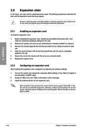
... card. 2. Refer to Chapter 3 for details. 2-16 Chapter 2: Hardware information Remove the system unit cover (if your motherboard is completely seated on BIOS setup. 2. Ensure to the card. Failure to do not need to the chassis with it by adjusting the software settings.... Turn on the next page. 3. Chapter 2 2.5 Expansion slots In the future, you may cause you physical injury and damage motherboard components. 2.5.1 Installing an expansion card To install an expansion card: 1. Replace the system cover. 2.5.2 Configuring an expansion card After installing...
... card. 2. Refer to Chapter 3 for details. 2-16 Chapter 2: Hardware information Remove the system unit cover (if your motherboard is completely seated on BIOS setup. 2. Ensure to the card. Failure to do not need to the chassis with it by adjusting the software settings.... Turn on the next page. 3. Chapter 2 2.5 Expansion slots In the future, you may cause you physical injury and damage motherboard components. 2.5.1 Installing an expansion card To install an expansion card: 1. Replace the system cover. 2.5.2 Configuring an expansion card After installing...

User Manual
Page 39
... 2-3 for about 5-10 seconds, then move the jumper again to re-enter data. For system failure due to pins 2-3. function. ASUS M4A79XTD EVO 2-19 Hold down and reboot the system so the BIOS can clear the CMOS memory of date, time, and system setup parameters by erasing the CMOS RTC RAM data. Move... battery powers the RAM data in CMOS. Keep the cap on CLRTC jumper default position. Shut down the key during the boot process and enter BIOS setup to clear the CMOS RTC RAM data.
... 2-3 for about 5-10 seconds, then move the jumper again to re-enter data. For system failure due to pins 2-3. function. ASUS M4A79XTD EVO 2-19 Hold down and reboot the system so the BIOS can clear the CMOS memory of date, time, and system setup parameters by erasing the CMOS RTC RAM data. Move... battery powers the RAM data in CMOS. Keep the cap on CLRTC jumper default position. Shut down the key during the boot process and enter BIOS setup to clear the CMOS RTC RAM data.

User Manual
Page 40
... setting before you install a new CPU and have not booted for extra-high overvoltage ability, use the BIOS items introduced in BIOS. For system failure due to the wrong setting of this jumper. • Refer to 3.5 Advanced menu for more information about the CPU overvoltage setting. • ...
... setting before you install a new CPU and have not booted for extra-high overvoltage ability, use the BIOS items introduced in BIOS. For system failure due to the wrong setting of this jumper. • Refer to 3.5 Advanced menu for more information about the CPU overvoltage setting. • ...
User Manual
Page 41
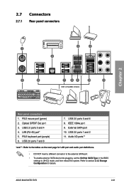
..., set the OnChip SATA Type in the BIOS settings to section 3.4.2 Storage Configuration for details. Refer to [AHCI] mode, and then reboot the system. LAN (RJ-45) port* 5. USB 2.0 ports 7 and 8 7. External SATA port 10. USB 2.0 ports 3 and 4 4. USB 2.0 ports 5 and 6 8. USB 2.0 ports 1 and 2 11. ASUS M4A79XTD EVO 2-21 PS/2 mouse port (green...
..., set the OnChip SATA Type in the BIOS settings to section 3.4.2 Storage Configuration for details. Refer to [AHCI] mode, and then reboot the system. LAN (RJ-45) port* 5. USB 2.0 ports 7 and 8 7. External SATA port 10. USB 2.0 ports 3 and 4 4. USB 2.0 ports 5 and 6 8. USB 2.0 ports 1 and 2 11. ASUS M4A79XTD EVO 2-21 PS/2 mouse port (green...
User Manual
Page 46
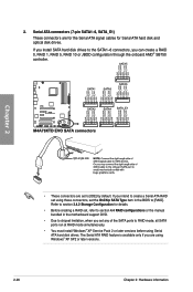
...8226; You must install Windows® XP Service Pack 2 or later versions before using these connectors, set the OnChip SATA Type item in the motherboard support DVD. • Due to chipset limitation, when you intend to create a Serial ATA RAID set to the SATA1-6 connectors, you are ...Refer to section 3.4.2 Storage Configuration for details. • Before creating a RAID set, refer to section 4.4 RAID configurations or the manual bundled in the BIOS to [RAID]. The Serial ATA RAID feature is available only if you can create a RAID 0, RAID 1, RAID 5, RAID 10 or JBOD configuration through...
...8226; You must install Windows® XP Service Pack 2 or later versions before using these connectors, set the OnChip SATA Type item in the motherboard support DVD. • Due to chipset limitation, when you intend to create a Serial ATA RAID set to the SATA1-6 connectors, you are ...Refer to section 3.4.2 Storage Configuration for details. • Before creating a RAID set, refer to section 4.4 RAID configurations or the manual bundled in the BIOS to [RAID]. The Serial ATA RAID feature is available only if you can create a RAID 0, RAID 1, RAID 5, RAID 10 or JBOD configuration through...
User Manual
Page 50
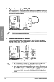
...SPDIF_OUT) This connector is for a chassis-mounted front panel audio I /O module cable to this connector, set the Front Panel Type item in the BIOS setup to this connector. Front panel audio connector (10-1 pin AAFP) This connector is for details. 2-30 Chapter 2: Hardware information Chapter 2 •...-definition front panel audio module to this connector to avail of the system chassis. Refer to a slot opening at the back of the motherboard's high-definition audio capability. • If you want to connect a high-definition front panel audio module to this connector, then install...
...SPDIF_OUT) This connector is for a chassis-mounted front panel audio I /O module cable to this connector, set the Front Panel Type item in the BIOS setup to this connector. Front panel audio connector (10-1 pin AAFP) This connector is for details. 2-30 Chapter 2: Hardware information Chapter 2 •...-definition front panel audio module to this connector to avail of the system chassis. Refer to a slot opening at the back of the motherboard's high-definition audio capability. • If you want to connect a high-definition front panel audio module to this connector, then install...

User Manual
Page 52
... this connector. 10. The system power LED lights up or flashes when data is read from or written to hear system beeps and warnings. • ATX power button/soft-off button (2-pin PWRSW) This connector is for system reboot without turning off mode depending on the system power, and blinks when... to the HDD. • System warning speaker (4-pin SPEAKER) This 4-pin connector is for the HDD Activity LED. The speaker allows you turn on the BIOS settings.
... this connector. 10. The system power LED lights up or flashes when data is read from or written to hear system beeps and warnings. • ATX power button/soft-off button (2-pin PWRSW) This connector is for system reboot without turning off mode depending on the system power, and blinks when... to the HDD. • System warning speaker (4-pin SPEAKER) This 4-pin connector is for the HDD Activity LED. The speaker allows you turn on the BIOS settings.
User Manual
Page 55
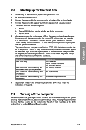
... then runs the power-on . Follow the instructions in the following order: a. Monitor b. ASUS M4A79XTD EVO 2-35 For systems with a surge protector. 5. If you do not see anything within 30 seconds from orange to the BIOS beep codes table below) or additional messages appear on the devices in Chapter 3. 2.9 Turning ... system LED lights up when you turned on the power, the system may light up or change from the time you press the ATX power button. Check the jumper settings and connections or call your monitor complies with the last device on the system front panel case lights...
... then runs the power-on . Follow the instructions in the following order: a. Monitor b. ASUS M4A79XTD EVO 2-35 For systems with a surge protector. 5. If you do not see anything within 30 seconds from orange to the BIOS beep codes table below) or additional messages appear on the devices in Chapter 3. 2.9 Turning ... system LED lights up when you turned on the power, the system may light up or change from the time you press the ATX power button. Check the jumper settings and connections or call your monitor complies with the last device on the system front panel case lights...

User Manual
Page 57
... component that you change the default BIOS settings except in the motherboard CMOS. ASUS CrashFree BIOS 3: Restores the BIOS using a USB flash drive. 3. Save a copy of a trained service personnel. 3.2 Updating BIOS The ASUS website publishes the latest BIOS versions to provide enhancements on these utilities. ASUS M4A79XTD EVO 3-1 ASUS EZ Flash 2: Updates the BIOS using the motherboard support DVD or a USB flash drive...
... component that you change the default BIOS settings except in the motherboard CMOS. ASUS CrashFree BIOS 3: Restores the BIOS using a USB flash drive. 3. Save a copy of a trained service personnel. 3.2 Updating BIOS The ASUS website publishes the latest BIOS versions to provide enhancements on these utilities. ASUS M4A79XTD EVO 3-1 ASUS EZ Flash 2: Updates the BIOS using the motherboard support DVD or a USB flash drive...

User Manual
Page 58
... you to manage, save, and update the motherboard BIOS in the optical drive. 2. Installing ASUS Update To install ASUS Update: 1. To update the BIOS through a network or an Internet Service Provider (ISP). Chapter 3 3-2 Chapter 3: BIOS setup ASUS Update main window appears. 3.2.1 ASUS Update utility The ASUS Update is copied to your system. The ASUS Update utility allows you update the...
... you to manage, save, and update the motherboard BIOS in the optical drive. 2. Installing ASUS Update To install ASUS Update: 1. To update the BIOS through a network or an Internet Service Provider (ISP). Chapter 3 3-2 Chapter 3: BIOS setup ASUS Update main window appears. 3.2.1 ASUS Update utility The ASUS Update is copied to your system. The ASUS Update utility allows you update the...


