User Manual
Page 13
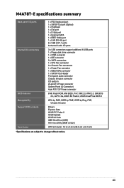
xiii M4A78T-E specifications summary Back panel I/O ports Internal I/O connectors BIOS features Manageability Support DVD contents Form factor 1 x PS/2 keyboard port 1 x S/PDIF Out port (Optical) 1 x HDMI port 1 x DVI ..., AMI BIOS, PnP, DMI 2.0, WfM 2.0, SM BIOS 2.3, ACPI 2.0a, ASUS EZ Flash 2, ASUS CrashFree BIOS 3 WOL by PME, WOR by PME, WOR by Ring, PXE, Chassis Intrusion Drivers Express Gate ASUS PC Probe II ASUS Update ASUS AI Suite AMD OverDrive (AOD) Anti-virus Utility (OEM version) ATX form factor: 12 in x 9.6 in (30.5 cm x 24.4 cm) *Specifications...
xiii M4A78T-E specifications summary Back panel I/O ports Internal I/O connectors BIOS features Manageability Support DVD contents Form factor 1 x PS/2 keyboard port 1 x S/PDIF Out port (Optical) 1 x HDMI port 1 x DVI ..., AMI BIOS, PnP, DMI 2.0, WfM 2.0, SM BIOS 2.3, ACPI 2.0a, ASUS EZ Flash 2, ASUS CrashFree BIOS 3 WOL by PME, WOR by PME, WOR by Ring, PXE, Chassis Intrusion Drivers Express Gate ASUS PC Probe II ASUS Update ASUS AI Suite AMD OverDrive (AOD) Anti-virus Utility (OEM version) ATX form factor: 12 in x 9.6 in (30.5 cm x 24.4 cm) *Specifications...
User Manual
Page 23
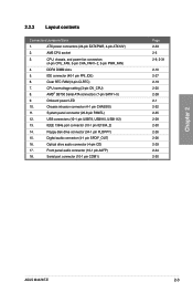
... audio connector (10-1 pin AAFP) 18. CPU overvoltage setting (3-pin OV_CPU) 8. Chassis intrusion connector (4-1 pin CHASSIS) 11. 2.2.2 Layout contents Connectors/Jumpers/Slots 1. Clear RTC RAM (3-pin CLRTC) ...ATX power connectors (24-pin EATXPWR, 4-pin ATX12V) 2. CPU, chassis, and power fan connectors (4-pin CPU_FAN, 3-pin CHA_FAN1-2, 3-pin PWR_FAN) 4. System panel connector (20-8 pin PANEL) 12. Serial port connector (10-1 pin COM1) Page 2-33 2-5 2-9, 2-31 2-10 2-27 2-19 2-20 2-28 2-1 2-32 2-35 2-29 2-30 2-26 2-26 2-29 2-34 2-30 Chapter 2 ASUS M4A78T...
... audio connector (10-1 pin AAFP) 18. CPU overvoltage setting (3-pin OV_CPU) 8. Chassis intrusion connector (4-1 pin CHASSIS) 11. 2.2.2 Layout contents Connectors/Jumpers/Slots 1. Clear RTC RAM (3-pin CLRTC) ...ATX power connectors (24-pin EATXPWR, 4-pin ATX12V) 2. CPU, chassis, and power fan connectors (4-pin CPU_FAN, 3-pin CHA_FAN1-2, 3-pin PWR_FAN) 4. System panel connector (20-8 pin PANEL) 12. Serial port connector (10-1 pin COM1) Page 2-33 2-5 2-9, 2-31 2-10 2-27 2-19 2-20 2-28 2-1 2-32 2-35 2-29 2-30 2-26 2-26 2-29 2-34 2-30 Chapter 2 ASUS M4A78T...

User Manual
Page 52
The signal is for a chassis-mounted intrusion detection sensor or switch. Connect one end of the chassis intrusion sensor or switch cable to this connector when a chassis component is removed or replaced. Chassis intrusion connector (4-1 pin CHASSIS) This connector is then generated as a chassis intrusion event. The chassis intrusion sensor or switch sends a high-level signal to use the chassis intrusion detection feature. Chapter 2 2-32...
The signal is for a chassis-mounted intrusion detection sensor or switch. Connect one end of the chassis intrusion sensor or switch cable to this connector when a chassis component is removed or replaced. Chassis intrusion connector (4-1 pin CHASSIS) This connector is then generated as a chassis intrusion event. The chassis intrusion sensor or switch sends a high-level signal to use the chassis intrusion detection feature. Chapter 2 2-32...

