User Manual
Page 3
Contents Notices...vi Safety information vii About this guide viii M4A785TD-V EVO specifications summary ix Chapter 1: Product introduction 1.1 Welcome 1-1 1.2 Package contents 1-1 1.3 Special features 1-1 1.3.1 Product highlights 1-1 1.3.2 Innovative ASUS features 1-3 1.4 Before you proceed 1-5 1.5 Motherboard overview 1-6 1.5.1 Placement direction 1-6 1.5.2 Screw holes 1-6 1.5.3 Motherboard layout 1-7 1.5.4 Layout contents 1-7 1.6 Central Processing Unit (CPU 1-8 1.6.1 Installing the CPU 1-8 1.6.2 Installing the heatsink and fan 1-10 1.7 System memory 1-11 1.7.1 Overview...
Contents Notices...vi Safety information vii About this guide viii M4A785TD-V EVO specifications summary ix Chapter 1: Product introduction 1.1 Welcome 1-1 1.2 Package contents 1-1 1.3 Special features 1-1 1.3.1 Product highlights 1-1 1.3.2 Innovative ASUS features 1-3 1.4 Before you proceed 1-5 1.5 Motherboard overview 1-6 1.5.1 Placement direction 1-6 1.5.2 Screw holes 1-6 1.5.3 Motherboard layout 1-7 1.5.4 Layout contents 1-7 1.6 Central Processing Unit (CPU 1-8 1.6.1 Installing the CPU 1-8 1.6.2 Installing the heatsink and fan 1-10 1.7 System memory 1-11 1.7.1 Overview...

User Manual
Page 4
Contents 1.11 Software support 1-29 1.11.1 Installing an operating system 1-29 1.11.2 Support DVD information 1-29 Chapter 2: BIOS information 2.1 Managing and updating your BIOS 2-1 2.1.1 ASUS Update utility 2-1 2.1.2 ASUS EZ Flash 2 utility 2-2 2.1.3 ASUS CrashFree BIOS 3 utility 2-3 2.2 BIOS setup program 2-4 2.2.1 BIOS menu screen 2-5 2.2.2 Menu bar 2-5 2.2.3 Navigation keys 2-5 2.2.4 Menu items 2-6 2.2.5 Submenu items 2-6 2.2.6 Configuration fields 2-6 2.2.7 Pop-up window 2-6 2.2.8 Scroll...
Contents 1.11 Software support 1-29 1.11.1 Installing an operating system 1-29 1.11.2 Support DVD information 1-29 Chapter 2: BIOS information 2.1 Managing and updating your BIOS 2-1 2.1.1 ASUS Update utility 2-1 2.1.2 ASUS EZ Flash 2 utility 2-2 2.1.3 ASUS CrashFree BIOS 3 utility 2-3 2.2 BIOS setup program 2-4 2.2.1 BIOS menu screen 2-5 2.2.2 Menu bar 2-5 2.2.3 Navigation keys 2-5 2.2.4 Menu items 2-6 2.2.5 Submenu items 2-6 2.2.6 Configuration fields 2-6 2.2.7 Pop-up window 2-6 2.2.8 Scroll...

User Manual
Page 6
... radio/TV technician for disposal of Chemicals) regulatory framework, we published the chemical substances in our products at ASUS REACH website at http://green.asus.com/english/REACH.htm. Check local regulations for help. This symbol of the crossed out wheeled bin indicates ...equipment does cause harmful interference to which the receiver is no guarantee that may cause undesired operation. DO NOT throw the motherboard in a residential installation. DO NOT throw the mercury-containing button cell battery in the Radio Interference Regulations of the Canadian Department of the ...
... radio/TV technician for disposal of Chemicals) regulatory framework, we published the chemical substances in our products at ASUS REACH website at http://green.asus.com/english/REACH.htm. Check local regulations for help. This symbol of the crossed out wheeled bin indicates ...equipment does cause harmful interference to which the receiver is no guarantee that may cause undesired operation. DO NOT throw the motherboard in a residential installation. DO NOT throw the mercury-containing button cell battery in the Radio Interference Regulations of the Canadian Department of the ...

User Manual
Page 7
... and staples away from connectors, slots, sockets and circuitry. • Avoid dust, humidity, and temperature extremes. Operation safety • Before installing the motherboard and adding devices on a stable surface. • If you are unplugged. • Seek professional assistance before using , contact your local...8226; Never dispose of the electrical outlet you add a device. • Before connecting or removing signal cables from the motherboard, ensure that all power cables are not sure about the voltage of the battery in fire. Safety information Electrical safety •...
... and staples away from connectors, slots, sockets and circuitry. • Avoid dust, humidity, and temperature extremes. Operation safety • Before installing the motherboard and adding devices on a stable surface. • If you are unplugged. • Seek professional assistance before using , contact your local...8226; Never dispose of the electrical outlet you add a device. • Before connecting or removing signal cables from the motherboard, ensure that all power cables are not sure about the voltage of the battery in fire. Safety information Electrical safety •...
User Manual
Page 8
...are linked with a plus sign (+). Example: means that you need when installing and configuring the motherboard. Example: ++ viii DANGER/WARNING: Information to prevent injury to yourself when trying to the ASUS contact information. 2. About this guide is organized This guide contains the following... parts: • Chapter 1: Product introduction This chapter describes the features of the motherboard and the new technology it supports. •...
...are linked with a plus sign (+). Example: means that you need when installing and configuring the motherboard. Example: ++ viii DANGER/WARNING: Information to prevent injury to yourself when trying to the ASUS contact information. 2. About this guide is organized This guide contains the following... parts: • Chapter 1: Product introduction This chapter describes the features of the motherboard and the new technology it supports. •...
User Manual
Page 9
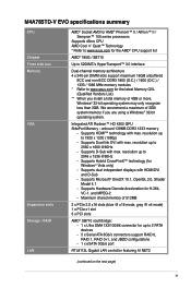
... recognize less than 3GB. onboard 128MB DDR3 1333 memory - We recommend a maximum of 3GB system memory if you install a total memory of 512MB 2 x PCIe 2.0 x16 slots (blue @ x16 mode, gray @ x4 mode) ...page) ix Supports Hybrid CrossFireX™ technology (for H.264, VC-1, and MPEG-2 - M4A785TD-V EVO specifications summary CPU Chipset Front side bus Memory VGA Expansion slots Storage / RAID LAN AMD...8482; 100 series processors Supports 45nm CPU AMD Cool 'n' Quiet™ Technology * Refer to www.asus.com for the AMD® CPU support list AMD® 785G / SB710 Up to 5200MT/s...
... recognize less than 3GB. onboard 128MB DDR3 1333 memory - We recommend a maximum of 3GB system memory if you install a total memory of 512MB 2 x PCIe 2.0 x16 slots (blue @ x16 mode, gray @ x4 mode) ...page) ix Supports Hybrid CrossFireX™ technology (for H.264, VC-1, and MPEG-2 - M4A785TD-V EVO specifications summary CPU Chipset Front side bus Memory VGA Expansion slots Storage / RAID LAN AMD...8482; 100 series processors Supports 45nm CPU AMD Cool 'n' Quiet™ Technology * Refer to www.asus.com for the AMD® CPU support list AMD® 785G / SB710 Up to 5200MT/s...
User Manual
Page 13
... system performance and overclocking capabilities. Before you for the following items. Motherboard Cables Accessories Application DVD Documentation ASUS M4A785TD-V EVO motherboard 4 x Serial ATA cables 1 x Ultra DMA 133/100/66 cable 1 x I/O shield ASUS motherboard Support DVD User Manual If any of ASUS quality motherboards! Thank you start installing the motherboard, and hardware devices on it another standout in the new 45nm manufacturing...
... system performance and overclocking capabilities. Before you for the following items. Motherboard Cables Accessories Application DVD Documentation ASUS M4A785TD-V EVO motherboard 4 x Serial ATA cables 1 x Ultra DMA 133/100/66 cable 1 x I/O shield ASUS motherboard Support DVD User Manual If any of ASUS quality motherboards! Thank you start installing the motherboard, and hardware devices on it another standout in the new 45nm manufacturing...

User Manual
Page 16
...your computer, you quick access to the Internet. ASUS CrashFree BIOS 3 ASUS CrashFree BIOS 3 is an instant-on the system and any faulty cable connections are reported back up to the motherboard USB port before entering the OS. ASUS EZ Flash 2 ASUS EZ Flash 2 allows you turn on environment ...that detects the current system loadings and adjusts the power consumption in real time. When installing it on SATA HDDs, USB HDDs and...
...your computer, you quick access to the Internet. ASUS CrashFree BIOS 3 ASUS CrashFree BIOS 3 is an instant-on the system and any faulty cable connections are reported back up to the motherboard USB port before entering the OS. ASUS EZ Flash 2 ASUS EZ Flash 2 allows you turn on environment ...that detects the current system loadings and adjusts the power consumption in real time. When installing it on SATA HDDs, USB HDDs and...
User Manual
Page 17
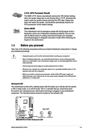
...-off the ATX power supply and detach its packaging comply with the component. • Before you install or remove any motherboard component. This is ON, in sleep mode, or in any component, switch off mode. ASUS M4A785TD-V EVO 1-5 This is in line with the ASUS vision of... the following precautions before you install motherboard components or change any component, place...
...-off the ATX power supply and detach its packaging comply with the component. • Before you install or remove any motherboard component. This is ON, in sleep mode, or in any component, switch off mode. ASUS M4A785TD-V EVO 1-5 This is in line with the ASUS vision of... the following precautions before you install motherboard components or change any component, place...

User Manual
Page 18
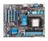
Doing so can damage the motherboard. The edge with external ports goes to the DO NOT overtighten the screws! 1.5 Motherboard overview 1.5.1 Placement direction When installing the motherboard, ensure that you place it into the holes indicated by circles to secure the motherboard to the rear part of the chassis. 1-6 Chapter 1: Product introduction Place this side towards the rear of the chassis as indicated in the image below. 1.5.2 Screw holes Place nine screws into the chassis in the correct orientation.
Doing so can damage the motherboard. The edge with external ports goes to the DO NOT overtighten the screws! 1.5 Motherboard overview 1.5.1 Placement direction When installing the motherboard, ensure that you place it into the holes indicated by circles to secure the motherboard to the rear part of the chassis. 1-6 Chapter 1: Product introduction Place this side towards the rear of the chassis as indicated in the image below. 1.5.2 Screw holes Place nine screws into the chassis in the correct orientation.

User Manual
Page 20
...100° angle; DO NOT force the CPU into the socket until it up to prevent bending the pins and damaging the CPU! 1.6.1 Installing the CPU To install a CPU: 1. DO NOT force the CPU into the socket to a 90°-100° angle. Small triangle Gold triangle 1-8 ...Chapter 1: Product introduction otherwise, the CPU will not fit in place. The CPU fits only in only one correct orientation. 1.6 Central Processing Unit (CPU) This motherboard comes...
...100° angle; DO NOT force the CPU into the socket until it up to prevent bending the pins and damaging the CPU! 1.6.1 Installing the CPU To install a CPU: 1. DO NOT force the CPU into the socket to a 90°-100° angle. Small triangle Gold triangle 1-8 ...Chapter 1: Product introduction otherwise, the CPU will not fit in place. The CPU fits only in only one correct orientation. 1.6 Central Processing Unit (CPU) This motherboard comes...
User Manual
Page 21
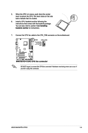
When the CPU is locked. 6. ASUS M4A785TD-V EVO 1-9 Connect the CPU fan cable to the CPU_FAN connector on the side tab to indicate that comes with the heatsink package. The lever clicks on the motherboard. DO NOT forget to plug this connector. Install a CPU heatsink and fan following the instructions that it is in place, push down the socket lever to section 1.6.2 Installing heatsink and fan for instructions. 7. Hardware monitoring errors can also refer to secure the CPU. You can occur if you fail to connect the CPU fan connector! 5.
When the CPU is locked. 6. ASUS M4A785TD-V EVO 1-9 Connect the CPU fan cable to the CPU_FAN connector on the side tab to indicate that comes with the heatsink package. The lever clicks on the motherboard. DO NOT forget to plug this connector. Install a CPU heatsink and fan following the instructions that it is in place, push down the socket lever to section 1.6.2 Installing heatsink and fan for instructions. 7. Hardware monitoring errors can also refer to secure the CPU. You can occur if you fail to connect the CPU fan connector! 5.

User Manual
Page 22
...not have to remove the retention module base when installing the CPU or installing other motherboard components. • If you purchased a separate CPU heatsink and fan assembly, ensure that a Thermal Interface Material is already installed on the motherboard upon purchase. • You do not match ...the CPU documentation, follow the latter. 2. To install the CPU heatsink and fan: 1. Place the heatsink on top of the retention ...
...not have to remove the retention module base when installing the CPU or installing other motherboard components. • If you purchased a separate CPU heatsink and fan assembly, ensure that a Thermal Interface Material is already installed on the motherboard upon purchase. • You do not match ...the CPU documentation, follow the latter. 2. To install the CPU heatsink and fan: 1. Place the heatsink on top of the retention ...

User Manual
Page 23
...the retention bracket in place. 4. Ensure that the retention bracket is in place, connect the CPU fan cable to prevent installation on the motherboard labeled CPU_FAN. When the fan and heatsink assembly is notched differently to the connector on a DDR2 DIMM socket. DDR3 modules...module base. Align the other end of the DDR3 DIMM sockets: Channel Channel A Channel B Sockets DIMM_A1 and DIMM_A2 DIMM_B1 and DIMM_B2 ASUS M4A785TD-V EVO 1-11 The figure illustrates the location of the retention bracket to connect the CPU fan connector! A DDR3 module has the same physical...
...the retention bracket in place. 4. Ensure that the retention bracket is in place, connect the CPU fan cable to prevent installation on the motherboard labeled CPU_FAN. When the fan and heatsink assembly is notched differently to the connector on a DDR2 DIMM socket. DDR3 modules...module base. Align the other end of the DDR3 DIMM sockets: Channel Channel A Channel B Sockets DIMM_A1 and DIMM_A2 DIMM_B1 and DIMM_B2 ASUS M4A785TD-V EVO 1-11 The figure illustrates the location of the retention bracket to connect the CPU fan connector! A DDR3 module has the same physical...

User Manual
Page 24
... non-ECC DDR3 DIMMs into the DIMM sockets. • You may install a maximum of the lower-sized channel for the dual-channel configuration. Any excess memory from the same vendor. • Due to 16GB memory modules on each slot. M4A785TD-V EVO Motherboard Qualified Vendors Lists (QVL) DDR3-1866(O.C.)MHz capability Vendor Part No. For...
... non-ECC DDR3 DIMMs into the DIMM sockets. • You may install a maximum of the lower-sized channel for the dual-channel configuration. Any excess memory from the same vendor. • Due to 16GB memory modules on each slot. M4A785TD-V EVO Motherboard Qualified Vendors Lists (QVL) DDR3-1866(O.C.)MHz capability Vendor Part No. For...

User Manual
Page 28
...the notch on the DIMM matches the break on the socket. 2 DIMM notch 1 1 Unlocked retaining clip A DIMM is properly seated. 1.7.3 Installing a DIMM Unplug the power supply before adding or removing DIMMs or other system components. DIMM notch 1-16 Chapter 1: Product introduction Press the ...retaining clips outward to both the motherboard and the components. 1. The DIMM might get damaged 1 when it fits in place 3 and the DIMM is keyed with your ...
...the notch on the DIMM matches the break on the socket. 2 DIMM notch 1 1 Unlocked retaining clip A DIMM is properly seated. 1.7.3 Installing a DIMM Unplug the power supply before adding or removing DIMMs or other system components. DIMM notch 1-16 Chapter 1: Product introduction Press the ...retaining clips outward to both the motherboard and the components. 1. The DIMM might get damaged 1 when it fits in place 3 and the DIMM is keyed with your ...
User Manual
Page 29
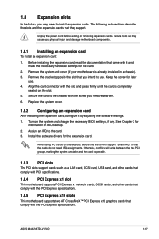
... "Share IRQ" or that they support. ASUS M4A785TD-V EVO 1-17 Turn on the slot. 5. Align the card connector with it by adjusting the software settings. 1. Remove the system unit cover (if your motherboard is completely seated on the system and change the necessary BIOS settings, if any. Install the software drivers for later use . 1.8 Expansion...
... "Share IRQ" or that they support. ASUS M4A785TD-V EVO 1-17 Turn on the slot. 5. Align the card connector with it by adjusting the software settings. 1. Remove the system unit cover (if your motherboard is completely seated on the system and change the necessary BIOS settings, if any. Install the software drivers for later use . 1.8 Expansion...

User Manual
Page 33
...1394a connector (10-1 pin IE1394_1) This connector is for USB 2.0 devices. 1.10.2 Internal connectors 1. Doing so will damage the motherboard! USB 2.0 ports 5 and 6. ASUS M4A785TD-V EVO 1-21 CPU DIMM BIOS setup Suggested list AMD® Phenom™ II x3 720 DDR3 1333 (1GB or higher) Frame Buffer...playback quality, we recommend that you follow the system requirements listed below. Connect the IEEE 1394a module cable to this connector, then install the module to use HDCP compliant devices and software. 17. Never connect a USB cable to the IEEE 1394a connector. Playback of ...
...1394a connector (10-1 pin IE1394_1) This connector is for USB 2.0 devices. 1.10.2 Internal connectors 1. Doing so will damage the motherboard! USB 2.0 ports 5 and 6. ASUS M4A785TD-V EVO 1-21 CPU DIMM BIOS setup Suggested list AMD® Phenom™ II x3 720 DDR3 1333 (1GB or higher) Frame Buffer...playback quality, we recommend that you follow the system requirements listed below. Connect the IEEE 1394a module cable to this connector, then install the module to use HDCP compliant devices and software. 17. Never connect a USB cable to the IEEE 1394a connector. Playback of ...

User Manual
Page 34
...or may not boot up . • We recommend that the 20-pin power plug can provide at http://support.asus. com/PowerSupplyCalculator/PSCalculator.aspx?SLanguage=en-us for an ATX power supply. Find the proper orientation and push down firmly until the connectors completely fit. • We recommend that...the power is inadequate. • DO NOT forget to install additional devices. The system may become unstable or may not boot up if the power is inadequate. • If you intend to fit these connectors in only one orientation. ATX power connectors (24-pin EATXPWR, 4-pin ATX12V) These ...
...or may not boot up . • We recommend that the 20-pin power plug can provide at http://support.asus. com/PowerSupplyCalculator/PSCalculator.aspx?SLanguage=en-us for an ATX power supply. Find the proper orientation and push down firmly until the connectors completely fit. • We recommend that...the power is inadequate. • DO NOT forget to install additional devices. The system may become unstable or may not boot up if the power is inadequate. • If you intend to fit these connectors in only one orientation. ATX power connectors (24-pin EATXPWR, 4-pin ATX12V) These ...

User Manual
Page 36
... See 2.3.4 SATA Configuration for Serial ATA 3Gb/s hard disk and optical disk drives. If you install Serial ATA hard disk drives, you can create a RAID 0, RAID 1, RAID 0+1, or JBOD configuration through the onboard SB710... Manual in the support DVD. 1-24 Chapter 1: Product introduction You could use a USB floppy disk drive when installing Windows® XP operating system on RAID/AHCI, refer to [RAID]. The Serial ATA 3Gb/s is faster than... and SATA6) These connectors are for the Serial ATA signal cables for details. • The motherboard does not provide a floppy disk drive connector.
... See 2.3.4 SATA Configuration for Serial ATA 3Gb/s hard disk and optical disk drives. If you install Serial ATA hard disk drives, you can create a RAID 0, RAID 1, RAID 0+1, or JBOD configuration through the onboard SB710... Manual in the support DVD. 1-24 Chapter 1: Product introduction You could use a USB floppy disk drive when installing Windows® XP operating system on RAID/AHCI, refer to [RAID]. The Serial ATA 3Gb/s is faster than... and SATA6) These connectors are for the Serial ATA signal cables for details. • The motherboard does not provide a floppy disk drive connector.


