
User Manual
Page 1
Motherboard
Motherboard

User Manual
Page 1
M4A78 Motherboard
M4A78 Motherboard

User Manual
Page 3
Contents Notices...vi Safety information vii About this guide vii M4A78 specifications summary ix Chapter 1 Product introduction 1.1 Welcome 1-1 1.2 Package contents 1-1 1.3 Special features 1-1 1.3.1 Product highlights 1-1 1.3.2 Innovative ASUS features 1-3 1.4 Before you proceed 1-5 Onboard LED 1-5 1.5 Motherboard overview 1-6 1.5.1 Placement direction 1-6 1.5.2 Screw holes 1-6 1.5.3 Motherboard layout 1-7 1.5.4 Layout contents 1-7 1.6 Central Processing Unit (CPU 1-8 1.6.1 Installing the CPU 1-8 1.6.2 Installing the heatsink and fan 1-10...
Contents Notices...vi Safety information vii About this guide vii M4A78 specifications summary ix Chapter 1 Product introduction 1.1 Welcome 1-1 1.2 Package contents 1-1 1.3 Special features 1-1 1.3.1 Product highlights 1-1 1.3.2 Innovative ASUS features 1-3 1.4 Before you proceed 1-5 Onboard LED 1-5 1.5 Motherboard overview 1-6 1.5.1 Placement direction 1-6 1.5.2 Screw holes 1-6 1.5.3 Motherboard layout 1-7 1.5.4 Layout contents 1-7 1.6 Central Processing Unit (CPU 1-8 1.6.1 Installing the CPU 1-8 1.6.2 Installing the heatsink and fan 1-10...
User Manual
Page 6
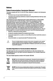
... interference, and • This device must accept any interference received including interference that interference will not occur in a residential installation. vi DO NOT throw the motherboard in municipal waste. However, there is subject to provide reasonable protection against harmful interference in a particular installation. The use of shielded cables for a Class B digital...
... interference, and • This device must accept any interference received including interference that interference will not occur in a residential installation. vi DO NOT throw the motherboard in municipal waste. However, there is subject to provide reasonable protection against harmful interference in a particular installation. The use of shielded cables for a Class B digital...

User Manual
Page 7
... • Place the product on a stable surface. • If you add a device. • Before connecting or removing signal cables from the motherboard, ensure that all power cables are not damaged. These devices could interrupt the grounding circuit. • Ensure that all the manuals that the power cables...ensure that came with the product, contact a qualified service technician or your area. If you need when installing and configuring the motherboard. How this guide This user guide contains the information you are not sure about the voltage of the BIOS parameters are connected.
... • Place the product on a stable surface. • If you add a device. • Before connecting or removing signal cables from the motherboard, ensure that all power cables are not damaged. These devices could interrupt the grounding circuit. • Ensure that all the manuals that the power cables...ensure that came with the product, contact a qualified service technician or your area. If you need when installing and configuring the motherboard. How this guide This user guide contains the information you are not sure about the voltage of the BIOS parameters are connected.
User Manual
Page 11
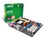
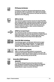
... support and accelerates data transfer rate up to AM3) for buying an ASUS® M4A78 motherboard! Chapter 1: Product introduction 1-1 Thank you start installing the motherboard, and hardware devices on 64-bit architecture. Before you for Phenom X4...motherboard package for the following items. Motherboard Cables Accessories Application DVD Documentations ASUS M4A78 motherboard 1 x Serial ATA cable 1 x Ultra DMA 133/100 cable 1 x I/O shield ASUS motherboard support DVD User manual If any of ASUS quality motherboards! Chapter 1 Product introduction 1.1 Welcome! The motherboard...
... support and accelerates data transfer rate up to AM3) for buying an ASUS® M4A78 motherboard! Chapter 1: Product introduction 1-1 Thank you start installing the motherboard, and hardware devices on 64-bit architecture. Before you for Phenom X4...motherboard package for the following items. Motherboard Cables Accessories Application DVD Documentations ASUS M4A78 motherboard 1 x Serial ATA cable 1 x Ultra DMA 133/100 cable 1 x I/O shield ASUS motherboard support DVD User manual If any of ASUS quality motherboards! Chapter 1 Product introduction 1.1 Welcome! The motherboard...
User Manual
Page 12
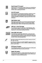
Refer to www.asus.com for advanced operating systems. 1-2 ASUS M4A78 This motherboard provides excellent compatibility and flexibility by default for system stability. The onboard 8-channel HD audio (High Definition Audio, previously codenamed Azalia) CODEC... supported by AM3 / AM2+ CPU only. High Definition Audio Enjoy high-end sound quality on your PC! AMD Cool 'n' Quiet Technology The motherboard supports the AMD Cool 'n' Quiet Technology, which monitors system operation and automatically adjusts CPU voltage and frequency for double speed and bandwidth which enhances ...
Refer to www.asus.com for advanced operating systems. 1-2 ASUS M4A78 This motherboard provides excellent compatibility and flexibility by default for system stability. The onboard 8-channel HD audio (High Definition Audio, previously codenamed Azalia) CODEC... supported by AM3 / AM2+ CPU only. High Definition Audio Enjoy high-end sound quality on your PC! AMD Cool 'n' Quiet Technology The motherboard supports the AMD Cool 'n' Quiet Technology, which monitors system operation and automatically adjusts CPU voltage and frequency for double speed and bandwidth which enhances ...
User Manual
Page 13
..., delivering enhanced scalability and doubling the bus bandwidth for high-speed data retrieval and saves. Serial ATA 3Gb/s technology The motherboard supports next-generation SATA hard drives based on external devices. It automatically provides the most appropriate power usage to analog format and... ASUS EPU The ASUS EPU (Energy Processing Unit) provides total system power management by detecting current PC loadings and intelligently moderating power in applications such as 3D gaming. 1.3.2 SATA on the Go This motherboard supports hard drives based on back I /O provides smart setup and ...
..., delivering enhanced scalability and doubling the bus bandwidth for high-speed data retrieval and saves. Serial ATA 3Gb/s technology The motherboard supports next-generation SATA hard drives based on external devices. It automatically provides the most appropriate power usage to analog format and... ASUS EPU The ASUS EPU (Energy Processing Unit) provides total system power management by detecting current PC loadings and intelligently moderating power in applications such as 3D gaming. 1.3.2 SATA on the Go This motherboard supports hard drives based on back I /O provides smart setup and ...
User Manual
Page 14
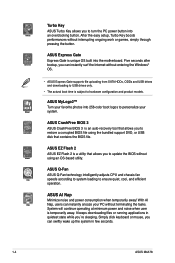
...With AI Nap, users can swiftly wake up the system in few seconds. 1-4 ASUS M4A78 After the easy setup, Turbo Key boosts performances without using the bundled support DVD, or USB disk that contains the BIOS file. ASUS MyLogo2™ Turn your PC without entering the Windows® OS. •...minimum power and noise when user is unique OS built into an overclocking button. ASUS EZ Flash 2 ASUS EZ Flash 2 is an auto-recovery tool that allows you to turn the PC power button into the motherboard. Simply click keyboard or mouse, you ´re sleeping. It keeps downloading ...
...With AI Nap, users can swiftly wake up the system in few seconds. 1-4 ASUS M4A78 After the easy setup, Turbo Key boosts performances without using the bundled support DVD, or USB disk that contains the BIOS file. ASUS MyLogo2™ Turn your PC without entering the Windows® OS. •...minimum power and noise when user is unique OS built into an overclocking button. ASUS EZ Flash 2 ASUS EZ Flash 2 is an auto-recovery tool that allows you to turn the PC power button into the motherboard. Simply click keyboard or mouse, you ´re sleeping. It keeps downloading ...
User Manual
Page 15
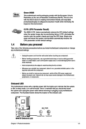
... of the following precautions before you uninstall any component, switch off mode. C.P.R. Simply shut down the system and unplug the power cable before touching any motherboard component. Chapter 1: Product introduction 1-5 Failure to do so may cause severe damage to safeguard consumers' health while minimizing the impact on the use a grounded wrist... on the environment. This is a reminder that lights up to open the system chassis and clear the RTC data. C.P.R. (CPU Parameter Recall) The BIOS C.P.R. Green ASUS This motherboard and its power cord.
... of the following precautions before you uninstall any component, switch off mode. C.P.R. Simply shut down the system and unplug the power cable before touching any motherboard component. Chapter 1: Product introduction 1-5 Failure to do so may cause severe damage to safeguard consumers' health while minimizing the impact on the use a grounded wrist... on the environment. This is a reminder that lights up to open the system chassis and clear the RTC data. C.P.R. (CPU Parameter Recall) The BIOS C.P.R. Green ASUS This motherboard and its power cord.
User Manual
Page 16
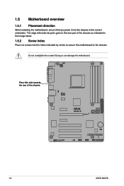
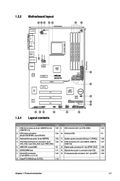
The edge with external ports goes to the rear part of the chassis. 1-6 ASUS M4A78 Do not overtighten the screws! 1.5 Motherboard overview 1.5.1 Placement direction When installing the motherboard, ensure that you place it into the chassis in the image below. 1.5.2 Screw holes Place six screws into the holes indicated by circles to secure the motherboard to the chassis. Place this side towards the rear of the chassis as indicated in the correct orientation. Doing so can damage the motherboard.
The edge with external ports goes to the rear part of the chassis. 1-6 ASUS M4A78 Do not overtighten the screws! 1.5 Motherboard overview 1.5.1 Placement direction When installing the motherboard, ensure that you place it into the chassis in the image below. 1.5.2 Screw holes Place six screws into the holes indicated by circles to secure the motherboard to the chassis. Place this side towards the rear of the chassis as indicated in the correct orientation. Doing so can damage the motherboard.
User Manual
Page 17
...) 2. DDR2 DIMM slots 1-11 14. Serial ATA connectors (7-pin SATA1, 2, 3, 5, 6) 1-25 15. CPU/Chassis/Power fan connectors (4-pin 1-29 12. AMD CPU socket AM2+ 1-8 13. 1.5.3 Motherboard layout 1.5.4 Layout contents Connectors/Jumpers/Slots Page Connectors/Jumpers/Slots 1. Front panel audio connector (10-1 pin AAFP) 8.
...) 2. DDR2 DIMM slots 1-11 14. Serial ATA connectors (7-pin SATA1, 2, 3, 5, 6) 1-25 15. CPU/Chassis/Power fan connectors (4-pin 1-29 12. AMD CPU socket AM2+ 1-8 13. 1.5.3 Motherboard layout 1.5.4 Layout contents Connectors/Jumpers/Slots Page Connectors/Jumpers/Slots 1. Front panel audio connector (10-1 pin AAFP) 8.
User Manual
Page 18
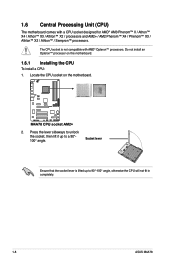
... an Opteron™ processor on the motherboard. 2. Press the lever sideways to unlock the socket, then lift it up to a 90°100° angle. The CPU socket is lifted up to 90°-100° angle, otherwise the CPU will not fit in completely. 1-8 ASUS M4A78 Socket lever Ensure that the socket...; X2 / processors and AM2+ / AM2 Phenom™ X4 / Phenom™ X3 / Athlon™ X2 / Athlon™ / Sempron™ processors. Locate the CPU socket on this motherboard. 1.6.1 Installing the CPU To install a CPU: 1.
... an Opteron™ processor on the motherboard. 2. Press the lever sideways to unlock the socket, then lift it up to a 90°100° angle. The CPU socket is lifted up to 90°-100° angle, otherwise the CPU will not fit in completely. 1-8 ASUS M4A78 Socket lever Ensure that the socket...; X2 / processors and AM2+ / AM2 Phenom™ X4 / Phenom™ X3 / Athlon™ X2 / Athlon™ / Sempron™ processors. Locate the CPU socket on this motherboard. 1.6.1 Installing the CPU To install a CPU: 1.
User Manual
Page 19
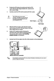
... this connector. Install a CPU heatsink and fan following the instructions that it fits in one correct orientation. Chapter 1: Product introduction 1-9 The lever clicks on the motherboard. Gold triangle 7. Carefully insert the CPU into the socket to indicate that came with a small triangle. 4. When the CPU is locked. 6. Hardware monitoring errors can...
... this connector. Install a CPU heatsink and fan following the instructions that it fits in one correct orientation. Chapter 1: Product introduction 1-9 The lever clicks on the motherboard. Gold triangle 7. Carefully insert the CPU into the socket to indicate that came with a small triangle. 4. When the CPU is locked. 6. Hardware monitoring errors can...
User Manual
Page 20
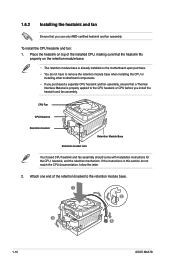
...properly applied to the retention module base. 1 2 3 4 5 1-10 ASUS M4A78 If the instructions in this section do not have to remove the retention module base when installing the CPU or installing other motherboard components. • If you purchased a separate CPU heatsink and fan assembly, ...ensure that a Thermal Interface Material is already installed on the motherboard upon purchase. • You do not match the CPU ...
...properly applied to the retention module base. 1 2 3 4 5 1-10 ASUS M4A78 If the instructions in this section do not have to remove the retention module base when installing the CPU or installing other motherboard components. • If you purchased a separate CPU heatsink and fan assembly, ...ensure that a Thermal Interface Material is already installed on the motherboard upon purchase. • You do not match the CPU ...
User Manual
Page 21
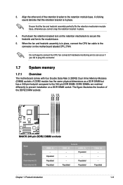
...A clicking sound denotes that the fan and heatsink assembly perfectly fits the retention mechanism module base, otherwise you fail to the connector on the motherboard labeled CPU_FAN. Push down the retention bracket lock on a DDR DIMM socket. A DDR2 module has the same physical dimensions as a DDR ...if you cannot snap the retention bracket in place, connect the CPU fan cable to plug this connector. 1.7 System memory 1.7.1 Overview The motherboard comes with four Double Data Rate 2 (DDR2) Dual Inline Memory Modules (DIMM) sockets. DDR2 DIMMs are notched differently to prevent installation...
...A clicking sound denotes that the fan and heatsink assembly perfectly fits the retention mechanism module base, otherwise you fail to the connector on the motherboard labeled CPU_FAN. Push down the retention bracket lock on a DDR DIMM socket. A DDR2 module has the same physical dimensions as a DDR ...if you cannot snap the retention bracket in place, connect the CPU fan cable to plug this connector. 1.7 System memory 1.7.1 Overview The motherboard comes with four Double Data Rate 2 (DDR2) Dual Inline Memory Modules (DIMM) sockets. DDR2 DIMMs are notched differently to prevent installation...
User Manual
Page 22
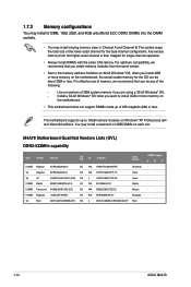
...• Due to the memory address limitation on 32-bit Windows® OS, when you want to 16GB memory modules on the motherboard, the actual usable memory for the OS can be about 3GB or less. For effective use of memory, we recommend that you do... · · · · · · · · · · · · · · · · · · · · · 1-12 ASUS M4A78 You may install varying memory sizes in Channel A and Channel B. The system maps the total size of the lower-sized channel for single-channel operation...
...• Due to the memory address limitation on 32-bit Windows® OS, when you want to 16GB memory modules on the motherboard, the actual usable memory for the OS can be about 3GB or less. For effective use of memory, we recommend that you do... · · · · · · · · · · · · · · · · · · · · · 1-12 ASUS M4A78 You may install varying memory sizes in Channel A and Channel B. The system maps the total size of the lower-sized channel for single-channel operation...
User Manual
Page 27
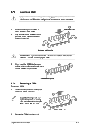
... DIMM socket. 2. Remove the DIMM from the socket. Locked Retaining Clip 1.7.4 Removing a DIMM To remove a DIMM: 1. Simultaneously press the retaining clips outward to both the motherboard and the components. 1. Chapter 1: Product introduction 1 1-17 Align a DIMM on the socket. 2 DDR2 DIMM notch 1 1 Unlocked retaining clip A DDR2 DIMM is properly seated. DO NOT...
... DIMM socket. 2. Remove the DIMM from the socket. Locked Retaining Clip 1.7.4 Removing a DIMM To remove a DIMM: 1. Simultaneously press the retaining clips outward to both the motherboard and the components. 1. Chapter 1: Product introduction 1 1-17 Align a DIMM on the socket. 2 DDR2 DIMM notch 1 1 Unlocked retaining clip A DDR2 DIMM is properly seated. DO NOT...
User Manual
Page 28
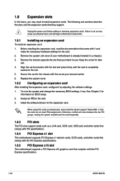
Before installing the expansion card, read the documentation that came with the PCI Express specifications. 1-18 ASUS M4A78 Replace the system cover. 1.8.2 Configuring an expansion card After installing the expansion card, configure it and make the necessary hardware ... firmly until the card is already installed in a chassis). 3. 1.8 Expansion slots In the future, you may cause you physical injury and damage motherboard components. 1.8.1 Installing an expansion card To install an expansion card: 1. Keep the screw for information on shared slots, ensure that the drivers support...
Before installing the expansion card, read the documentation that came with the PCI Express specifications. 1-18 ASUS M4A78 Replace the system cover. 1.8.2 Configuring an expansion card After installing the expansion card, configure it and make the necessary hardware ... firmly until the card is already installed in a chassis). 3. 1.8 Expansion slots In the future, you may cause you physical injury and damage motherboard components. 1.8.1 Installing an expansion card To install an expansion card: 1. Keep the screw for information on shared slots, ensure that the drivers support...
User Manual
Page 34
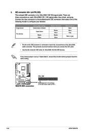
... device Two devices Drive jumper setting Cable-Select or Master Cable-Select Master Slave Mode of device(s) - Connect the blue connector to the motherboard's IDE connector, then select one of the following modes to match the covered hole on the Ultra DMA cable connector. Master Slave Master Slave... black, and gray. If any device jumper is set as "Cable-Select", ensure that all other device jumpers have the same setting. 1-24 ASUS M4A78 There are three connectors on the IDE connector is for Ultra DMA 133/100 IDE devices. This prevents incorrect insertion when you connect the IDE...
... device Two devices Drive jumper setting Cable-Select or Master Cable-Select Master Slave Mode of device(s) - Connect the blue connector to the motherboard's IDE connector, then select one of the following modes to match the covered hole on the Ultra DMA cable connector. Master Slave Master Slave... black, and gray. If any device jumper is set as "Cable-Select", ensure that all other device jumpers have the same setting. 1-24 ASUS M4A78 There are three connectors on the IDE connector is for Ultra DMA 133/100 IDE devices. This prevents incorrect insertion when you connect the IDE...


