User Manual
Page 18
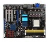
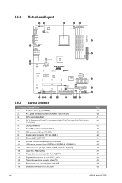
... AAFP) 18. 1.5.3 Motherboard layout 1.5.4 Layout contents Connectors/Jumpers/Slots 1. CPU, Chassis and Power Fan connectors (4-pin CPU_FAN, 3-pin CHA_FAN1, 3-pin PWR_FAN) 5. Clear RTC RAM (CLRTC) 14. Serial port connector (10-1 pin COM1) Page 1-18 1-23 1-7 1-22 1-10 1-25 1-24 1-26 1-4 1-22 1-18 1-27 1-17 1-27 1-28 1-28 1-29 1-29 1-6 ASUS M4A78 PRO CPU socket AM2...
... AAFP) 18. 1.5.3 Motherboard layout 1.5.4 Layout contents Connectors/Jumpers/Slots 1. CPU, Chassis and Power Fan connectors (4-pin CPU_FAN, 3-pin CHA_FAN1, 3-pin PWR_FAN) 5. Clear RTC RAM (CLRTC) 14. Serial port connector (10-1 pin COM1) Page 1-18 1-23 1-7 1-22 1-10 1-25 1-24 1-26 1-4 1-22 1-18 1-27 1-17 1-27 1-28 1-28 1-29 1-29 1-6 ASUS M4A78 PRO CPU socket AM2...

User Manual
Page 50
... recognize these changes and record them in the CMOS RAM of the following procedures: • Restart using the provided utility described in section 2.1 Managing and updating your BIOS. This requires you can cause damage to run this motherboard. 2-6 ASUS M4A78 PRO We recommend to always shut-down procedure. •... and may not exactly match what you see on the motherboard stores the Setup utility. For example, you scroll through the various submenus and make your screen. • Visit the ASUS website at www.asus.com to enter Setup after changing any of the firmware ...
... recognize these changes and record them in the CMOS RAM of the following procedures: • Restart using the provided utility described in section 2.1 Managing and updating your BIOS. This requires you can cause damage to run this motherboard. 2-6 ASUS M4A78 PRO We recommend to always shut-down procedure. •... and may not exactly match what you see on the motherboard stores the Setup utility. For example, you scroll through the various submenus and make your screen. • Visit the ASUS website at www.asus.com to enter Setup after changing any of the firmware ...

