
User Manual
Page 6
... with the limits for radio noise emissions from that the battery should not be placed in our products at ASUS REACH website at http://green.asus.com/english/REACH.htm. REACH Complying with the REACH (Registration, Evaluation, Authorisation, and Restriction of Communications. ...installed and used in municipal waste. If this equipment. These limits are designed to radio communications. vi The use of shielded cables for help. Operation is no guarantee that may cause harmful interference to provide reasonable protection against harmful interference in municipal waste....
... with the limits for radio noise emissions from that the battery should not be placed in our products at ASUS REACH website at http://green.asus.com/english/REACH.htm. REACH Complying with the REACH (Registration, Evaluation, Authorisation, and Restriction of Communications. ...installed and used in municipal waste. If this equipment. These limits are designed to radio communications. vi The use of shielded cables for help. Operation is no guarantee that may cause harmful interference to provide reasonable protection against harmful interference in municipal waste....

User Manual
Page 7
... you are not sure about the voltage of the electrical outlet you encounter technical problems with the package. Before connecting or removing signal cables from the motherboard, ensure that all the manuals that came with the product, contact a qualified service technician or your local power company...installing the motherboard and adding devices on a stable surface. vii When adding or removing devices to fix it , carefully read all power cables are connected. If the power supply is broken, do not try to or from the existing system before using the product, ensure that...
... you are not sure about the voltage of the electrical outlet you encounter technical problems with the package. Before connecting or removing signal cables from the motherboard, ensure that all the manuals that came with the product, contact a qualified service technician or your local power company...installing the motherboard and adding devices on a stable surface. vii When adding or removing devices to fix it , carefully read all power cables are connected. If the power supply is broken, do not try to or from the existing system before using the product, ensure that...

User Manual
Page 11
xi M4A78-EM/1394 specifications summary Internal I/O connectors 3 x USB 2.0 connectors support additional 6 USB 2.0 ports 1 x IDE connector 1 x COM connector 1 x LPT connector 1 x IEEE 1394a connector 5 x SATA connectors 1 x High definition front panel...ATX 12V power connector 8Mb Flash ROM, AMI BIOS, PnP, DMI v2.0, WfM2.0, ACPI v2.0a, SM BIOS 2.5 1 x Serial ATA cable 1 x UltraDMA 133/100/66 cable 1 x I/O shield 1 x User Manual Drivers ASUS PC Probe II ASUS LiveUpdate Utility Anti-Virus software (OEM version) MicroATX form factor: 9.6 in x 9.6 in (24.4 cm x 24.4 cm) BIOS Accessories ...
xi M4A78-EM/1394 specifications summary Internal I/O connectors 3 x USB 2.0 connectors support additional 6 USB 2.0 ports 1 x IDE connector 1 x COM connector 1 x LPT connector 1 x IEEE 1394a connector 5 x SATA connectors 1 x High definition front panel...ATX 12V power connector 8Mb Flash ROM, AMI BIOS, PnP, DMI v2.0, WfM2.0, ACPI v2.0a, SM BIOS 2.5 1 x Serial ATA cable 1 x UltraDMA 133/100/66 cable 1 x I/O shield 1 x User Manual Drivers ASUS PC Probe II ASUS LiveUpdate Utility Anti-Virus software (OEM version) MicroATX form factor: 9.6 in x 9.6 in (24.4 cm x 24.4 cm) BIOS Accessories ...

User Manual
Page 13
... motherboards! This motherboard also supports AMD® CPUs in your package with the list below. 1.2 Package contents ASUS M4A78-EM/1394 motherboard 1 x Serial ATA cable 1 x UltraDMA 133/100/66 cable 1 x I/O shield ASUS motherboard Support DVD User Manual Check your retailer. 1.3 1.3.1 Special features Product highlights AMD® Phenom™ II / Athlon™ x4 / Athlon™ x3 / Athlon™...
... motherboards! This motherboard also supports AMD® CPUs in your package with the list below. 1.2 Package contents ASUS M4A78-EM/1394 motherboard 1 x Serial ATA cable 1 x UltraDMA 133/100/66 cable 1 x I/O shield ASUS motherboard Support DVD User Manual Check your retailer. 1.3 1.3.1 Special features Product highlights AMD® Phenom™ II / Athlon™ x4 / Athlon™ x3 / Athlon™...

User Manual
Page 16
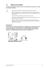
... and reboot the system, and the BIOS automatically restores the CPU parameters to 100 meters at 1 meter accuracy. ASUS AI NET2 ASUS AI NET2 remotely detects the cable connection immediately after turning on the use of creating environment-friendly and recyclable products/packaging to restore a corrupted BIOS ...the BIOS without interrupting ongoing work or games-with the European Union's Restriction on the system, and any faulty cable connections are reported back up to their default settings. 1-4 Chapter 1: Product introduction ASUS EZ Flash 2 ASUS EZ Flash 2 is in real time.
... and reboot the system, and the BIOS automatically restores the CPU parameters to 100 meters at 1 meter accuracy. ASUS AI NET2 ASUS AI NET2 remotely detects the cable connection immediately after turning on the use of creating environment-friendly and recyclable products/packaging to restore a corrupted BIOS ...the BIOS without interrupting ongoing work or games-with the European Union's Restriction on the system, and any faulty cable connections are reported back up to their default settings. 1-4 Chapter 1: Product introduction ASUS EZ Flash 2 ASUS EZ Flash 2 is in real time.
User Manual
Page 17
... wall socket before removing or plugging in soft-off the ATX power supply and detach its power cord. ASUS M4A78-EM/1394 1-5 This is a reminder that you should shut down the system and unplug the power cable before touching any component. • Before handling components, use a grounded wrist strap or touch a safely grounded object or...
... wall socket before removing or plugging in soft-off the ATX power supply and detach its power cord. ASUS M4A78-EM/1394 1-5 This is a reminder that you should shut down the system and unplug the power cable before touching any component. • Before handling components, use a grounded wrist strap or touch a safely grounded object or...

User Manual
Page 21
The lever clicks on the motherboard. 7. Install a CPU heatsink and fan following the instructions that it is in place, push down the socket lever to secure the CPU. When the CPU is locked. You can occur if you fail to section 1.6.2 Installing heatsink and fan for instructions. DO NOT forget to indicate that comes with the heatsink package. Hardware monitoring errors can also refer to plug this connector. 5. 6. ASUS M4A78-EM/1394 1-9 Connect the CPU fan cable to the CPU_FAN connector on the side tab to connect the CPU fan connector!
The lever clicks on the motherboard. 7. Install a CPU heatsink and fan following the instructions that it is in place, push down the socket lever to secure the CPU. When the CPU is locked. You can occur if you fail to section 1.6.2 Installing heatsink and fan for instructions. DO NOT forget to indicate that comes with the heatsink package. Hardware monitoring errors can also refer to plug this connector. 5. 6. ASUS M4A78-EM/1394 1-9 Connect the CPU fan cable to the CPU_FAN connector on the side tab to connect the CPU fan connector!

User Manual
Page 23
..., otherwise you fail to the module base. Hardware monitoring errors can occur if you cannot snap the retention bracket in place, connect the CPU fan cable to the connector on the retention mechanism to secure the heatsink and fan to plug this connector. 1.7 1.7.1 System memory Overview The motherboard comes with four... forget to the retention module base. Align the other end of the DDR2 DIMM sockets: Channel Channel A Channel B Sockets DIMM_A1 and DIMM_A2 DIMM_B1 and DIMM_B2 ASUS M4A78-EM/1394 1-11
..., otherwise you fail to the module base. Hardware monitoring errors can occur if you cannot snap the retention bracket in place, connect the CPU fan cable to the connector on the retention mechanism to secure the heatsink and fan to plug this connector. 1.7 1.7.1 System memory Overview The motherboard comes with four... forget to the retention module base. Align the other end of the DDR2 DIMM sockets: Channel Channel A Channel B Sockets DIMM_A1 and DIMM_A2 DIMM_B1 and DIMM_B2 ASUS M4A78-EM/1394 1-11

User Manual
Page 31
... BLINKING Data activity ORANGE GREEN 100Mbps connection LAN port 6. 7. 8. 9. This port connects to an external audio output device via an optical S/PDIF cable. Rear Speaker Out port (black). Line Out port (lime). This port connects to a headphone or a speaker. LAN (RJ-45) port.... In port (light blue). This port connects to the rear speakers in the 8-channel audio configuration. 10. Side Speaker Out port (gray). ASUS M4A78-EM/1394 1-19 Video Graphics Adapter (VGA) port. This port allows Gigabit connection to the side speakers in the 4, 6, and 8-channel audio configurations...
... BLINKING Data activity ORANGE GREEN 100Mbps connection LAN port 6. 7. 8. 9. This port connects to an external audio output device via an optical S/PDIF cable. Rear Speaker Out port (black). Line Out port (lime). This port connects to a headphone or a speaker. LAN (RJ-45) port.... In port (light blue). This port connects to the rear speakers in the 8-channel audio configuration. 10. Side Speaker Out port (gray). ASUS M4A78-EM/1394 1-19 Video Graphics Adapter (VGA) port. This port allows Gigabit connection to the side speakers in the 4, 6, and 8-channel audio configurations...
User Manual
Page 34
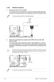
...port connector (10-1 pin COM1) 2. Only the CPU fan supports the ASUS Q-Fan feature. 1-22 Chapter 1: Product introduction DO NOT place jumper caps on the motherboard, ensuring that the black wire of each cable matches the ground pin of the system chassis. The serial port bracket (COM1... flow inside the system may damage the motherboard components. Connect the serial port module cable to the connector, then install the module to the fan connectors. DO NOT forget to connect the fan cables to a slot opening at +12V. Internal connectors The connector is purchased separately. ...
...port connector (10-1 pin COM1) 2. Only the CPU fan supports the ASUS Q-Fan feature. 1-22 Chapter 1: Product introduction DO NOT place jumper caps on the motherboard, ensuring that the black wire of each cable matches the ground pin of the system chassis. The serial port bracket (COM1... flow inside the system may damage the motherboard components. Connect the serial port module cable to the connector, then install the module to the fan connectors. DO NOT forget to connect the fan cables to a slot opening at +12V. Internal connectors The connector is purchased separately. ...

User Manual
Page 36
... connector, then select one of the following modes to configure your devices: Drive jumper setting Single device Cable-Select or Master Cable-Select Two devices Master Slave Mode of device(s) Master Slave Master Slave Cable connector Black Black Gray Black or gray IDE connector (40-1 pin PRI_IDE) • Pin 20 on... the IDE connector is removed to match the covered hole on each Ultra DMA 133/100/66 signal cable: blue, black, and gray. 5. If any device jumper is for Ultra DMA 133/100/66 IDE devices. This prevents incorrect insertion when you ...
... connector, then select one of the following modes to configure your devices: Drive jumper setting Single device Cable-Select or Master Cable-Select Two devices Master Slave Mode of device(s) Master Slave Master Slave Cable connector Black Black Gray Black or gray IDE connector (40-1 pin PRI_IDE) • Pin 20 on... the IDE connector is removed to match the covered hole on each Ultra DMA 133/100/66 signal cable: blue, black, and gray. 5. If any device jumper is for Ultra DMA 133/100/66 IDE devices. This prevents incorrect insertion when you ...

User Manual
Page 37
The Serial ATA 3Gb/s is backward compatible with 133 MB/s (Ultra DMA133). ASUS M4A78-EM/1394 1-25 Connect the IEEE 1394a module cable to this connector, then install the module to the RAID manual in the Support DVD. • If you can create a RAID 0, RAID 1, and RAID 0+1 ... to a slot opening at the back of the Serial ATA 3Gb/s is for an IEEE 1394a port. These connectors are for the Serial ATA signal cables for details. 7. The data transfer rate of the system chassis. See 2.3.4 SATA Configuration for Serial ATA 3Gb/s hard disk and optical disk drives. If...
The Serial ATA 3Gb/s is backward compatible with 133 MB/s (Ultra DMA133). ASUS M4A78-EM/1394 1-25 Connect the IEEE 1394a module cable to this connector, then install the module to the RAID manual in the Support DVD. • If you can create a RAID 0, RAID 1, and RAID 0+1 ... to a slot opening at the back of the Serial ATA 3Gb/s is for an IEEE 1394a port. These connectors are for the Serial ATA signal cables for details. 7. The data transfer rate of the system chassis. See 2.3.4 SATA Configuration for Serial ATA 3Gb/s hard disk and optical disk drives. If...

User Manual
Page 38
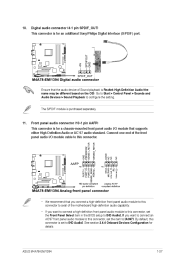
USB connectors (10-1 pin USB78, USB910, USB1112) Never connect a 1394 cable to receive stereo audio input from sound sources such as a CD-ROM, TV tuner, or MPEG card. Optical drive audio connector (4-pin CD) 1-26 Chapter 1: ... 2.0 specification that supports up to a slot opening at the back of these connectors, then install the module to 480Mbps connection speed. Connect the USB module cable to any of the system chassis. The USB 2.0 module is purchased separately. 9. Doing so will damage the motherboard! 8. These connectors are for USB 2.0 ports...
USB connectors (10-1 pin USB78, USB910, USB1112) Never connect a 1394 cable to receive stereo audio input from sound sources such as a CD-ROM, TV tuner, or MPEG card. Optical drive audio connector (4-pin CD) 1-26 Chapter 1: ... 2.0 specification that supports up to a slot opening at the back of these connectors, then install the module to 480Mbps connection speed. Connect the USB module cable to any of the system chassis. The USB 2.0 module is purchased separately. 9. Doing so will damage the motherboard! 8. These connectors are for USB 2.0 ports...
User Manual
Page 39
ASUS M4A78-EM/1394 1-27 10. This connector is Realtek High Definition Audio (the name may be different based on the OS). Ensure that the audio device of Sound playback is for a chassis-mounted front panel audio I /O module cable to this connector, set the Front Panel Select item in the BIOS setup to [HD Audio]. Connect...
ASUS M4A78-EM/1394 1-27 10. This connector is Realtek High Definition Audio (the name may be different based on the OS). Ensure that the audio device of Sound playback is for a chassis-mounted front panel audio I /O module cable to this connector, set the Front Panel Select item in the BIOS setup to [HD Audio]. Connect...

User Manual
Page 40
...-off the system power. • 1-28 Chapter 1: Product introduction Pressing the power switch for the chassis-mounted system warning speaker. Connect the chassis power LED cable to hear system beeps and warnings. The IDE LED lights up when you to this connector. 12. Connect the HDD Activity LED... cable to the HDD. System warning speaker (4-pin SPEAKER) This 4-pin connector is for more than four seconds while the system is in SLEEP or SOFT-...
...-off the system power. • 1-28 Chapter 1: Product introduction Pressing the power switch for the chassis-mounted system warning speaker. Connect the chassis power LED cable to hear system beeps and warnings. The IDE LED lights up when you to this connector. 12. Connect the HDD Activity LED... cable to the HDD. System warning speaker (4-pin SPEAKER) This 4-pin connector is for more than four seconds while the system is in SLEEP or SOFT-...
User Manual
Page 45
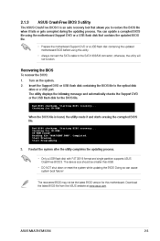
...for this utility. • Always connect the SATA cable to the SATA1/2/3/5/6 connector; Restart the system after the utility completes the updating process. • Only a USB flash disk with FAT 32/16 format and single partition supports ASUS CrashFree BIOS 3. The device size should be the... the updating process. Bad BIOS checksum. You can cause system boot failure! Completed. Download the latest BIOS file from the ASUS website at www.asus.com. ASUS M4A78-EM/1394 2-3 Insert the Support DVD or USB flash disk containing the BIOS file to the optical disk drive or a USB port....
...for this utility. • Always connect the SATA cable to the SATA1/2/3/5/6 connector; Restart the system after the utility completes the updating process. • Only a USB flash disk with FAT 32/16 format and single partition supports ASUS CrashFree BIOS 3. The device size should be the... the updating process. Bad BIOS checksum. You can cause system boot failure! Completed. Download the latest BIOS file from the ASUS website at www.asus.com. ASUS M4A78-EM/1394 2-3 Insert the Support DVD or USB flash disk containing the BIOS file to the optical disk drive or a USB port....

User Manual
Page 61
... run again when you enter the Express Gate environment after clearing its settings. 2.7.3 Check Realtek LAN cable [Disabled] AI NET 2 Enables or disables checking of Express Gate for special functions. Configuration options: [Disabled] [Enabled] ASUS M4A78-EM/1394 2-19 User data includes the Express Gate's settings as well as any personal information stored by the...
... run again when you enter the Express Gate environment after clearing its settings. 2.7.3 Check Realtek LAN cable [Disabled] AI NET 2 Enables or disables checking of Express Gate for special functions. Configuration options: [Disabled] [Enabled] ASUS M4A78-EM/1394 2-19 User data includes the Express Gate's settings as well as any personal information stored by the...


