
User Manual
Page 10
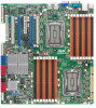
KGPE-D16 specifications summary Processor Support / System Bus 2 x socket G34 (LGA 1944) 8/12 Core AMD® Opteron™ 6000 Series HyperTransport™ Technology 3.0, Core Logic 6.4 GT/s per link (triple link) Northbridge: AMD® SR5690 Southbridge: AMD® SP5100 Form Factor SSI EEB, 12" x 13" ASUS ... DDR3 800/1066/1333 RDIMM Memory Size 1GB, 2GB, 4GB, 8GB, 16GB (RDIMM) 1GB, 2GB, 4GB (UDIMM) Expansion Slots Total PCI/PCI-X/ 6 (follow SSI PCI-E Slots Loacation #) Slot Loacation 1 1 x PCI 32bit/33 MHz Slot Loacation 2 1 x PCI-E x16 (Gen2 x8 Link) Slot Loacation 3 1 x...
KGPE-D16 specifications summary Processor Support / System Bus 2 x socket G34 (LGA 1944) 8/12 Core AMD® Opteron™ 6000 Series HyperTransport™ Technology 3.0, Core Logic 6.4 GT/s per link (triple link) Northbridge: AMD® SR5690 Southbridge: AMD® SP5100 Form Factor SSI EEB, 12" x 13" ASUS ... DDR3 800/1066/1333 RDIMM Memory Size 1GB, 2GB, 4GB, 8GB, 16GB (RDIMM) 1GB, 2GB, 4GB (UDIMM) Expansion Slots Total PCI/PCI-X/ 6 (follow SSI PCI-E Slots Loacation #) Slot Loacation 1 1 x PCI 32bit/33 MHz Slot Loacation 2 1 x PCI-E x16 (Gen2 x8 Link) Slot Loacation 3 1 x...

User Manual
Page 11
DO NOT touch the Northbridge chipset! xi KGPE-D16 specifications summary Networking Graphic Onboard I/O Connectors Rear I/O Connectors Management Solution Monitoring Environment LAN 2 x Intel 82574L 1 x Mgmt LAN VGA Aspeed AST2050 8MB PSU Connector 24-pin SSI power connector + 8-pin SSI 12V + 8-pin SSI 12V power connector USB Connectors 4 (support 7 USB port) (One for internal Type A USB connector...
DO NOT touch the Northbridge chipset! xi KGPE-D16 specifications summary Networking Graphic Onboard I/O Connectors Rear I/O Connectors Management Solution Monitoring Environment LAN 2 x Intel 82574L 1 x Mgmt LAN VGA Aspeed AST2050 8MB PSU Connector 24-pin SSI power connector + 8-pin SSI 12V + 8-pin SSI 12V power connector USB Connectors 4 (support 7 USB port) (One for internal Type A USB connector...

User Manual
Page 24
... goes to the rear part of the chassis as indicated in the correct orientation. Failure to ensure that you place it into it in an SSI EEB 1.1 compliant chassis. To optimize the motherboard features, we highly recommend that the motherboard fits into the chassis in the image below. 2.2.2 Screw holes Place...
... goes to the rear part of the chassis as indicated in the correct orientation. Failure to ensure that you place it into it in an SSI EEB 1.1 compliant chassis. To optimize the motherboard features, we highly recommend that the motherboard fits into the chassis in the image below. 2.2.2 Screw holes Place...

User Manual
Page 56
The power supply plugs are for an SSI power supply plugs. otherwise, the system will not boot up if the power is recommended when configuring a system with a higher power output is inadequate. • ... system. 2-38 Chapter 2: Hardware information The system may become unstable or may not boot up . • Use of a PSU with more power-consuming devices. 13. SSI power connectors (24-pin SSIPWR1, 8-pin SSI12V1, 8-pin SSI12V2) These connectors are designed to connect the 24+8+8-pin power plugs; Find the proper orientation and...
The power supply plugs are for an SSI power supply plugs. otherwise, the system will not boot up if the power is recommended when configuring a system with a higher power output is inadequate. • ... system. 2-38 Chapter 2: Hardware information The system may become unstable or may not boot up . • Use of a PSU with more power-consuming devices. 13. SSI power connectors (24-pin SSIPWR1, 8-pin SSI12V1, 8-pin SSI12V2) These connectors are designed to connect the 24+8+8-pin power plugs; Find the proper orientation and...

User Manual
Page 57
... several chassis-mounted functions. 1. Message LED (2-pin MLED) This 2-pin connector is for the message LED cable that connects to this connector. SSI power button/soft-off button (2-pin PWRSW) This connector is for the system power button. The speaker allows you turn on the BIOS settings.... off mode depending on the system power, and blinks when the system is controlled by Hardware monitor to hear system beeps and warnings. 4. ASUS KGPE-D16 2-39 The IDE LED lights up when you to indicate an abnormal event occurance. 3. The message LED is in sleep or soft-off...
... several chassis-mounted functions. 1. Message LED (2-pin MLED) This 2-pin connector is for the message LED cable that connects to this connector. SSI power button/soft-off button (2-pin PWRSW) This connector is for the system power button. The speaker allows you turn on the BIOS settings.... off mode depending on the system power, and blinks when the system is controlled by Hardware monitor to hear system beeps and warnings. 4. ASUS KGPE-D16 2-39 The IDE LED lights up when you to indicate an abnormal event occurance. 3. The message LED is in sleep or soft-off...