
User Manual
Page 1
Motherboard KFSN4-DRE Series KFSN4-DRE/SAS KFSN4-DRE/2S KFSN4-DRE
Motherboard KFSN4-DRE Series KFSN4-DRE/SAS KFSN4-DRE/2S KFSN4-DRE

User Manual
Page 3
Contents Notices...vii Safety information viii About this guide ix Typography x KFSN4-DRE Series specifications summary xi Chapter 1: Product introduction 1.1 Welcome 1-1 1.2 Package contents 1-1 1.3 Serial number label 1-1 1.4 Special features 1-2 1.4.1 Product highlights 1-2 1.4.2 Innovative ASUS features 1-3 Chapter 2: Hardware information 2.1 Before you proceed 2-1 2.2 Motherboard overview 2-3 2.2.1 Placement direction 2-3 2.2.2 Screw holes 2-3 2.2.4 Motherboard layouts 2-4 2.2.5 Layout contents 2-7 2.3 Central Processing Unit (CPU 2-9 2.3.1 Installing the CPU...
Contents Notices...vii Safety information viii About this guide ix Typography x KFSN4-DRE Series specifications summary xi Chapter 1: Product introduction 1.1 Welcome 1-1 1.2 Package contents 1-1 1.3 Serial number label 1-1 1.4 Special features 1-2 1.4.1 Product highlights 1-2 1.4.2 Innovative ASUS features 1-3 Chapter 2: Hardware information 2.1 Before you proceed 2-1 2.2 Motherboard overview 2-3 2.2.1 Placement direction 2-3 2.2.2 Screw holes 2-3 2.2.4 Motherboard layouts 2-4 2.2.5 Layout contents 2-7 2.3 Central Processing Unit (CPU 2-9 2.3.1 Installing the CPU...

User Manual
Page 8
... adding devices on a stable surface. • If you add a device. • Before connecting or removing signal cables from the motherboard, ensure that the product (electrical, electronic equipment, and mercury-containing button cell battery) should not be placed in any damage, contact your area. Check local ...
... adding devices on a stable surface. • If you add a device. • Before connecting or removing signal cables from the motherboard, ensure that the product (electrical, electronic equipment, and mercury-containing button cell battery) should not be placed in any damage, contact your area. Check local ...

User Manual
Page 9
... different system components. • Appendix: Reference information This appendix includes additional information that may refer to perform when installing system components. ASUS websites The ASUS website provides updated information on the motherboard. • Chapter 3: Powering up This chapter describes the power up , creating, and configuring RAID sets using the available utilities. • Chapter...
... different system components. • Appendix: Reference information This appendix includes additional information that may refer to perform when installing system components. ASUS websites The ASUS website provides updated information on the motherboard. • Chapter 3: Powering up This chapter describes the power up , creating, and configuring RAID sets using the available utilities. • Chapter...

User Manual
Page 13
This chapter describes the motherboard introPdruoc1dtuiocnt features and the new technologies it supports.
This chapter describes the motherboard introPdruoc1dtuiocnt features and the new technologies it supports.

User Manual
Page 15
... 1 1 2 1 1 3pcs per Carton 1 1 -- 1 1 3pcs per Carton -1 -- 1 1 10pcs per Carton If any of ASUS quality motherboards! Before you start installing the motherboard, and hardware devices on it another standout in China 合格 ASUS KFSN4-DRE Series 1-1 1.1 Welcome! SAS cable (4 ports SATA to your problems. KFSN4-DRE xxM0Axxxxxxx Made in the long line of the above items is damaged...
... 1 1 2 1 1 3pcs per Carton 1 1 -- 1 1 3pcs per Carton -1 -- 1 1 10pcs per Carton If any of ASUS quality motherboards! Before you start installing the motherboard, and hardware devices on it another standout in China 合格 ASUS KFSN4-DRE Series 1-1 1.1 Welcome! SAS cable (4 ports SATA to your problems. KFSN4-DRE xxM0Axxxxxxx Made in the long line of the above items is damaged...

User Manual
Page 16
... to meet demands for enterprise-class storage devices. AMD Quad-Core Architecture The motherboard supports AMD quad/dual-core processors with existing PCI specifications. Serial Attached SCSI (SAS) technology support (KFSN4-DRE/SAS model only) SAS is projected to be the succesor of 667 MHz... or 533 MHz to 10.7 GB/s. 1.4 Special features 1.4.1 Product highlights Latest processor technology The motherboard comes with the new socket supports registered DDR2-667...
... to meet demands for enterprise-class storage devices. AMD Quad-Core Architecture The motherboard supports AMD quad/dual-core processors with existing PCI specifications. Serial Attached SCSI (SAS) technology support (KFSN4-DRE/SAS model only) SAS is projected to be the succesor of 667 MHz... or 533 MHz to 10.7 GB/s. 1.4 Special features 1.4.1 Product highlights Latest processor technology The motherboard comes with the new socket supports registered DDR2-667...

User Manual
Page 17
...to prevent overheating and damage. ASUS Smart Fan technology The ASUS Smart Fan technology smartly adjusts the fan speeds according to the system loading to buy a replacement ROM chip. Dual Gigabit LAN solution The motherboard comes with dual Gigabit LAN ...motherboard implements the Universal Serial Bus (USB) 2.0 specification, dramatically increasing the connection speed from the support CD in case when the BIOS codes and data are corrupted. The ASIC monitors the voltage levels to a fast 480 Mbps on USB 1.1 to ensure stable supply of the current Serial ATA products. ASUS KFSN4-DRE...
...to prevent overheating and damage. ASUS Smart Fan technology The ASUS Smart Fan technology smartly adjusts the fan speeds according to the system loading to buy a replacement ROM chip. Dual Gigabit LAN solution The motherboard comes with dual Gigabit LAN ...motherboard implements the Universal Serial Bus (USB) 2.0 specification, dramatically increasing the connection speed from the support CD in case when the BIOS codes and data are corrupted. The ASIC monitors the voltage levels to a fast 480 Mbps on USB 1.1 to ensure stable supply of the current Serial ATA products. ASUS KFSN4-DRE...

User Manual
Page 19
It includes description of the jumpers and connectors on the motherboard. 2 Hardware information This chapter lists the hardware setup procedures that you have to perform when installing system components.
It includes description of the jumpers and connectors on the motherboard. 2 Hardware information This chapter lists the hardware setup procedures that you have to perform when installing system components.

User Manual
Page 20
Chapter summary 2 2.1 Before you proceed 2-1 2.2 Motherboard overview 2-3 2.3 Central Processing Unit (CPU 2-9 2.4 System memory 2-13 2.5 Expansion slots 2-16 2.6 Jumpers 2-19 2.7 Connectors 2-23 ASUS KFSN4-DRE Series
Chapter summary 2 2.1 Before you proceed 2-1 2.2 Motherboard overview 2-3 2.3 Central Processing Unit (CPU 2-9 2.4 System memory 2-13 2.5 Expansion slots 2-16 2.6 Jumpers 2-19 2.7 Connectors 2-23 ASUS KFSN4-DRE Series

User Manual
Page 21
...detached from the power supply. Onboard LED 1. The illustration below shows the location of the following precautions before you install motherboard components or change any motherboard settings. • Unplug the power cord from the wall socket before touching any component. • Use a grounded .... 2.1 Before you proceed Take note of the onboard LED ® SB_PWR1 ON Standby Power KFSN4-DRE Series Standby power LED OFF Powered Off ASUS KFSN4-DRE Series 2-1 Standby Power LED The motherboard comes with the component. • Before you should shut down the system and unplug the ...
...detached from the power supply. Onboard LED 1. The illustration below shows the location of the following precautions before you install motherboard components or change any motherboard settings. • Unplug the power cord from the wall socket before touching any component. • Use a grounded .... 2.1 Before you proceed Take note of the onboard LED ® SB_PWR1 ON Standby Power KFSN4-DRE Series Standby power LED OFF Powered Off ASUS KFSN4-DRE Series 2-1 Standby Power LED The motherboard comes with the component. • Before you should shut down the system and unplug the ...

User Manual
Page 23
... chassis in the image below. 2.2.2 Screw holes Place ten (10) screws into it in an SSI CEB 1.1 compliant chassis. Failure to do so can damage the motherboard. Place this side towards the rear of the chassis ® KFSN4-DRE ASUS KFSN4-DRE Series 2-3 DO NOT overtighten the screws! The edge with external ports goes to the rear...
... chassis in the image below. 2.2.2 Screw holes Place ten (10) screws into it in an SSI CEB 1.1 compliant chassis. Failure to do so can damage the motherboard. Place this side towards the rear of the chassis ® KFSN4-DRE ASUS KFSN4-DRE Series 2-3 DO NOT overtighten the screws! The edge with external ports goes to the rear...

User Manual
Page 24
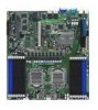
2.2.4 Motherboard layouts KFSN4-DRE/SAS model 33cm (13in) PS/2 T: Mouse B: Keyboard USB1 USB2 REAR_FAN4 PSUSMB1 PRI_IDE1 SEC_IDE1 ATXPWR1 ATX12V1 SATA2 SATA1 SATA4 SATA3 COM1 REAR_FAN3 REAR_FAN2 REAR_FAN1 FAN_SEL1 LAN1_EN1 ... module) DDR2 DIMM_B1 (64/72 bit, 240-pin module) DDR2 DIMM_A1 (64/72 bit, 240-pin module) FRNT_FAN5 FRNT_FAN6 VGA1 LAN1 BCM 5721 CPU1 ® KFSN4-DRE/SAS LAN2 BUZZ1 BCM 5721 CR2032 3V Lithium Cell CMOS Power CLRTC1 MEM_WARN1 AMI 8Mb FWH PCIE1 RECOVERY1 VGA_EN1 XGI Z9S LSI SAS1064E Super I/O SAS_EN1...
2.2.4 Motherboard layouts KFSN4-DRE/SAS model 33cm (13in) PS/2 T: Mouse B: Keyboard USB1 USB2 REAR_FAN4 PSUSMB1 PRI_IDE1 SEC_IDE1 ATXPWR1 ATX12V1 SATA2 SATA1 SATA4 SATA3 COM1 REAR_FAN3 REAR_FAN2 REAR_FAN1 FAN_SEL1 LAN1_EN1 ... module) DDR2 DIMM_B1 (64/72 bit, 240-pin module) DDR2 DIMM_A1 (64/72 bit, 240-pin module) FRNT_FAN5 FRNT_FAN6 VGA1 LAN1 BCM 5721 CPU1 ® KFSN4-DRE/SAS LAN2 BUZZ1 BCM 5721 CR2032 3V Lithium Cell CMOS Power CLRTC1 MEM_WARN1 AMI 8Mb FWH PCIE1 RECOVERY1 VGA_EN1 XGI Z9S LSI SAS1064E Super I/O SAS_EN1...

User Manual
Page 29
... the socket and the socket contacts are not bent. Locate the CPU socket on your left. ® ASUS KFSN4-DRE Series 2-9 ASUS shoulders the repair cost only if the damage is on the motherboard. CPU1 CPU1 CPU2 KFSN4-DRE Series CPU Socket 1207 Before installing the CPU, make sure that the socket box is facing toward you...
... the socket and the socket contacts are not bent. Locate the CPU socket on your left. ® ASUS KFSN4-DRE Series 2-9 ASUS shoulders the repair cost only if the damage is on the motherboard. CPU1 CPU1 CPU2 KFSN4-DRE Series CPU Socket 1207 Before installing the CPU, make sure that the socket box is facing toward you...

User Manual
Page 33
... Pins 112 Pins DIMM_B4 DIMM_A4 DIMM_B3 DIMM_A3 DIMM_B2 DIMM_A2 DIMM_B1 DIMM_A1 DIMM_C1 DIMM_D1 DIMM_C2 DIMM_D2 DIMM_C3 DIMM_D3 DIMM_C4 DIMM_D4 ASUS KFSN4-DRE Series 2-13 DDR2 DIMMs are notched differently to the 184-pin DDR DIMM. 2.4 System memory 2.4.1 Overview The motherboard comes with sixteen (16) Double Data Rate 2 (DDR2) Dual Inline Memory Modules (DIMM) sockets.
... Pins 112 Pins DIMM_B4 DIMM_A4 DIMM_B3 DIMM_A3 DIMM_B2 DIMM_A2 DIMM_B1 DIMM_A1 DIMM_C1 DIMM_D1 DIMM_C2 DIMM_D2 DIMM_C3 DIMM_D3 DIMM_C4 DIMM_D4 ASUS KFSN4-DRE Series 2-13 DDR2 DIMMs are notched differently to the 184-pin DDR DIMM. 2.4 System memory 2.4.1 Overview The motherboard comes with sixteen (16) Double Data Rate 2 (DDR2) Dual Inline Memory Modules (DIMM) sockets.

User Manual
Page 35
...Firmly insert the DIMM into a socket to avoid damaging the DIMM. • The DDR2 DIMM sockets do so can cause severe damage to both the motherboard and the components. Do not force a DIMM into the 1 socket until the retaining clips snap back in place and the DIMM is properly seated. ...the break on the socket such that it flips out with your fingers when pressing the 1 retaining clips. Remove the DIMM from the socket. ASUS KFSN4-DRE Series 2-15 The DIMM might get damaged when it fits in only one direction. To install a DIMM: 1. Simultaneously press the retaining clips ...
...Firmly insert the DIMM into a socket to avoid damaging the DIMM. • The DDR2 DIMM sockets do so can cause severe damage to both the motherboard and the components. Do not force a DIMM into the 1 socket until the retaining clips snap back in place and the DIMM is properly seated. ...the break on the socket such that it flips out with your fingers when pressing the 1 retaining clips. Remove the DIMM from the socket. ASUS KFSN4-DRE Series 2-15 The DIMM might get damaged when it fits in only one direction. To install a DIMM: 1. Simultaneously press the retaining clips ...

User Manual
Page 36
Failure to the chassis with the screw you removed earlier. 6. Remove the system unit cover (if your motherboard is completely seated on the slot. 5. Secure the card to do not need to use . 4. Replace the system cover. 2.5.2 Configuring an expansion card... is already installed in a chassis). 3. Turn on the next page. 3. 2.5 Expansion slots In the future, you may cause you physical injury and damage motherboard components. 2.5.1 Installing an expansion card To install an expansion card: 1. Align the card connector with it by adjusting the software settings. 1. The following sub&#...
Failure to the chassis with the screw you removed earlier. 6. Remove the system unit cover (if your motherboard is completely seated on the slot. 5. Secure the card to do not need to use . 4. Replace the system cover. 2.5.2 Configuring an expansion card... is already installed in a chassis). 3. Turn on the next page. 3. 2.5 Expansion slots In the future, you may cause you physical injury and damage motherboard components. 2.5.1 Installing an expansion card To install an expansion card: 1. Align the card connector with it by adjusting the software settings. 1. The following sub&#...

User Manual
Page 38
... (x8 link or x16 link) This motherboard supports PCI Express x16 cards that comply with one PCIE x 16 slot (x 16link). 2.5.5 BMC socket The BMC socket socket on the motherboard supports an ASUS® Server Management Board 3 Series (ASMB3). ® KFSN4-DRE Series BMC SOCKET 2-18 Chapter 2: Hardware information KFSN4-DRE Series PCI Express slot The number of...
... (x8 link or x16 link) This motherboard supports PCI Express x16 cards that comply with one PCIE x 16 slot (x 16link). 2.5.5 BMC socket The BMC socket socket on the motherboard supports an ASUS® Server Management Board 3 Series (ASMB3). ® KFSN4-DRE Series BMC SOCKET 2-18 Chapter 2: Hardware information KFSN4-DRE Series PCI Express slot The number of...

User Manual
Page 42
... allows you download the correct BIOS for the motherboard and the AFUDOS utility. Turn on the system to quickly update or recover the BIOS settings when it becomes corrupted. Insert the floppy disk then turn on the system. ® RECOVERY1 12 23 Disable (Default) KFSN4-DRE Series BIOS recovery setting Enable 2-22 Chapter...
... allows you download the correct BIOS for the motherboard and the AFUDOS utility. Turn on the system to quickly update or recover the BIOS settings when it becomes corrupted. Insert the floppy disk then turn on the system. ® RECOVERY1 12 23 Disable (Default) KFSN4-DRE Series BIOS recovery setting Enable 2-22 Chapter...

User Manual
Page 44
KFSN4-DRE Series Floppy disk drive connector 2. There are for Ultra DMA 133/100/66 signal cables. Drive jumper setting Single device Two devices Cable-Select or ... cable to match the covered hole on each Ultra DMA 133/100/66 signal cable: blue, black, and gray. Connect the blue connector to the motherboard's IDE connector, then select one end of the following modes to PIN 1. Floppy disk drive connector (34-1 pin FLOPPY1) This connector is set as "Cable...
KFSN4-DRE Series Floppy disk drive connector 2. There are for Ultra DMA 133/100/66 signal cables. Drive jumper setting Single device Two devices Cable-Select or ... cable to match the covered hole on each Ultra DMA 133/100/66 signal cable: blue, black, and gray. Connect the blue connector to the motherboard's IDE connector, then select one end of the following modes to PIN 1. Floppy disk drive connector (34-1 pin FLOPPY1) This connector is set as "Cable...


