K8N-E Deluxe User's Manual
Page 15
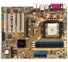
ASUS K8N-E Deluxe motherboard 1-1 Supporting up to set a new benchmark for an effective desktop ...for Ultra DMA 133/100/66 IDE drives 1 x 40-conductor IDE cable 1 x Ribbon cable for buying the ASUS® K8N-E Deluxe motherboard! Before you start installing the motherboard, and hardware devices on it another standout in your package with PC3200/...174; WinDVD Suite® (Retail boxes only) I/O shield Bag of extra jumper caps User guide If any of ASUS quality motherboards! Thank you ahead in the world of power computing! The motherboard delivers a host of new features and ...
ASUS K8N-E Deluxe motherboard 1-1 Supporting up to set a new benchmark for an effective desktop ...for Ultra DMA 133/100/66 IDE drives 1 x 40-conductor IDE cable 1 x Ribbon cable for buying the ASUS® K8N-E Deluxe motherboard! Before you start installing the motherboard, and hardware devices on it another standout in your package with PC3200/...174; WinDVD Suite® (Retail boxes only) I/O shield Bag of extra jumper caps User guide If any of ASUS quality motherboards! Thank you ahead in the world of power computing! The motherboard delivers a host of new features and ...
K8N-E Deluxe User's Manual
Page 17
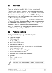
..., printers,TVs, and digital cameras. The higher bandwidth of USB 2.0 allows connection of peripherals and devices compliant to a fast 480 Mbps on Motherboard (LOM) applications. ASUS K8N-E Deluxe motherboard 1-3 USB 2.0 technology The motherboard implements the new Universal Serial Bus (USB) 2.0 specification, extending the connection speed from 12 Mbps on USB 1.1 to IEEE 1394a...
..., printers,TVs, and digital cameras. The higher bandwidth of USB 2.0 allows connection of peripherals and devices compliant to a fast 480 Mbps on Motherboard (LOM) applications. ASUS K8N-E Deluxe motherboard 1-3 USB 2.0 technology The motherboard implements the new Universal Serial Bus (USB) 2.0 specification, extending the connection speed from 12 Mbps on USB 1.1 to IEEE 1394a...

K8N-E Deluxe User's Manual
Page 19
feature of your choice from a floppy disk. Simply reboot the system to overclocking. See page 4-12. ASUS K8N-E Deluxe motherboard 1-5 ASUS Multi-language BIOS The multi-language BIOS allows you to playback audio files even without booting the system to configure easier and faster. ... BIOS allows automatic re-setting to the BIOS default settings in case the system hangs due to restore previously saved BIOS settings. Just press the ASUS Instant Music special function keys and enjoy the music! See pages 4-15, 5-11. See page 4-4. No need to use a DOS-based utility or...
feature of your choice from a floppy disk. Simply reboot the system to overclocking. See page 4-12. ASUS K8N-E Deluxe motherboard 1-5 ASUS Multi-language BIOS The multi-language BIOS allows you to playback audio files even without booting the system to configure easier and faster. ... BIOS allows automatic re-setting to the BIOS default settings in case the system hangs due to restore previously saved BIOS settings. Just press the ASUS Instant Music special function keys and enjoy the music! See pages 4-15, 5-11. See page 4-4. No need to use a DOS-based utility or...

K8N-E Deluxe User's Manual
Page 22
Chapter summary 2.1 Before you proceed 2-1 2.2 Motherboard overview 2-2 2.3 Central Processing Unit (CPU 2-6 2.4 System memory 2-11 2.5 Expansion slots 2-14 2.6 Jumpers 2-18 2.7 Connectors 2-20 ASUS K8N-E Deluxe motherboard
Chapter summary 2.1 Before you proceed 2-1 2.2 Motherboard overview 2-2 2.3 Central Processing Unit (CPU 2-6 2.4 System memory 2-11 2.5 Expansion slots 2-14 2.6 Jumpers 2-18 2.7 Connectors 2-20 ASUS K8N-E Deluxe motherboard

K8N-E Deluxe User's Manual
Page 23
... or remove any component, ensure that came with a standby power LED. 2.1 Before you proceed Note of the onboard LED. ® K8N-E K8N-E Onboard LED SB_PWR ON Standby Power OFF Powered Off ASUS K8N-E Deluxe motherboard 2-1 The illustration below shows the location of the following precautions before you install motherboard components or change any motherboard component...
... or remove any component, ensure that came with a standby power LED. 2.1 Before you proceed Note of the onboard LED. ® K8N-E K8N-E Onboard LED SB_PWR ON Standby Power OFF Powered Off ASUS K8N-E Deluxe motherboard 2-1 The illustration below shows the location of the following precautions before you install motherboard components or change any motherboard component...
K8N-E Deluxe User's Manual
Page 25
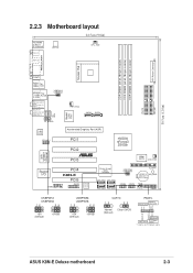
...+ PLED+5V Ground Ground Speaker PANEL Speaker Power LED Connector Reset SW ATX Power IDE_LED Switch* * Requires an ATX power supply. ASUS K8N-E Deluxe motherboard 2-3 PRI_IDE SEC_IDE 30.5cm (12.0in) 2.2.3 Motherboard layout 24.5cm (9.6in) PS/2KBMS T: Mouse B: Keyboard SPDIF_O1 ATX12V ... IE1394_2 Accelerated Graphics Port (AGP) PCI1 PCI2 ® PCI3 nVIDIA nForce3 250Gb 4Mbit BIOS CHA_FAN Super I/O COM2 PCI4 K8N-E PCI5 GAME Speech Controller Silicon Image SATA Controller SATA_RAID1 SATA_RAID3 SATA_RAID2 SATA_RAID4 USBPW56 USBPW78 FLOPPY CR2032 3V SB_PWR Lithium Cell CMOS...
...+ PLED+5V Ground Ground Speaker PANEL Speaker Power LED Connector Reset SW ATX Power IDE_LED Switch* * Requires an ATX power supply. ASUS K8N-E Deluxe motherboard 2-3 PRI_IDE SEC_IDE 30.5cm (12.0in) 2.2.3 Motherboard layout 24.5cm (9.6in) PS/2KBMS T: Mouse B: Keyboard SPDIF_O1 ATX12V ... IE1394_2 Accelerated Graphics Port (AGP) PCI1 PCI2 ® PCI3 nVIDIA nForce3 250Gb 4Mbit BIOS CHA_FAN Super I/O COM2 PCI4 K8N-E PCI5 GAME Speech Controller Silicon Image SATA Controller SATA_RAID1 SATA_RAID3 SATA_RAID2 SATA_RAID4 USBPW56 USBPW78 FLOPPY CR2032 3V SB_PWR Lithium Cell CMOS...
K8N-E Deluxe User's Manual
Page 27
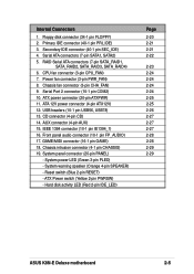
... activity LED (Red 2-pin IDE_LED) Page 2-20 2-21 2-21 2-22 2-23 2-24 2-24 2-24 2-24 2-25 2-25 2-26 2-27 2-27 2-27 2-28 2-28 2-29 2-29 ASUS K8N-E Deluxe motherboard 2-5 Internal Connectors 1. Primary IDE connector (40-1 pin PRI_IDE) 3. RAID Serial ATA connectors (7-pin SATA_RAID1, SATA_RAID2, SATA_RAID3, SATA_RAID4) 6. System power LED (Green 3-pin PLED) - Power...
... activity LED (Red 2-pin IDE_LED) Page 2-20 2-21 2-21 2-22 2-23 2-24 2-24 2-24 2-24 2-25 2-25 2-26 2-27 2-27 2-27 2-28 2-28 2-29 2-29 ASUS K8N-E Deluxe motherboard 2-5 Internal Connectors 1. Primary IDE connector (40-1 pin PRI_IDE) 3. RAID Serial ATA connectors (7-pin SATA_RAID1, SATA_RAID2, SATA_RAID3, SATA_RAID4) 6. System power LED (Green 3-pin PLED) - Power...

K8N-E Deluxe User's Manual
Page 29
... socket lever to indicate that it is lifted up to a 90°-100° angle. Small triangle Gold triangle The CPU fits only in place. ASUS K8N-E Deluxe motherboard 2-7 The lever clicks on the side tab to secure the CPU. 2. When the CPU is in completely. 3. Position the CPU above the socket such...
... socket lever to indicate that it is lifted up to a 90°-100° angle. Small triangle Gold triangle The CPU fits only in place. ASUS K8N-E Deluxe motherboard 2-7 The lever clicks on the side tab to secure the CPU. 2. When the CPU is in completely. 3. Position the CPU above the socket such...

K8N-E Deluxe User's Manual
Page 31
2. Attach one end of the retention bracket (near the retention bracket lock) to the retention module base. Push down the retention bracket lock on the retention mechanism to secure the heatsink and fan to the retention module base. 3. Align the other end of the retention bracket to the module base. Make sure that the retention bracket is in place. 4. A clicking sound denotes that the fan and heatsink assembly perfectly fits the retention mechanism module base, otherwise you cannot snap the retention bracket in place. ASUS K8N-E Deluxe motherboard 2-9
2. Attach one end of the retention bracket (near the retention bracket lock) to the retention module base. Push down the retention bracket lock on the retention mechanism to secure the heatsink and fan to the retention module base. 3. Align the other end of the retention bracket to the module base. Make sure that the retention bracket is in place. 4. A clicking sound denotes that the fan and heatsink assembly perfectly fits the retention mechanism module base, otherwise you cannot snap the retention bracket in place. ASUS K8N-E Deluxe motherboard 2-9

K8N-E Deluxe User's Manual
Page 33
... three Double Data Rate (DDR) Dual Inline Memory Module (DIMM) sockets. DIMM1 DIMM2 DIMM3 104 Pins 80 Pins ® K8V-E K8N-E 184-Pin DDR DIMM Sockets 2.4.2 Memory configurations You may cause memory sizing error or system boot failure. ASUS K8N-E Deluxe motherboard 2-11 2.4 System memory 2.4.1 Overview The motherboard comes with the same CAS Latency.
... three Double Data Rate (DDR) Dual Inline Memory Module (DIMM) sockets. DIMM1 DIMM2 DIMM3 104 Pins 80 Pins ® K8V-E K8N-E 184-Pin DDR DIMM Sockets 2.4.2 Memory configurations You may cause memory sizing error or system boot failure. ASUS K8N-E Deluxe motherboard 2-11 2.4 System memory 2.4.1 Overview The motherboard comes with the same CAS Latency.

K8N-E Deluxe User's Manual
Page 35
... a DIMM into the socket until the retaining clips snap back in only one direction. Firmly insert the DIMM into a socket to avoid damaging the DIMM. 3. ASUS K8N-E Deluxe motherboard 2-13 Unlock a DIMM socket by pressing the retaining clips outward. 2. Support the DIMM lightly with extra force. 2. The DIMM might get damaged when it...
... a DIMM into the socket until the retaining clips snap back in only one direction. Firmly insert the DIMM into a socket to avoid damaging the DIMM. 3. ASUS K8N-E Deluxe motherboard 2-13 Unlock a DIMM socket by pressing the retaining clips outward. 2. Support the DIMM lightly with extra force. 2. The DIMM might get damaged when it...
K8N-E Deluxe User's Manual
Page 37
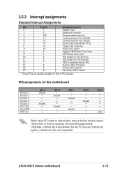
INT B - shared - - - Otherwise, conflicts will arise between the two PCI groups, making the system unstable and the card inoperable. INT C - - shared - - - - ASUS K8N-E Deluxe motherboard 2-15 INT E used 10* 5 IRQ Holder for PCI Steering 11* 6 IRQ Holder for PCI Steering 12* 7 PS/2 Compatible Mouse Port 13 8 Numeric Data Processor ...
INT B - shared - - - Otherwise, conflicts will arise between the two PCI groups, making the system unstable and the card inoperable. INT C - - shared - - - - ASUS K8N-E Deluxe motherboard 2-15 INT E used 10* 5 IRQ Holder for PCI Steering 11* 6 IRQ Holder for PCI Steering 12* 7 PS/2 Compatible Mouse Port 13 8 Numeric Data Processor ...

K8N-E Deluxe User's Manual
Page 39
... jumper from pins 1-2 (default) to pins 1-2. 4. Replace the battery. 5. Load the BIOS default settings or key-in data. ® K8V-E K8N-E Clear RTC RAM CLRTC 12 23 Normal (Default) Clear CMOS ASUS K8N-E Deluxe motherboard 2-17 Hold down the key during the boot process and enter BIOS setup menu. 7. You can clear the CMOS...
... jumper from pins 1-2 (default) to pins 1-2. 4. Replace the battery. 5. Load the BIOS default settings or key-in data. ® K8V-E K8N-E Clear RTC RAM CLRTC 12 23 Normal (Default) Clear CMOS ASUS K8N-E Deluxe motherboard 2-17 Hold down the key during the boot process and enter BIOS setup menu. 7. You can clear the CMOS...
K8N-E Deluxe User's Manual
Page 41
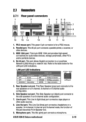
... devices. 4. Microphone port. Line Out port. Rear Speaker out port. Line In port. This Line In (light blue) port connects a tape player or other devices. 3. ASUS K8N-E Deluxe motherboard 2-19 This 6-pin IEEE 1394 port provides high-speed connectivity for a PS/2 mouse. 2. PS/2 mouse port.
... devices. 4. Microphone port. Line Out port. Rear Speaker out port. Line In port. This Line In (light blue) port connects a tape player or other devices. 3. ASUS K8N-E Deluxe motherboard 2-19 This 6-pin IEEE 1394 port provides high-speed connectivity for a PS/2 mouse. 2. PS/2 mouse port.

K8N-E Deluxe User's Manual
Page 43
PIN 1 ASUS K8N-E Deluxe motherboard 2-21 IDE connectors (40-1 pin PRI_IDE, SEC_IDE) This connector supports the provided UltraDMA IDE hard disk ribbon cable. Connect the cable's blue connector to ... device in master or slave mode. • Pin 20 on the UltraDMA cable connector. This prevents incorrect orientation when you connect the cables. ® K8V-E K8N-E IDE Connectors PRI_IDE SEC_IDE NOTE: Orient the red markings (usually zigzag) on the IDE ribbon cable to match the covered hole on each IDE connector...
PIN 1 ASUS K8N-E Deluxe motherboard 2-21 IDE connectors (40-1 pin PRI_IDE, SEC_IDE) This connector supports the provided UltraDMA IDE hard disk ribbon cable. Connect the cable's blue connector to ... device in master or slave mode. • Pin 20 on the UltraDMA cable connector. This prevents incorrect orientation when you connect the cables. ® K8V-E K8N-E IDE Connectors PRI_IDE SEC_IDE NOTE: Orient the red markings (usually zigzag) on the IDE ribbon cable to match the covered hole on each IDE connector...

K8N-E Deluxe User's Manual
Page 45
...; Sil 3114 RAID controller, you can configure as a RAID set using the SATALink™ SATA RAID Management Software only. ASUS K8N-E Deluxe motherboard 2-23 RAID Serial ATA connectors (7-pin SATA_RAID1, SATA_RAID2, SATA_RAID3, SATA_RAID4) These Serial ATA connectors support SATA hard disks that...GND RSATA_RXP1 RSATA_RXN1 GND ® K8V-E SATA_RAID2 SATA_RAID4 GND RSATA_TXP2 RSATA_TXN2 GND RSATA_RXP2 RSATA_RXN2 GND GND RSATA_TXP2 RSATA_TXN2 GND RSATA_RXP2 RSATA_RXN2 GND K8N-E SATA RAID Connectors • To create a RAID set, make sure that you can be set . See Chapter 5 for ...
...; Sil 3114 RAID controller, you can configure as a RAID set using the SATALink™ SATA RAID Management Software only. ASUS K8N-E Deluxe motherboard 2-23 RAID Serial ATA connectors (7-pin SATA_RAID1, SATA_RAID2, SATA_RAID3, SATA_RAID4) These Serial ATA connectors support SATA hard disks that...GND RSATA_RXP1 RSATA_RXN1 GND ® K8V-E SATA_RAID2 SATA_RAID4 GND RSATA_TXP2 RSATA_TXN2 GND RSATA_RXP2 RSATA_RXN2 GND GND RSATA_TXP2 RSATA_TXN2 GND RSATA_RXP2 RSATA_RXN2 GND K8N-E SATA RAID Connectors • To create a RAID set, make sure that you can be set . See Chapter 5 for ...

K8N-E Deluxe User's Manual
Page 47
... Connectors ATXPWR Pin 1 +12.0VDC +5VSB PWR_OK COM +5.0VDC COM +5.0VDC COM +3.3VDC +3.3VDC +5.0VDC +5.0VDC -5.0VDC COM COM COM PS_ON# COM -12.0VDC +3.3VDC ASUS K8N-E Deluxe motherboard 2-25 The plugs from the power supply are for a fully configured system. Find the proper orientation and push down firmly until the connectors completely...
... Connectors ATXPWR Pin 1 +12.0VDC +5VSB PWR_OK COM +5.0VDC COM +5.0VDC COM +3.3VDC +3.3VDC +5.0VDC +5.0VDC -5.0VDC COM COM COM PS_ON# COM -12.0VDC +3.3VDC ASUS K8N-E Deluxe motherboard 2-25 The plugs from the power supply are for a fully configured system. Find the proper orientation and push down firmly until the connectors completely...

K8N-E Deluxe User's Manual
Page 49
Attach the 10-1 pin cable plug to this connector. Doing so will damage the motherboard! ASUS K8N-E Deluxe motherboard 2-27 TPA0GND TPB0+12V GND ® K8V-E K8N-E IEEE-1394 Connector IE1394_2 1 TPA0+ GND TPB0+ +12V NEVER connect a USB cable to receive stereo audio input from sound sources such... as a CD-ROM, TV tuner, or MPEG card. ® K8V-E CD (Black) AUX (White) Right Audio Channel Ground Left Audio Channel K8N-E Internal Audio Connectors 10. You can also connect a 1394-compliant internal hard disk to this connector. 9. IEEE 1394 connectors (10-1 pin IE1394_2) ...
Attach the 10-1 pin cable plug to this connector. Doing so will damage the motherboard! ASUS K8N-E Deluxe motherboard 2-27 TPA0GND TPB0+12V GND ® K8V-E K8N-E IEEE-1394 Connector IE1394_2 1 TPA0+ GND TPB0+ +12V NEVER connect a USB cable to receive stereo audio input from sound sources such... as a CD-ROM, TV tuner, or MPEG card. ® K8V-E CD (Black) AUX (White) Right Audio Channel Ground Left Audio Channel K8N-E Internal Audio Connectors 10. You can also connect a 1394-compliant internal hard disk to this connector. 9. IEEE 1394 connectors (10-1 pin IE1394_2) ...

K8N-E Deluxe User's Manual
Page 51
...lead is color-coded for a chassis designed with a jumper cap. CHASSIS +5VSB_MB Chassis Signal GND ® K8V-E K8N-E Chassis Alarm Lead (Default) 14. To use the chassis intrusion detection feature, remove the jumper cap from the pins...Ground Reset Ground ® Reset SW ATX Power K8V-E IDE_LED Switch* * Requires an ATX power supply. K8N-E System Panel Connector The System Panel connector is for easy and foolproof connection. This requires an external detection... specific connector colors as a chassis intrusion sensor or microswitch. ASUS K8N-E Deluxe motherboard 2-29
...lead is color-coded for a chassis designed with a jumper cap. CHASSIS +5VSB_MB Chassis Signal GND ® K8V-E K8N-E Chassis Alarm Lead (Default) 14. To use the chassis intrusion detection feature, remove the jumper cap from the pins...Ground Reset Ground ® Reset SW ATX Power K8V-E IDE_LED Switch* * Requires an ATX power supply. K8N-E System Panel Connector The System Panel connector is for easy and foolproof connection. This requires an external detection... specific connector colors as a chassis intrusion sensor or microswitch. ASUS K8N-E Deluxe motherboard 2-29

K8N-E Deluxe User's Manual
Page 54
Chapter summary 3.1 Starting up for the first time 3-1 3.2 Powering off the computer 3-2 3.3 ASUS POST Reporter 3-3 ASUS K8N-E Deluxe motherboard
Chapter summary 3.1 Starting up for the first time 3-1 3.2 Powering off the computer 3-2 3.3 ASUS POST Reporter 3-3 ASUS K8N-E Deluxe motherboard


