User Guide
Page 3
... viii Typography ix K8N-DL specifications summary x Chapter 1: Product introduction 1.1 Welcome 1-1 1.2 Package contents 1-1 1.3 Special features 1-2 1.3.1 Product highlights 1-2 1.3.2 Innovative ASUS features 1-4 Chapter 2: Hardware information 2.1 Before you proceed 2-1 2.2 Motherboard overview 2-3 2.2.1 Placement direction 2-3 2.2.2 Screw holes 2-3 2.2.3 Motherboard layout 2-4 2.2.4 Layout Contents 2-5 2.3.2 Installing the CPU 2-7 2.3 Central Processing Unit (CPU 2-7 2.3.1 Overview 2-7 2.3.3 Installing the heatsink and fan 2-9 2.4 System memory 2-11 2.4.1 Overview 2-11...
... viii Typography ix K8N-DL specifications summary x Chapter 1: Product introduction 1.1 Welcome 1-1 1.2 Package contents 1-1 1.3 Special features 1-2 1.3.1 Product highlights 1-2 1.3.2 Innovative ASUS features 1-4 Chapter 2: Hardware information 2.1 Before you proceed 2-1 2.2 Motherboard overview 2-3 2.2.1 Placement direction 2-3 2.2.2 Screw holes 2-3 2.2.3 Motherboard layout 2-4 2.2.4 Layout Contents 2-5 2.3.2 Installing the CPU 2-7 2.3 Central Processing Unit (CPU 2-7 2.3.1 Overview 2-7 2.3.3 Installing the heatsink and fan 2-9 2.4 System memory 2-11 2.4.1 Overview 2-11...

User Guide
Page 4
...BIOS 4-1 4.1.1 Creating a bootable floppy disk 4-1 4.1.2 Updating the BIOS 4-2 4.1.3 Saving the current BIOS file 4-4 4.1.4 ASUS CrashFree BIOS 2 utility 4-5 4.1.5 ASUS EZ Flash utility 4-7 4.1.6 ASUS Update utility 4-8 4.2 BIOS setup program 4-11 4.2.1 BIOS menu screen 4-12 4.2.2 Menu bar 4-12 4.2.3 Legend bar ... System Time 4-15 4.3.2 System Date 4-15 4.3.3 Legacy Diskette A 4-15 4.3.4 Floppy 3 Mode Support 4-15 4.3.5 Base/Extended/Total Memory 4-15 4.3.6 Primary IDE Master 4-16 4.3.7 Primary IDE Slave 4-18 4.3.8 Secondary IDE Master 4-18 4.3.9 Secondary IDE Slave 4-18 4.3....
...BIOS 4-1 4.1.1 Creating a bootable floppy disk 4-1 4.1.2 Updating the BIOS 4-2 4.1.3 Saving the current BIOS file 4-4 4.1.4 ASUS CrashFree BIOS 2 utility 4-5 4.1.5 ASUS EZ Flash utility 4-7 4.1.6 ASUS Update utility 4-8 4.2 BIOS setup program 4-11 4.2.1 BIOS menu screen 4-12 4.2.2 Menu bar 4-12 4.2.3 Legend bar ... System Time 4-15 4.3.2 System Date 4-15 4.3.3 Legacy Diskette A 4-15 4.3.4 Floppy 3 Mode Support 4-15 4.3.5 Base/Extended/Total Memory 4-15 4.3.6 Primary IDE Master 4-16 4.3.7 Primary IDE Slave 4-18 4.3.8 Secondary IDE Master 4-18 4.3.9 Secondary IDE Slave 4-18 4.3....
User Guide
Page 5
Contents 4.4 Advanced menu 4-20 4.4.1 CPU Configuration 4-20 4.4.2 Memory Configuration 4-21 4.4.3 Chipset 4-23 4.4.4 Onboard Device 4-26 4.4.5 PCIPnP 4-30 4.4.6 USB Configuration 4-32 4.5 Power menu 4-33 4.5.1 APM Configuration 4-34 4.5.2 Hardware Monitor 4-36 4.6 Boot menu 4-39 4.6.1 Boot Device Priority 4-39 4.6.2 Hard Disk Boot Priority 4-40 4.6.3 Removable Device Priority 4-40 4.6.4 Boot Settings Configuration 4-41 4.6.5 Security 4-43 4.7 Exit menu 4-45 Appendix: Reference information A.1 K8N-DL block diagram A-1 v
Contents 4.4 Advanced menu 4-20 4.4.1 CPU Configuration 4-20 4.4.2 Memory Configuration 4-21 4.4.3 Chipset 4-23 4.4.4 Onboard Device 4-26 4.4.5 PCIPnP 4-30 4.4.6 USB Configuration 4-32 4.5 Power menu 4-33 4.5.1 APM Configuration 4-34 4.5.2 Hardware Monitor 4-36 4.6 Boot menu 4-39 4.6.1 Boot Device Priority 4-39 4.6.2 Hard Disk Boot Priority 4-40 4.6.3 Removable Device Priority 4-40 4.6.4 Boot Settings Configuration 4-41 4.6.5 Security 4-43 4.7 Exit menu 4-45 Appendix: Reference information A.1 K8N-DL block diagram A-1 v
User Guide
Page 10
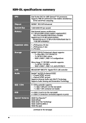
...; ASUS EZFlash ASUS Smart Fan Technology ASUS CrashFree BIOS 2 ASUS MyLogo2 (continued on this motherboard due to 4 GB DDR availability) 1 x PCI Express x16 slot 1 x PCI Express x1 slot 2 x PCI slots NVIDIA® CK8-04 Professional chipset supports: - 2 x Ultra DMA 133/100/66/33 - 4 x SATA-II 3Gb/s drives - K8N-DL specifications summary CPU Chipset System Bus Memory Expansion...
...; ASUS EZFlash ASUS Smart Fan Technology ASUS CrashFree BIOS 2 ASUS MyLogo2 (continued on this motherboard due to 4 GB DDR availability) 1 x PCI Express x16 slot 1 x PCI Express x1 slot 2 x PCI slots NVIDIA® CK8-04 Professional chipset supports: - 2 x Ultra DMA 133/100/66/33 - 4 x SATA-II 3Gb/s drives - K8N-DL specifications summary CPU Chipset System Bus Memory Expansion...

User Guide
Page 16
...3Gb/s technology through the Serial ATA interfaces and the NVIDIA® nForce4® PRO chipset. Dual Channel DDR memory support Employing the Double Data Rate (DDR) memory technology, the motherboard supports up the PCI bus. The SATA 3Gb/s specification provides twice the bandwidth of ownership and... processors are based on AMD's 64-bit and 32-bit architecture, which represents the landmark introduction of system memory using DDR400/333/ 266 DIMMs. The ultra-fast 400MHz memory bus delivers the required bandwidth for details. This high speed interface is a high-speed, low latency, point...
...3Gb/s technology through the Serial ATA interfaces and the NVIDIA® nForce4® PRO chipset. Dual Channel DDR memory support Employing the Double Data Rate (DDR) memory technology, the motherboard supports up the PCI bus. The SATA 3Gb/s specification provides twice the bandwidth of ownership and... processors are based on AMD's 64-bit and 32-bit architecture, which represents the landmark introduction of system memory using DDR400/333/ 266 DIMMs. The ultra-fast 400MHz memory bus delivers the required bandwidth for details. This high speed interface is a high-speed, low latency, point...
User Guide
Page 20
Chapter summary 2.1 Before you proceed 2-1 2.2 Motherboard overview 2-3 2.3 Central Processing Unit (CPU 2-7 2.4 System memory 2-11 2.5 Expansion slots 2-14 2.6 Jumpers 2-17 2.7 Connectors 2-20 ASUS K8N-DL
Chapter summary 2.1 Before you proceed 2-1 2.2 Motherboard overview 2-3 2.3 Central Processing Unit (CPU 2-7 2.4 System memory 2-11 2.5 Expansion slots 2-14 2.6 Jumpers 2-17 2.7 Connectors 2-20 ASUS K8N-DL
User Guide
Page 31
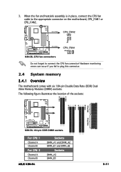
... Pins DIMM_A2 DIMM_B1 DIMM_A1 104 Pins ® K8N-DL K8N-DL 184-pin DDR DIMM sockets For CPU 1 Channel A Channel B For CPU 2 Channel A Channel B ASUS K8N-DL Sockets DIMM_A1 and DIMM_A2 DIMM_B1 and DIMM_B2 Sockets DIMM_A3 DIMM_B3 2-11 Hardware monitoring errors can occur if you fail to plug this connector. 2.4 System memory 2.4.1 Overview The motherboard comes with six...
... Pins DIMM_A2 DIMM_B1 DIMM_A1 104 Pins ® K8N-DL K8N-DL 184-pin DDR DIMM sockets For CPU 1 Channel A Channel B For CPU 2 Channel A Channel B ASUS K8N-DL Sockets DIMM_A1 and DIMM_A2 DIMM_B1 and DIMM_B2 Sockets DIMM_A3 DIMM_B3 2-11 Hardware monitoring errors can occur if you fail to plug this connector. 2.4 System memory 2.4.1 Overview The motherboard comes with six...

User Guide
Page 32
... or 4 GB registered ECC DDR DIMMs into the DIMM sockets using two DDR DIMM modules, install into DIMM_A1 slot only. • When using the memory configurations in 2000SER, 2003SER, or 64-bit operating systems. 2-12 Chapter 2: Hardware information Single CPU: DIMM_A1+DIMM_A2=DIMM_B1+DIMM_B2 Dual CPU: DIMM_A1+DIMM_A2=... details. • 4 GB DDR400 registered ECC DIMMs operate in this section. • For dual-channel configuration, the total size of memory module(s) installed per channel must be the same for better performance. For optimum compatibility, it is recommended that you obtain...
... or 4 GB registered ECC DDR DIMMs into the DIMM sockets using two DDR DIMM modules, install into DIMM_A1 slot only. • When using the memory configurations in 2000SER, 2003SER, or 64-bit operating systems. 2-12 Chapter 2: Hardware information Single CPU: DIMM_A1+DIMM_A2=DIMM_B1+DIMM_B2 Dual CPU: DIMM_A1+DIMM_A2=... details. • 4 GB DDR400 registered ECC DIMMs operate in this section. • For dual-channel configuration, the total size of memory module(s) installed per channel must be the same for better performance. For optimum compatibility, it is recommended that you obtain...
User Guide
Page 37
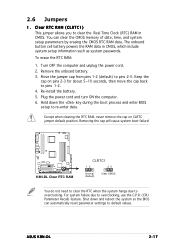
Re-install the battery. 5. Hold down and reboot the system so the BIOS can clear the CMOS memory of date, time, and system setup parameters by erasing the CMOS RTC RAM data. ASUS K8N-DL 2-17 Remove the onboard battery. 3. Move the jumper cap from pins 1-2 (default) to overclocking, use the C.P.R. (CPU ...process and enter BIOS setup to default values. For system failure due to pins 2-3. Removing the cap will cause system boot failure! ® K8N-DL K8N-DL Clear RTC RAM CLRTC1 12 23 Normal (Default) Clear CMOS You do not need to clear the RTC when the system hangs due to ...
Re-install the battery. 5. Hold down and reboot the system so the BIOS can clear the CMOS memory of date, time, and system setup parameters by erasing the CMOS RTC RAM data. ASUS K8N-DL 2-17 Remove the onboard battery. 3. Move the jumper cap from pins 1-2 (default) to overclocking, use the C.P.R. (CPU ...process and enter BIOS setup to default values. For system failure due to pins 2-3. Removing the cap will cause system boot failure! ® K8N-DL K8N-DL Clear RTC RAM CLRTC1 12 23 Normal (Default) Clear CMOS You do not need to clear the RTC when the system hangs due to ...
User Guide
Page 55
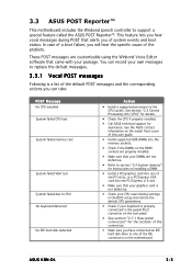
...memory test System failed VGA test System failed due to CPU No keyboard detected No IDE hard disk detected Action • Install a supported processor to replace the default messages. 3.3.1 Vocal POST messages Following is properly connected to support a special feature called the ASUS POST Reporter™. ASUS K8N-DL... 3-3 These POST messages are not defective. • Refer to section "2.4 System memory" for assistance.
...memory test System failed VGA test System failed due to CPU No keyboard detected No IDE hard disk detected Action • Install a supported processor to replace the default messages. 3.3.1 Vocal POST messages Following is properly connected to support a special feature called the ASUS POST Reporter™. ASUS K8N-DL... 3-3 These POST messages are not defective. • Refer to section "2.4 System memory" for assistance.

User Guide
Page 74
... IDE Master Primary IDE Slave Secondary IDE Master Secondary IDE Slave Third IDE Master Fourth IDE Master IDE Channel 4 Master IDE Channel 5 Master Base Memory Extended Memory Total Memory 15 : 30 : 36 Wed, Feb 2 2005 [1.44M, 3.5 in.] [Disabled] [None] [None] [None] [None] [None] [None] [None] [None] 256K 261120K 262144K Select Menu Item Specific...
... IDE Master Primary IDE Slave Secondary IDE Master Secondary IDE Slave Third IDE Master Fourth IDE Master IDE Channel 4 Master IDE Channel 5 Master Base Memory Extended Memory Total Memory 15 : 30 : 36 Wed, Feb 2 2005 [1.44M, 3.5 in.] [Disabled] [None] [None] [None] [None] [None] [None] [None] [None] 256K 261120K 262144K Select Menu Item Specific...
User Guide
Page 76
... in[.None]..... [ ] Third IDE Master 720K , 3.5 in.[None]..... [ ] Fourth IDE Master 1.44M, 3.5 in.[None]..... [ ] IDE Channel 4 Master2.88M, 3.5 in.[None]..... [ ] IDE Channel 5 Master [None] Base Memory Extended Memory Total Memory 256K ↑↓ :Move ENT2E6R1:1A2c0cKept ESC:Abort 262144K Select Menu Item Specific Help Change the internal clock.
... in[.None]..... [ ] Third IDE Master 720K , 3.5 in.[None]..... [ ] Fourth IDE Master 1.44M, 3.5 in.[None]..... [ ] IDE Channel 4 Master2.88M, 3.5 in.[None]..... [ ] IDE Channel 5 Master [None] Base Memory Extended Memory Total Memory 256K ↑↓ :Move ENT2E6R1:1A2c0cKept ESC:Abort 262144K Select Menu Item Specific Help Change the internal clock.
User Guide
Page 77
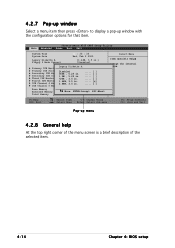
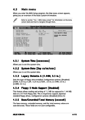
... IDE Master Primary IDE Slave Secondary IDE Master Secondary IDE Slave Third IDE Master Fourth IDE Master IDE Channel 4 Master IDE Channel 5 Master Base Memory Extended Memory Total Memory 15 : 30 : 36 Wed, Feb 2 2005 [1.44M, 3.5 in.] [Disabled] [None] [None] [None] [None] [None] [None] [None] [...basic system information. These fields are auto-detected. This is required to section "4.2.1 BIOS menu screen" for information on a 3.5-inch floppy disk. ASUS K8N-DL 4-15 4.3 Main menu When you enter the BIOS Setup program, the Main menu screen appears, giving you to set the system date. 4.3.3 ...
... IDE Master Primary IDE Slave Secondary IDE Master Secondary IDE Slave Third IDE Master Fourth IDE Master IDE Channel 4 Master IDE Channel 5 Master Base Memory Extended Memory Total Memory 15 : 30 : 36 Wed, Feb 2 2005 [1.44M, 3.5 in.] [Disabled] [None] [None] [None] [None] [None] [None] [None] [...basic system information. These fields are auto-detected. This is required to section "4.2.1 BIOS menu screen" for information on a 3.5-inch floppy disk. ASUS K8N-DL 4-15 4.3 Main menu When you enter the BIOS Setup program, the Main menu screen appears, giving you to set the system date. 4.3.3 ...
User Guide
Page 82
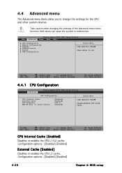
...: [Disabled] [Enabled] External Cache [Enabled] Disables or enables the CPU L3 cache. Phoenix-Award BIOS CMOS Setup Utility Main Advanced Power Boot Exit CPU Configuration Memory Configuration Chipset Onboard Device PCIPnP USB Configuration Select Menu Item Specific Help Press Enter to set F1:Help ESC: Exit ↑↓ : Select Item →...
...: [Disabled] [Enabled] External Cache [Enabled] Disables or enables the CPU L3 cache. Phoenix-Award BIOS CMOS Setup Utility Main Advanced Power Boot Exit CPU Configuration Memory Configuration Chipset Onboard Device PCIPnP USB Configuration Select Menu Item Specific Help Press Enter to set F1:Help ESC: Exit ↑↓ : Select Item →...
User Guide
Page 83
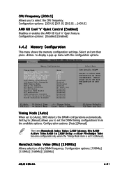
...'n' Quiet Control [Enabled] Disables or enables the AMD K8 Cool 'n' Quiet feature. Configuration options: [Disabled] [Enabled] 4.4.2 Memory Configuration This menu shows the memory configuration settings. Memory Configuration Timing Mode Memclock Index Value (Mhz) CAS# Latency (Tcl) Min RAS# Active Time (Tras) RAS# to CAS#...Memclock Index Value (Mhz) [200MHz] Allows selection of the DRAM frequency. Configuration options: [100Mhz] [133Mhz] [166Mhz] [200Mhz] ASUS K8N-DL 4-21 Select an item then press to select the CPU frequency. CPU Frequency [200.0] Allows you to display a pop-up menu ...
...'n' Quiet Control [Enabled] Disables or enables the AMD K8 Cool 'n' Quiet feature. Configuration options: [Disabled] [Enabled] 4.4.2 Memory Configuration This menu shows the memory configuration settings. Memory Configuration Timing Mode Memclock Index Value (Mhz) CAS# Latency (Tcl) Min RAS# Active Time (Tras) RAS# to CAS#...Memclock Index Value (Mhz) [200MHz] Allows selection of the DRAM frequency. Configuration options: [100Mhz] [133Mhz] [166Mhz] [200Mhz] ASUS K8N-DL 4-21 Select an item then press to select the CPU frequency. CPU Frequency [200.0] Allows you to display a pop-up menu ...

User Guide
Page 84
...command. Configuration options: [2T] [3T] [4T] [5T] [6T] [7T] Node Memory Interleaving [Disabled] Enables or disables memory interleaving. Configuration options: [Disabled] [Enabled] ECC Memory Interlock [At Least One] Allows selection for DRAM parameters. Configuration options: [Continuous] [Discreet...and the read command and the time the data actually becomes available. Configuration options: [Disabled] [Enabled] S/W Memory Hole Remapping [Enabled] Allows memory hoisting/remapping of [Continuous] for standard mode, or [Discreet] for aggressive mode. Configuration options: [2] [2.5] ...
...command. Configuration options: [2T] [3T] [4T] [5T] [6T] [7T] Node Memory Interleaving [Disabled] Enables or disables memory interleaving. Configuration options: [Disabled] [Enabled] ECC Memory Interlock [At Least One] Allows selection for DRAM parameters. Configuration options: [Continuous] [Discreet...and the read command and the time the data actually becomes available. Configuration options: [Disabled] [Enabled] S/W Memory Hole Remapping [Enabled] Allows memory hoisting/remapping of [Continuous] for standard mode, or [Discreet] for aggressive mode. Configuration options: [2] [2.5] ...

User Guide
Page 92
.... PCI/VGA Pallet Snoop [Disabled] Some non-standard VGA cards, like graphics accelerators or MPEG video cards, may not show colors properly. Memory Configuration Resources Controlled By IRQ Resources [Auto] PCI/VGA Pallete Snoop [Disabled] ** PCI Express relative items ** Maximum Payload Size [4096] ... the item IRQ Resources is set to enable this field to the default setting [Disabled]. If you cannot select IRQ DMA and memory base address fields, since BIOS automatically assigns them. Select an item then press to boot devices and Plug and Play devices. Configuration ...
.... PCI/VGA Pallet Snoop [Disabled] Some non-standard VGA cards, like graphics accelerators or MPEG video cards, may not show colors properly. Memory Configuration Resources Controlled By IRQ Resources [Auto] PCI/VGA Pallete Snoop [Disabled] ** PCI Express relative items ** Maximum Payload Size [4096] ... the item IRQ Resources is set to enable this field to the default setting [Disabled]. If you cannot select IRQ DMA and memory base address fields, since BIOS automatically assigns them. Select an item then press to boot devices and Plug and Play devices. Configuration ...
User Guide
Page 93
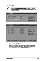
... n t r o l l e d B y to [Manual] to enable the item I R Q R e s o u r c e s and assign the interrupts depending on the type of PCI/PnP devices. Memory Configuration Resources Controlled By IRQ Resources [Manual] PCI/VGA Pallete Snoop [Disabled] ** PCI Express relative items ** Maximum Payload Size [4096] Select Menu Item Specific Help ...reserved for PCI or ISA bus architecture. Configuration options: [PCI Device] [Reserved] ASUS K8N-DL 4-31 If you choose Auto, you cannot select IRQ DMA and memory base address IRQ Resources IRQ-3 assigned to IRQ-4 assigned to IRQ-5 assigned to IRQ...
... n t r o l l e d B y to [Manual] to enable the item I R Q R e s o u r c e s and assign the interrupts depending on the type of PCI/PnP devices. Memory Configuration Resources Controlled By IRQ Resources [Manual] PCI/VGA Pallete Snoop [Disabled] ** PCI Express relative items ** Maximum Payload Size [4096] Select Menu Item Specific Help ...reserved for PCI or ISA bus architecture. Configuration options: [PCI Device] [Reserved] ASUS K8N-DL 4-31 If you choose Auto, you cannot select IRQ DMA and memory base address IRQ Resources IRQ-3 assigned to IRQ-4 assigned to IRQ-5 assigned to IRQ...


