
K7V-T User Manual
Page 4
HARDWARE SETUP 14 3.1 K7V-T Motherboard Layout 14 3.2 Layout Contents 15 3.3 Hardware Setup Procedure 17 3.4 Motherboard Settings 17 3.5 System Memory (DIMM 22 3.5.1 General DIMM Notes 22 3.5.2 DIMM Memory Installation 23 3.6 Central Processing Unit (CPU ...4.1.1 Upon First Use of the Computer System 49 4.1.2 Updating BIOS Procedures 50 4 ASUS K7V-T User's Manual INTRODUCTION 7 1.1 How This Manual Is Organized 7 1.2 Item Checklist 7 2. FEATURES 8 2.1 The ASUS K7V-T Motherboard 8 2.1.1 Specifications 8 2.1.1.1 Optional Components 9 2.1.2 Performance 10 2.1.3 Intelligence (...
HARDWARE SETUP 14 3.1 K7V-T Motherboard Layout 14 3.2 Layout Contents 15 3.3 Hardware Setup Procedure 17 3.4 Motherboard Settings 17 3.5 System Memory (DIMM 22 3.5.1 General DIMM Notes 22 3.5.2 DIMM Memory Installation 23 3.6 Central Processing Unit (CPU ...4.1.1 Upon First Use of the Computer System 49 4.1.2 Updating BIOS Procedures 50 4 ASUS K7V-T User's Manual INTRODUCTION 7 1.1 How This Manual Is Organized 7 1.2 Item Checklist 7 2. FEATURES 8 2.1 The ASUS K7V-T Motherboard 8 2.1.1 Specifications 8 2.1.1.1 Optional Components 9 2.1.2 Performance 10 2.1.3 Intelligence (...

K7V-T User Manual
Page 8
... (Requires DMI-enabled components.) • Wake-Up Support: Supports Wake-On-LAN and Wake-On-Ring. 8 ASUS K7V-T User's Manual designed for 5 PCI masters. Easy-to-use DIP switches instead of jumpers are included to allow...Memory Support: Equipped with support for the AMD Athlon™ Processor Module (242-pin Slot A). Each PCI slot can support a Bus Master PCI card, such as a SCSI card. • Desktop Management Interface (DMI): Supports DMI through BIOS setup when JumperFree™ mode is enabled. 2. FEATURES Specifications 2. FEATURES 2.1 The ASUS K7V-T Motherboard The ASUS K7V...
... (Requires DMI-enabled components.) • Wake-Up Support: Supports Wake-On-LAN and Wake-On-Ring. 8 ASUS K7V-T User's Manual designed for 5 PCI masters. Easy-to-use DIP switches instead of jumpers are included to allow...Memory Support: Equipped with support for the AMD Athlon™ Processor Module (242-pin Slot A). Each PCI slot can support a Bus Master PCI card, such as a SCSI card. • Desktop Management Interface (DMI): Supports DMI through BIOS setup when JumperFree™ mode is enabled. 2. FEATURES Specifications 2. FEATURES 2.1 The ASUS K7V-T Motherboard The ASUS K7V...

K7V-T User Manual
Page 10
... PCI: Concurrent PCI allows multiple PCI transfers from PCI master buses to memory to CPU. • VCM/SDRAM Optimized Performance: This motherboard supports a new generation memory, NEC's 64Mb Virtual Channel Memory (VCM) Synchronous Dynamic Random Access Memory (SDRAM), which increases the data transfer rate (1.064GB/s max using PC133...are based on the following high-level goals: Support for Plug and Play compatibility and power management for Windows 95/98/NT. 10 ASUS K7V-T User's Manual The VCM's core design provides up to 50% higher SDRAM speed at 133MHz or 100MHz. • High-Speed ...
... PCI: Concurrent PCI allows multiple PCI transfers from PCI master buses to memory to CPU. • VCM/SDRAM Optimized Performance: This motherboard supports a new generation memory, NEC's 64Mb Virtual Channel Memory (VCM) Synchronous Dynamic Random Access Memory (SDRAM), which increases the data transfer rate (1.064GB/s max using PC133...are based on the following high-level goals: Support for Plug and Play compatibility and power management for Windows 95/98/NT. 10 ASUS K7V-T User's Manual The VCM's core design provides up to 50% higher SDRAM speed at 133MHz or 100MHz. • High-Speed ...

K7V-T User Manual
Page 12
... Feature Onboard LED (Standby Power Warning 19 Form Factor ATX, 305mm x 244mm (12" x 9.6") 12 ASUS K7V-T User's Manual FEATURES Components 2.2 K7V-T Motherboard Components See opposite page for AMD Athlon™ Processors 1 Frequency Selection DIP Switches 5 Chipsets/Chips North... Bridge: VIA VT8371™ (System Controller 2 South Bridge/Super I/O: VIA VT82C686A™ (PCI-to-ISA Bridge 12 2Mb Programmable Flash EEPROM 9 Main Memory...
... Feature Onboard LED (Standby Power Warning 19 Form Factor ATX, 305mm x 244mm (12" x 9.6") 12 ASUS K7V-T User's Manual FEATURES Components 2.2 K7V-T Motherboard Components See opposite page for AMD Athlon™ Processors 1 Frequency Selection DIP Switches 5 Chipsets/Chips North... Bridge: VIA VT8371™ (System Controller 2 South Bridge/Super I/O: VIA VT82C686A™ (PCI-to-ISA Bridge 12 2Mb Programmable Flash EEPROM 9 Main Memory...

K7V-T User Manual
Page 14
...bit, 168-pin module) ATX Power Connector 01 01 01 USB T: Port0 B: Port1 COM1 COM2 PARALLEL PORT CPU S2K-SLOT-A CPU_FAN VIA VT8371 AGP4X & PC133 Memory Controller 3VSBSLT CLRTC CR2032 3V Lithium Cell CMOS Power CHA_FAN DSW DIP Switches FLOPPY Line Out Line In Mic In JTCPU JTPWR Row 5 4 3 2 1 0 ...Aureal Audio Chipset SPDIFOUT USB Hub Au9254 WOLCON IR WOR USB3A IDELED USB3 PANEL Grayed items are optional at the time of purchase. 14 ASUS K7V-T User's Manual PRIMARY IDE SECONDARY IDE 2Mbit Flash EEPROM (Programmable BIOS) 30.6cm (12in) 3. H/W SETUP Motherboard Layout 3.
...bit, 168-pin module) ATX Power Connector 01 01 01 USB T: Port0 B: Port1 COM1 COM2 PARALLEL PORT CPU S2K-SLOT-A CPU_FAN VIA VT8371 AGP4X & PC133 Memory Controller 3VSBSLT CLRTC CR2032 3V Lithium Cell CMOS Power CHA_FAN DSW DIP Switches FLOPPY Line Out Line In Mic In JTCPU JTPWR Row 5 4 3 2 1 0 ...Aureal Audio Chipset SPDIFOUT USB Hub Au9254 WOLCON IR WOR USB3A IDELED USB3 PANEL Grayed items are optional at the time of purchase. 14 ASUS K7V-T User's Manual PRIMARY IDE SECONDARY IDE 2Mbit Flash EEPROM (Programmable BIOS) 30.6cm (12in) 3. H/W SETUP Motherboard Layout 3.

K7V-T User Manual
Page 15
... (Enable.../Disable...) p.19 I/O Voltage Setting (VIO) p.20 CPU External Frequency Setting p.21 Voltage Regulator Output Setting Expansion Slots 1) DIMM1, DIMM2, DIMM3 p.23 168-Pin DIMM Memory Support 2) Slot A p.25 Central Processing Unit (CPU) 3) PCI1, PCI2, PCI3, PCI4, PCI5 p.31 32-bit PCI Bus Expansion Slots 4) AGP p.33 Accelerated Graphics Port 5) AMR...) 19) ATXPWR p.43 ATX Power Supply Connector (20 pins) 20) USBPORT p.44 USB Connector Set (10-1 pins) 21) SPDIFOUT p.44 Digital Audio Interface Connector (3 pins) ASUS K7V-T User's Manual 15 H/W SETUP Layout Contents 3.
... (Enable.../Disable...) p.19 I/O Voltage Setting (VIO) p.20 CPU External Frequency Setting p.21 Voltage Regulator Output Setting Expansion Slots 1) DIMM1, DIMM2, DIMM3 p.23 168-Pin DIMM Memory Support 2) Slot A p.25 Central Processing Unit (CPU) 3) PCI1, PCI2, PCI3, PCI4, PCI5 p.31 32-bit PCI Bus Expansion Slots 4) AGP p.33 Accelerated Graphics Port 5) AMR...) 19) ATXPWR p.43 ATX Power Supply Connector (20 pins) 20) USBPORT p.44 USB Connector Set (10-1 pins) 21) SPDIFOUT p.44 Digital Audio Interface Connector (3 pins) ASUS K7V-T User's Manual 15 H/W SETUP Layout Contents 3.

K7V-T User Manual
Page 17
... hands to a safely grounded object or to a metal object, such as the power supply case. 3. Frequency Selection 3. Frequency Selection ASUS K7V-T User's Manual 17 Frequency Selection 4. If you work on the bag that the ATX power supply is switched off before handling computer ... working on the motherboard. Use a grounded wrist strap before you must complete the following steps: • Check Motherboard Settings • Install Memory Modules • Install the Central Processing Unit (CPU) • Install Expansion Cards • Connect Ribbon Cables, Panel Wires, and Power...
... hands to a safely grounded object or to a metal object, such as the power supply case. 3. Frequency Selection 3. Frequency Selection ASUS K7V-T User's Manual 17 Frequency Selection 4. If you work on the bag that the ATX power supply is switched off before handling computer ... working on the motherboard. Use a grounded wrist strap before you must complete the following steps: • Check Motherboard Settings • Install Memory Modules • Install the Central Processing Unit (CPU) • Install Expansion Cards • Connect Ribbon Cables, Panel Wires, and Power...
K7V-T User Manual
Page 20
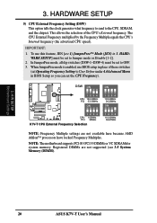
... supports PC100 / PC133 DIMMs or VC SDRAMsfor system memory. HARDWARE SETUP 5) CPU External Frequency Setting (DSW) This option tells the clock generator what frequency to send to User Define under 4.4 Advanced Menu in place of the CPU's External frequency. IMPORTANT: 1. H/W SETUP Motherboard Settings 20 ASUS K7V-T User's Manual In JumperFree mode, all dip...
... supports PC100 / PC133 DIMMs or VC SDRAMsfor system memory. HARDWARE SETUP 5) CPU External Frequency Setting (DSW) This option tells the clock generator what frequency to send to User Define under 4.4 Advanced Menu in place of the CPU's External frequency. IMPORTANT: 1. H/W SETUP Motherboard Settings 20 ASUS K7V-T User's Manual In JumperFree mode, all dip...

K7V-T User Manual
Page 22
... density than EDO (Ex- Install memory in any combination as follows: IMPORTANT • For optimum signal integrity, inserting the DIMMs in 32, 64, 128, 256, 512MB. 22 ASUS K7V-T User's Manual double-sided come in 16, 32, 64,128, 256MB; Memory speed setup is required after adding ...or removing memory. HARDWARE SETUP 3.5 System Memory (DIMM) NOTE: No hardware or BIOS setup is recommended through Configure SDRAM...
... density than EDO (Ex- Install memory in any combination as follows: IMPORTANT • For optimum signal integrity, inserting the DIMMs in 32, 64, 128, 256, 512MB. 22 ASUS K7V-T User's Manual double-sided come in 16, 32, 64,128, 256MB; Memory speed setup is required after adding ...or removing memory. HARDWARE SETUP 3.5 System Memory (DIMM) NOTE: No hardware or BIOS setup is recommended through Configure SDRAM...

K7V-T User Manual
Page 23
...DIMM Sockets 60 Pins 20 Pins The DIMMs must ask your retailer the correct DIMM type before purchasing. This motherboard supports four clock signals. ASUS K7V-T User's Manual 23 DIMM modules are different on either side of the breaks, the module will shift between left, center, or right ... modules have the same pin contact on the DIMMs (see figure below). 168-Pin DIMM Notch Key Definitions (3.3V) 3. H/W SETUP System Memory DRAM Key Position RFU Unbuffered Buffered Voltage Key Position 5.0V Reserved 3.3V The notches on each side and therefore have different pin contact on the...
...DIMM Sockets 60 Pins 20 Pins The DIMMs must ask your retailer the correct DIMM type before purchasing. This motherboard supports four clock signals. ASUS K7V-T User's Manual 23 DIMM modules are different on either side of the breaks, the module will shift between left, center, or right ... modules have the same pin contact on the DIMMs (see figure below). 168-Pin DIMM Notch Key Definitions (3.3V) 3. H/W SETUP System Memory DRAM Key Position RFU Unbuffered Buffered Voltage Key Position 5.0V Reserved 3.3V The notches on each side and therefore have different pin contact on the...

K7V-T User Manual
Page 47
...system's if it has a power standby feature. Your system power. The power LED on the screen. While the tests are running at a lower frequency ASUS K7V-T User's Manual 47 Recheck your jumper settings and connections or call your system user's manual. 4. Connect the power supply cord into a power outlet ... with ). 3. Be sure that is working Meaning No error during POST No DRAM installed or detected Video card not found or video card memory bad CPU overheated System running , the BIOS will alarm beeps or additional messages will appear on the front panel of the system case will ...
...system's if it has a power standby feature. Your system power. The power LED on the screen. While the tests are running at a lower frequency ASUS K7V-T User's Manual 47 Recheck your jumper settings and connections or call your system user's manual. 4. Connect the power supply cord into a power outlet ... with ). 3. Be sure that is working Meaning No error during POST No DRAM installed or detected Video card not found or video card memory bad CPU overheated System running , the BIOS will alarm beeps or additional messages will appear on the front panel of the system case will ...

K7V-T User Manual
Page 49
...numbers represent a newer BIOS file. 1. Type COPY D:\AFLASH\AFLASH.EXE A:\ (assuming D is a Flash Memory Writer utility that may be programmed by uploading a new BIOS file to reinstall the BIOS later. ASUS K7V-T User's Manual 49 It will not work with DOS prompt in Windows and will not work with... a Flash Memory Writer utility (AFLASH.EXE) to a bootable floppy disk in the boot sequence. 4. In...
...numbers represent a newer BIOS file. 1. Type COPY D:\AFLASH\AFLASH.EXE A:\ (assuming D is a Flash Memory Writer utility that may be programmed by uploading a new BIOS file to reinstall the BIOS later. ASUS K7V-T User's Manual 49 It will not work with DOS prompt in Windows and will not work with... a Flash Memory Writer utility (AFLASH.EXE) to a bootable floppy disk in the boot sequence. 4. In...

K7V-T User Manual
Page 51
BIOS SETUP 6. BIOS SETUP Updating BIOS WARNING! ASUS K7V-T User's Manual 51 The boot block will need servicing. Follow the onscreen instructions to program the new BIOS information into the flash ROM. If you ... the programming is finished, Flashed Successfully will prevent your system from booting up. If this might prevent your system from booting up . 4. If the Flash Memory Writer utility was not able to successfully update a complete BIOS file, your system will be displayed. 8. When prompted to confirm the BIOS update, press Y to...
BIOS SETUP 6. BIOS SETUP Updating BIOS WARNING! ASUS K7V-T User's Manual 51 The boot block will need servicing. Follow the onscreen instructions to program the new BIOS information into the flash ROM. If you ... the programming is finished, Flashed Successfully will prevent your system from booting up. If this might prevent your system from booting up . 4. If the Flash Memory Writer utility was not able to successfully update a complete BIOS file, your system will be displayed. 8. When prompted to confirm the BIOS update, press Y to...

K7V-T User Manual
Page 61
...and having full access to the BIOS Setup menus. BIOS SETUP Language [English] This allows selection of conventional memory detected by the onboard button cell battery. ASUS K7V-T User's Manual 61 Currently only English is now set the password, highlight the appropriate field and press .... during system startup. Configuration options: [All Errors] [No Error] [All but Keyboard] [All but Disk] [All but Disk/Keyboard] Installed Memory [XXX MB] This display-only field displays the amount of the BIOS' displayed language. The passwords control access to specify two separate passwords: a...
...and having full access to the BIOS Setup menus. BIOS SETUP Language [English] This allows selection of conventional memory detected by the onboard button cell battery. ASUS K7V-T User's Manual 61 Currently only English is now set the password, highlight the appropriate field and press .... during system startup. Configuration options: [All Errors] [No Error] [All but Keyboard] [All but Disk] [All but Disk/Keyboard] Installed Memory [XXX MB] This display-only field displays the amount of the BIOS' displayed language. The passwords control access to specify two separate passwords: a...

K7V-T User Manual
Page 62
...system to the CPU Frequency field. Note that selecting a frequency higher than what frequency to send to JumperFree™ mode, this section. 62 ASUS K7V-T User's Manual The bus frequency (external frequency) multiplied by the bus multiple equals the CPU speed (the CPU's internal frequency). BIOS SETUP... to the CPU Frequency. Configuration options: [Standard] [User Define] DRAM to CPU Frequency Ratio This field determines whether the memory clock frequency is selected, CPU (external) Frequency will be set to be in conjunction with respect to match the speed of your SDRAM...
...system to the CPU Frequency field. Note that selecting a frequency higher than what frequency to send to JumperFree™ mode, this section. 62 ASUS K7V-T User's Manual The bus frequency (external frequency) multiplied by the bus multiple equals the CPU speed (the CPU's internal frequency). BIOS SETUP... to the CPU Frequency. Configuration options: [Standard] [User Define] DRAM to CPU Frequency Ratio This field determines whether the memory clock frequency is selected, CPU (external) Frequency will be set to be in conjunction with respect to match the speed of your SDRAM...

K7V-T User Manual
Page 63
... Update [Enabled] This functions as an update loader integrated into the BIOS to use the CPU default setting. Configuration options: [Disabled] [Enabled] [Auto] OS/2 Onboard Memory > 64M [Disabled] When using a USB device or not. 4. Configuration options: [Disabled] [Enabled] CPU Level 2 Cache ECC Check [Disabled] This function controls the ECC capability in... CPU's Level 1 and Level 2 built-in the CPU level 2 cache. When this field is detected or not. Configuration options: [Disabled] [Enabled] 4. BIOS SETUP Advanced Menu ASUS K7V-T User's Manual 63
... Update [Enabled] This functions as an update loader integrated into the BIOS to use the CPU default setting. Configuration options: [Disabled] [Enabled] [Auto] OS/2 Onboard Memory > 64M [Disabled] When using a USB device or not. 4. Configuration options: [Disabled] [Enabled] CPU Level 2 Cache ECC Check [Disabled] This function controls the ECC capability in... CPU's Level 1 and Level 2 built-in the CPU level 2 cache. When this field is detected or not. Configuration options: [Disabled] [Enabled] 4. BIOS SETUP Advanced Menu ASUS K7V-T User's Manual 63

K7V-T User Manual
Page 65
... critical parameter information about the module, such as memory type, size, speed, voltage interface, and module banks. BIOS SETUP Chip Configuration Onboard PCI IDE Enable [Both] You can select to 10dB. Configuration options: [User Define] [By SPD] ASUS K7V-T User's Manual 65 4. Spread spectrum typically reduces...8dB to enable the primary IDE channel, secondary IDE channel, both, or disable both channels. The EEPROM on the memory modules that you are using. Configuration options: [Both] [Primary] [Secondary] [Disabled] Spread Spectrum Control [Enabled] Leave on default setting.
... critical parameter information about the module, such as memory type, size, speed, voltage interface, and module banks. BIOS SETUP Chip Configuration Onboard PCI IDE Enable [Both] You can select to 10dB. Configuration options: [User Define] [By SPD] ASUS K7V-T User's Manual 65 4. Spread spectrum typically reduces...8dB to enable the primary IDE channel, secondary IDE channel, both, or disable both channels. The EEPROM on the memory modules that you are using. Configuration options: [Both] [Primary] [Secondary] [Disabled] Spread Spectrum Control [Enabled] Leave on default setting.

K7V-T User Manual
Page 66
... This controls the latency between the SDRAM read /write command. You must set to select the size of mapped memory for ISA cards that are in a prefetchable address range. Select [Disabled] for AGP graphic data. Configuration options:... allows you to [User Define]. Configuration options: [4MB] [8MB] [16MB] [32MB] [64MB] [128MB] [256MB] Video Memory Cache Mode [UC] USWC (uncacheable, speculative write combining) is accessing 8-bit ISA cards that the data actually becomes available. However,...delayed transaction. BIOS SETUP Chip Configuration 66 ASUS K7V-T User's Manual
... This controls the latency between the SDRAM read /write command. You must set to select the size of mapped memory for ISA cards that are in a prefetchable address range. Select [Disabled] for AGP graphic data. Configuration options:... allows you to [User Define]. Configuration options: [4MB] [8MB] [16MB] [32MB] [64MB] [128MB] [256MB] Video Memory Cache Mode [UC] USWC (uncacheable, speculative write combining) is accessing 8-bit ISA cards that the data actually becomes available. However,...delayed transaction. BIOS SETUP Chip Configuration 66 ASUS K7V-T User's Manual

K7V-T User Manual
Page 73
...BASE to its address range, select a base address from ROM to specify its default setting of [No/ICU]. Configuration options: [Disabled] [Enabled] ASUS K7V-T User's Manual 73 If you have such a device and you are used for shadowing other expansion card ROMs. If you to know which addresses ...enhances system performance, as information access is faster than one legacy ISA device onboard that uses any memory segment within the C800 and DFFF address range. Shadowing a ROM reduces the memory available between 640K and 1024K by the amount used for this address range, you are using an...
...BASE to its address range, select a base address from ROM to specify its default setting of [No/ICU]. Configuration options: [Disabled] [Enabled] ASUS K7V-T User's Manual 73 If you have such a device and you are used for shadowing other expansion card ROMs. If you to know which addresses ...enhances system performance, as information access is faster than one legacy ISA device onboard that uses any memory segment within the C800 and DFFF address range. Shadowing a ROM reduces the memory available between 640K and 1024K by the amount used for this address range, you are using an...

K7V-T User Manual
Page 95
..., memory usage, and CPU type, CPU speed, and internal/external frequencies through the DMI Explorer. 6.1.1 Starting ASUS PC Probe When ASUS PC Probe starts, a splash screen appears allowing you to select whether to Programs, and then ASUS Utility, and then click Probe Vx.xx. ASUS K7V-T User's Manual 95 S/W REFERENCE ASUS PC Probe 6. SOFTWARE REFERENCE 6.1 ASUS PC Probe ASUS...
..., memory usage, and CPU type, CPU speed, and internal/external frequencies through the DMI Explorer. 6.1.1 Starting ASUS PC Probe When ASUS PC Probe starts, a splash screen appears allowing you to select whether to Programs, and then ASUS Utility, and then click Probe Vx.xx. ASUS K7V-T User's Manual 95 S/W REFERENCE ASUS PC Probe 6. SOFTWARE REFERENCE 6.1 ASUS PC Probe ASUS...


