K7M User Manual
Page 7
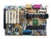
... that at least 20 amperes on the +5-volt lead and 10mA on the +5-volt standby lead (+5VSB) (see 19) ATX Power Suppy Connector in powering up if your package is divided into the following sections: 1) INTRODUCTION Manual information and checklist ...and specifications 3) HARDWARE SETUP Instructions on setting up the motherboard 4) BIOS SETUP Instructions on setting up the BIOS software 5) SOFTWARE SETUP Instructions on setting up the included software 6) SOFTWARE REFERENCE Reference material for this motherboard. 1. ASUS K7M User's Manual 7 INTRODUCTION 1.1 How This Manual Is...
... that at least 20 amperes on the +5-volt lead and 10mA on the +5-volt standby lead (+5VSB) (see 19) ATX Power Suppy Connector in powering up if your package is divided into the following sections: 1) INTRODUCTION Manual information and checklist ...and specifications 3) HARDWARE SETUP Instructions on setting up the motherboard 4) BIOS SETUP Instructions on setting up the BIOS software 5) SOFTWARE SETUP Instructions on setting up the included software 6) SOFTWARE REFERENCE Reference material for this motherboard. 1. ASUS K7M User's Manual 7 INTRODUCTION 1.1 How This Manual Is...
K7M User Manual
Page 8
FEATURES 2.1 The ASUS K7M Motherboard The ASUS K7M motherboard is optimized to deliver enhanced AMD Athlon™ processor system performance. • South Bridge System Chipset: VIA VT82C686A PCIset with PCI Super I/O integrated peripheral controller ... an Accelerated Graphics Port card for high performance component level interconnect targeted at 3D graphical display applications using a 1X or 2X mode bus. • USB: Supports up to 4 USB ports, two on the back panel and two midboard (optional), for virtually automatic setup. • PC100 Memory Support: Equipped with three DIMM sockets...
FEATURES 2.1 The ASUS K7M Motherboard The ASUS K7M motherboard is optimized to deliver enhanced AMD Athlon™ processor system performance. • South Bridge System Chipset: VIA VT82C686A PCIset with PCI Super I/O integrated peripheral controller ... an Accelerated Graphics Port card for high performance component level interconnect targeted at 3D graphical display applications using a 1X or 2X mode bus. • USB: Supports up to 4 USB ports, two on the back panel and two midboard (optional), for virtually automatic setup. • PC100 Memory Support: Equipped with three DIMM sockets...

K7M User Manual
Page 9
... compliant, Analog Device's 3D sound circuitry, sample rate conversion from 7kHz to meet PC 99 compliancy, major connectors in this motherboard are color-coded. 2.1.1.1 Optional Components The following onboard components are supported midboard. 2. FEATURES • UltraDMA/66 & UltraDMA/33...ASUS PC Probe. • Additional USB Ports: For more control and protection over the motherboard. Provides CPU/SDRAM frequency adjustments, and HD/SCSI/ZIP/CD/Floppy/Network boot selection. • Color-coded Connectors: To enhance user accessibility to system components and to 48kHz. ASUS K7M...
... compliant, Analog Device's 3D sound circuitry, sample rate conversion from 7kHz to meet PC 99 compliancy, major connectors in this motherboard are color-coded. 2.1.1.1 Optional Components The following onboard components are supported midboard. 2. FEATURES • UltraDMA/66 & UltraDMA/33...ASUS PC Probe. • Additional USB Ports: For more control and protection over the motherboard. Provides CPU/SDRAM frequency adjustments, and HD/SCSI/ZIP/CD/Floppy/Network boot selection. • Color-coded Connectors: To enhance user accessibility to system components and to 48kHz. ASUS K7M...
K7M User Manual
Page 12
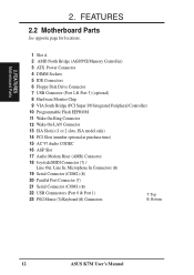
FEATURES Motherboard Parts 2. 2. FEATURES 2.2 Motherboard Parts See opposite page for locations. 1 Slot A 2 AMD North Bridge (AGP/PCI/Memory Controller) 3 ATX Power Connector 4 DIMM Sockets 5 IDE Connectors 6 Floppy Disk Drive Connector 7 USB Connector (Port 2 & Port 3) (optional) 8 Hardware Monitor Chip 9 VIA South Bridge (PCI Super...Microphone In Connectors (B) 19 Serial Connector (COM2) (B) 20 Parallel Port Connector (T) 21 Serial Connector (COM1) (B) 22 USB Connnectors (Port 0 & Port 1) 23 PS/2 Mouse (T)/Keyboard (B) Connectors T: Top B: Bottom 12 ASUS K7M User's Manual
FEATURES Motherboard Parts 2. 2. FEATURES 2.2 Motherboard Parts See opposite page for locations. 1 Slot A 2 AMD North Bridge (AGP/PCI/Memory Controller) 3 ATX Power Connector 4 DIMM Sockets 5 IDE Connectors 6 Floppy Disk Drive Connector 7 USB Connector (Port 2 & Port 3) (optional) 8 Hardware Monitor Chip 9 VIA South Bridge (PCI Super...Microphone In Connectors (B) 19 Serial Connector (COM2) (B) 20 Parallel Port Connector (T) 21 Serial Connector (COM1) (B) 22 USB Connnectors (Port 0 & Port 1) 23 PS/2 Mouse (T)/Keyboard (B) Connectors T: Top B: Bottom 12 ASUS K7M User's Manual
K7M User Manual
Page 14
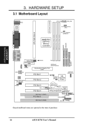
...Motherboard Layout 3. HARDWARE SETUP 3.1 Motherboard Layout PARALLEL PORT ATX Power Connector DIMM3 (64/72 bit, 168-pin module) DIMM2 (64/72 bit, 168-pin module) DIMM1 (64/72 bit, 168-pin module) PRIMARY IDE SECONDARY IDE T: Mouse PS/2 B: Keyboard USB...Audio Codec Audio Codec Setting (SPK, AUD_EN1, AUD_EN2, ADN#) HPHONE PCI Slot 1 PCI Slot 2 K7M PS/2 Mouse VIA Selection VT82C686A (MSDATA) PCIset USBPORT (Ports 2 & 3) PCI Slot 3 WOL_CON...Cell CMOS Power WOR CLRTC (R181) 2Mbit Flash EEPROM (Programmable BIOS) ASUS ASIC Hardware Monitor CHA_FAN CHASSIS IR SMB ISA Slot 2 (ISA2) IDE ...
...Motherboard Layout 3. HARDWARE SETUP 3.1 Motherboard Layout PARALLEL PORT ATX Power Connector DIMM3 (64/72 bit, 168-pin module) DIMM2 (64/72 bit, 168-pin module) DIMM1 (64/72 bit, 168-pin module) PRIMARY IDE SECONDARY IDE T: Mouse PS/2 B: Keyboard USB...Audio Codec Audio Codec Setting (SPK, AUD_EN1, AUD_EN2, ADN#) HPHONE PCI Slot 1 PCI Slot 2 K7M PS/2 Mouse VIA Selection VT82C686A (MSDATA) PCIset USBPORT (Ports 2 & 3) PCI Slot 3 WOL_CON...Cell CMOS Power WOR CLRTC (R181) 2Mbit Flash EEPROM (Programmable BIOS) ASUS ASIC Hardware Monitor CHA_FAN CHASSIS IR SMB ISA Slot 2 (ISA2) IDE ...
K7M User Manual
Page 15
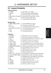
3. H/W SETUP Layout Contents 3. HARDWARE SETUP 3.2 Layout Contents Motherboard Settings 1) 3VSBSLT p.18 Vaux Setting (+3V/+3VSB) 2) MSDATA p.18 PS/2...Riser Slot Connectors 1) PS2KBMS p.34 PS/2 Mouse Connector (6-pin female) 2) PS2KBMS p.34 PS/2 Keyboard Connector (6-pin female) 3) USB p.35 Universal Serial Bus Ports 0 & 1 (Two 4-pin female) 4) PRINTER p.35 Parallel Port Connector (25-pin female) ... p.42 Chassis Intrusion Alarm Lead (4-1 pins) 19) ATXPWR p.42 ATX Power Supply Connector (20 pins) 20) USBPORT p.43 USB Connector Set (10-1 pins) ASUS K7M User's Manual 15
3. H/W SETUP Layout Contents 3. HARDWARE SETUP 3.2 Layout Contents Motherboard Settings 1) 3VSBSLT p.18 Vaux Setting (+3V/+3VSB) 2) MSDATA p.18 PS/2...Riser Slot Connectors 1) PS2KBMS p.34 PS/2 Mouse Connector (6-pin female) 2) PS2KBMS p.34 PS/2 Keyboard Connector (6-pin female) 3) USB p.35 Universal Serial Bus Ports 0 & 1 (Two 4-pin female) 4) PRINTER p.35 Parallel Port Connector (25-pin female) ... p.42 Chassis Intrusion Alarm Lead (4-1 pins) 19) ATXPWR p.42 ATX Power Supply Connector (20 pins) 20) USBPORT p.43 USB Connector Set (10-1 pins) ASUS K7M User's Manual 15

K7M User Manual
Page 31
... your expansion card. 3.7.2 Assigning IRQs for possible future use . ASUS K7M User's Manual 31 Unplug your computer system's cover and the bracket plate on the slot with the screw you intend to both your motherboard and expansion cards. 3.7.1 Expansion Card Installation Procedure 1. Failure to ... the necessary software drivers for your expansion card and make the system unstable or cards inoperable. PCI slot 5 shared AGP slot shared Onboard USB controller - Conflicts will arise between the two PCI groups that the cards do so may cause severe damage to use . 3. 3. H/W...
... your expansion card. 3.7.2 Assigning IRQs for possible future use . ASUS K7M User's Manual 31 Unplug your computer system's cover and the bracket plate on the slot with the screw you intend to both your motherboard and expansion cards. 3.7.1 Expansion Card Installation Procedure 1. Failure to ... the necessary software drivers for your expansion card and make the system unstable or cards inoperable. PCI slot 5 shared AGP slot shared Onboard USB controller - Conflicts will arise between the two PCI groups that the cards do so may cause severe damage to use . 3. 3. H/W...

K7M User Manual
Page 35
... a serial port bracket connected from the motherboard to the serial port. 3. HARDWARE SETUP 3) Universal Serial BUS Ports 1 & 2 (Black two 4-pin USB) Two USB ports are available for a mouse or other serial devices. H/W SETUP D CMoAnCnhecatnonrsels COM 1 COM 2 Serial Ports (9-pin Male) ASUS K7M User's Manual 35 USB 1 Universal Serial Bus (USB) 2 4) Parallel Port Connector (Burgundy ... Onboard Serial Port 1 in 4.2.2 I /O Device Configuration). NOTE: Serial printers must be connected to an expansion slot opening. A second serial port is ready for connecting USB devices.
... a serial port bracket connected from the motherboard to the serial port. 3. HARDWARE SETUP 3) Universal Serial BUS Ports 1 & 2 (Black two 4-pin USB) Two USB ports are available for a mouse or other serial devices. H/W SETUP D CMoAnCnhecatnonrsels COM 1 COM 2 Serial Ports (9-pin Male) ASUS K7M User's Manual 35 USB 1 Universal Serial Bus (USB) 2 4) Parallel Port Connector (Burgundy ... Onboard Serial Port 1 in 4.2.2 I /O Device Configuration). NOTE: Serial printers must be connected to an expansion slot opening. A second serial port is ready for connecting USB devices.

K7M User Manual
Page 43
... Panel Connectors ASUS K7M User's Manual 43 H/W SETUP Connectors 3. Keyboard Lock Speaker Power LED Connector +5 V PLED Keylock Ground +5V Ground Ground Speaker ExtSMI# Ground PWR +3VSB Reset Ground K7M SMI Lead Reset SW ATX Power Switch* * Requires an ATX power supply. If ...back panels are inadequate, a USB connector set . HARDWARE SETUP 20) USB Connector Set (10-1 pin USBPORT) If the USB Ports on your computer's chassis. 01 01 01 01 01 01 K7M K7M USB Ports 2 and 3 Optional USB USBPORT 61 6: USB Power 7: USBP3- 8: USBP3+ 9: GND 10 5 1: USB Power 2: USBP2- 3: USBP2...
... Panel Connectors ASUS K7M User's Manual 43 H/W SETUP Connectors 3. Keyboard Lock Speaker Power LED Connector +5 V PLED Keylock Ground +5V Ground Ground Speaker ExtSMI# Ground PWR +3VSB Reset Ground K7M SMI Lead Reset SW ATX Power Switch* * Requires an ATX power supply. If ...back panels are inadequate, a USB connector set . HARDWARE SETUP 20) USB Connector Set (10-1 pin USBPORT) If the USB Ports on your computer's chassis. 01 01 01 01 01 01 K7M K7M USB Ports 2 and 3 Optional USB USBPORT 61 6: USB Power 7: USBP3- 8: USBP3+ 9: GND 10 5 1: USB Power 2: USBP2- 3: USBP2...

K7M User Manual
Page 60
...Enabled] Leave on the default setting [Disabled] if you are using any USB legacy devices. ClkGen for empty PCI slots and DIMM sockets. Available options: [Disabled] [USB Port 0&1] [USB Port 2&3] [All USB Port] USB KB/Mouse Legacy Support [Disabled] Leave on default setting. 4. Spread ...bit ISA cards that are not using a monochrome display adapter (MDA). USB Controller [All USB Port] This motherboard supports Universal Serial Bus (USB) devices. You may choose to 10dB. BIOS SETUP Advanced Chipset 60 ASUS K7M User's Manual BIOS SETUP MDA Support [No] Leave on default settings. ...
...Enabled] Leave on the default setting [Disabled] if you are using any USB legacy devices. ClkGen for empty PCI slots and DIMM sockets. Available options: [Disabled] [USB Port 0&1] [USB Port 2&3] [All USB Port] USB KB/Mouse Legacy Support [Disabled] Leave on default setting. 4. Spread ...bit ISA cards that are not using a monochrome display adapter (MDA). USB Controller [All USB Port] This motherboard supports Universal Serial Bus (USB) devices. You may choose to 10dB. BIOS SETUP Advanced Chipset 60 ASUS K7M User's Manual BIOS SETUP MDA Support [No] Leave on default settings. ...


