K7M User Manual
Page 7
...) (see 19) ATX Power Suppy Connector in 3.8 External Connectors). If you discover damaged or missing items, please contact your retailer. 1.2.1 Motherboard (1) ASUS Motherboard (1) Universal Retention Mechanism (factory installed) (1) ASUS USB Connector Set (1)... Ribbon cable for master and slave UltraDMA/33 & UltraDMA/66 IDE drives (1) Ribbon cable for the included software 7) APPENDIX Optional items and general reference 1.2 Item Checklist Check that at least 20 amperes on the +5-volt lead and 10mA on setting up if your package is inadequate. ASUS K7M...
...) (see 19) ATX Power Suppy Connector in 3.8 External Connectors). If you discover damaged or missing items, please contact your retailer. 1.2.1 Motherboard (1) ASUS Motherboard (1) Universal Retention Mechanism (factory installed) (1) ASUS USB Connector Set (1)... Ribbon cable for master and slave UltraDMA/33 & UltraDMA/66 IDE drives (1) Ribbon cable for the included software 7) APPENDIX Optional items and general reference 1.2 Item Checklist Check that at least 20 amperes on the +5-volt lead and 10mA on setting up if your package is inadequate. ASUS K7M...
K7M User Manual
Page 12
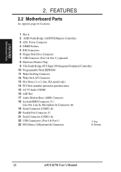
2. FEATURES Motherboard Parts 2. FEATURES 2.2 Motherboard Parts See opposite page for locations. 1 Slot A 2 AMD North Bridge (AGP/PCI/Memory Controller) 3 ATX Power Connector 4 DIMM Sockets 5 IDE Connectors 6 Floppy Disk Drive Connector 7 USB Connector (Port 2 & Port 3) (optional) 8 Hardware Monitor Chip 9 VIA South Bridge (PCI Super I/O Integrated Peripheral... 19 Serial Connector (COM2) (B) 20 Parallel Port Connector (T) 21 Serial Connector (COM1) (B) 22 USB Connnectors (Port 0 & Port 1) 23 PS/2 Mouse (T)/Keyboard (B) Connectors T: Top B: Bottom 12 ASUS K7M User's Manual
2. FEATURES Motherboard Parts 2. FEATURES 2.2 Motherboard Parts See opposite page for locations. 1 Slot A 2 AMD North Bridge (AGP/PCI/Memory Controller) 3 ATX Power Connector 4 DIMM Sockets 5 IDE Connectors 6 Floppy Disk Drive Connector 7 USB Connector (Port 2 & Port 3) (optional) 8 Hardware Monitor Chip 9 VIA South Bridge (PCI Super I/O Integrated Peripheral... 19 Serial Connector (COM2) (B) 20 Parallel Port Connector (T) 21 Serial Connector (COM1) (B) 22 USB Connnectors (Port 0 & Port 1) 23 PS/2 Mouse (T)/Keyboard (B) Connectors T: Top B: Bottom 12 ASUS K7M User's Manual
K7M User Manual
Page 14
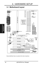
H/W SETUP Motherboard Layout 3. HARDWARE SETUP 3.1 Motherboard Layout PARALLEL PORT ATX Power Connector DIMM3 (64/72 bit, ...Graphic Port (AGP) VIDEO AUX Audio Codec Audio Codec Setting (SPK, AUD_EN1, AUD_EN2, ADN#) HPHONE PCI Slot 1 PCI Slot 2 K7M PS/2 Mouse VIA Selection VT82C686A (MSDATA) PCIset USBPORT (Ports 2 & 3) PCI Slot 3 WOL_CON PCI Slot 4 ISA Slot 1 (... PCI Slot 5 CR2032 3V Lithium Cell CMOS Power WOR CLRTC (R181) 2Mbit Flash EEPROM (Programmable BIOS) ASUS ASIC Hardware Monitor CHA_FAN CHASSIS IR SMB ISA Slot 2 (ISA2) IDE LED PANEL Grayed midboard items are optional ...
H/W SETUP Motherboard Layout 3. HARDWARE SETUP 3.1 Motherboard Layout PARALLEL PORT ATX Power Connector DIMM3 (64/72 bit, ...Graphic Port (AGP) VIDEO AUX Audio Codec Audio Codec Setting (SPK, AUD_EN1, AUD_EN2, ADN#) HPHONE PCI Slot 1 PCI Slot 2 K7M PS/2 Mouse VIA Selection VT82C686A (MSDATA) PCIset USBPORT (Ports 2 & 3) PCI Slot 3 WOL_CON PCI Slot 4 ISA Slot 1 (... PCI Slot 5 CR2032 3V Lithium Cell CMOS Power WOR CLRTC (R181) 2Mbit Flash EEPROM (Programmable BIOS) ASUS ASIC Hardware Monitor CHA_FAN CHASSIS IR SMB ISA Slot 2 (ISA2) IDE LED PANEL Grayed midboard items are optional ...
K7M User Manual
Page 15
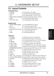
HARDWARE SETUP 3.2 Layout Contents Motherboard Settings 1) 3VSBSLT p.18 Vaux Setting (+3V/+3VSB) 2) MSDATA p.18 PS/2 Mouse Setting (IRQ12/MSDATA) 3) VIO p.19 I/O Voltage Setting (3.31V/3.4V/3.56V) 4) SPK/AUD_EN1/_EN2/ADN# p....) 16) IR p.41 Serial Infrared Module Connector (5 pins) 17) SMB p.41 SMBus Connector (5-1 pins) 18) CHASSIS p.42 Chassis Intrusion Alarm Lead (4-1 pins) 19) ATXPWR p.42 ATX Power Supply Connector (20 pins) 20) USBPORT p.43 USB Connector Set (10-1 pins) ASUS K7M User's Manual 15 H/W SETUP Layout Contents 3. 3.
HARDWARE SETUP 3.2 Layout Contents Motherboard Settings 1) 3VSBSLT p.18 Vaux Setting (+3V/+3VSB) 2) MSDATA p.18 PS/2 Mouse Setting (IRQ12/MSDATA) 3) VIO p.19 I/O Voltage Setting (3.31V/3.4V/3.56V) 4) SPK/AUD_EN1/_EN2/ADN# p....) 16) IR p.41 Serial Infrared Module Connector (5 pins) 17) SMB p.41 SMBus Connector (5-1 pins) 18) CHASSIS p.42 Chassis Intrusion Alarm Lead (4-1 pins) 19) ATXPWR p.42 ATX Power Supply Connector (20 pins) 20) USBPORT p.43 USB Connector Set (10-1 pins) ASUS K7M User's Manual 15 H/W SETUP Layout Contents 3. 3.

K7M User Manual
Page 16
H/W SETUP Layout Contents 16 ASUS K7M User's Manual 3. HARDWARE SETUP 21) SPEAKER (PANEL) 22) PWRLED (PANEL) 23) RESET (PANEL) 24) PWRSW (PANEL) 25) SMI (PANEL) p.44 System Warning Speaker Connector (4 pins) p.44 System Power LED Lead (3-1 pins) p.44 Reset Switch Lead (2 pins) p.44 ATX Power / Soft-Off Switch Lead (2 pins) p.44 System Management Interrupt Switch Lead (2 pins) 3.
H/W SETUP Layout Contents 16 ASUS K7M User's Manual 3. HARDWARE SETUP 21) SPEAKER (PANEL) 22) PWRLED (PANEL) 23) RESET (PANEL) 24) PWRSW (PANEL) 25) SMI (PANEL) p.44 System Warning Speaker Connector (4 pins) p.44 System Power LED Lead (3-1 pins) p.44 Reset Switch Lead (2 pins) p.44 ATX Power / Soft-Off Switch Lead (2 pins) p.44 System Management Interrupt Switch Lead (2 pins) 3.
K7M User Manual
Page 17
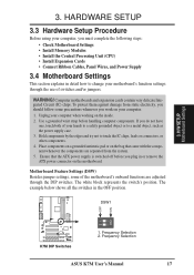
...motherboard. Frequency Selection ASUS K7M User's Manual 17 WARNING! Hold components by the edges and try not to a metal object, such as the power supply case. 3. The white block represents the switch's position. DSW1 01 01 01 ON 12 K7M K7M DIP Switches 1. Use a grounded wrist strap before you plug in or remove the ATX... power connector on the bag that the ATX power supply is switched off before handling computer components. Ensure ...
...motherboard. Frequency Selection ASUS K7M User's Manual 17 WARNING! Hold components by the edges and try not to a metal object, such as the power supply case. 3. The white block represents the switch's position. DSW1 01 01 01 ON 12 K7M K7M DIP Switches 1. Use a grounded wrist strap before you plug in or remove the ATX... power connector on the bag that the ATX power supply is switched off before handling computer components. Ensure ...

K7M User Manual
Page 38
... This feature requires that Wake-On-Ring features are enabled (see 4.4.3 Power Management) and that your system has an ATX power supply with at least 720mA +5 volt standby power K7M K7M Wake-On-LAN Connector Ground PME +5 Volt Standby WOL_CON 11) Wake-On-Ring Connector (2-pin WOR) This connector connects ...HARDWARE SETUP 10) Wake-On-LAN Connector (3-pin WOL_CON) This connector connects to a LAN card with a Wake-On-LAN output, such as the ASUS PCI-L101 Ethernet card (see 4.4.3 Power Management) and that Wake-On-Lan features are enabled (see 7. NOTE: For external modems, Wake-On-Ring...
... This feature requires that Wake-On-Ring features are enabled (see 4.4.3 Power Management) and that your system has an ATX power supply with at least 720mA +5 volt standby power K7M K7M Wake-On-LAN Connector Ground PME +5 Volt Standby WOL_CON 11) Wake-On-Ring Connector (2-pin WOR) This connector connects ...HARDWARE SETUP 10) Wake-On-LAN Connector (3-pin WOL_CON) This connector connects to a LAN card with a Wake-On-LAN output, such as the ASUS PCI-L101 Ethernet card (see 4.4.3 Power Management) and that Wake-On-Lan features are enabled (see 7. NOTE: For external modems, Wake-On-Ring...

K7M User Manual
Page 40
3. HP OUT LT GND HP OUT RT K7M K7M True-Level Line Out Header 1 HPHONE 40 ASUS K7M User's Manual H/W SETUP Connectors 01 01 01 01 01 01 3. It also allows the sharing of having to the motherboard instead of mono_in (such as a phone) and mono_out (such as a CD-ROM, TV tuner, or... MPEG card. HARDWARE SETUP 14) Internal Audio Connectors (4-pin CD, AUX, VIDEO, MODEM) These connectors allow you to connect a chassis mounted headphone to attach an external headphone onto the ATX connectors....
3. HP OUT LT GND HP OUT RT K7M K7M True-Level Line Out Header 1 HPHONE 40 ASUS K7M User's Manual H/W SETUP Connectors 01 01 01 01 01 01 3. It also allows the sharing of having to the motherboard instead of mono_in (such as a phone) and mono_out (such as a CD-ROM, TV tuner, or... MPEG card. HARDWARE SETUP 14) Internal Audio Connectors (4-pin CD, AUX, VIDEO, MODEM) These connectors allow you to connect a chassis mounted headphone to attach an external headphone onto the ATX connectors....

K7M User Manual
Page 42
...0Volts +3.3 Volts Ground Ground Power Supply On Ground +5.0 Volts Ground Ground +5.0 Volts Ground Ground K7M -5.0 Volts Power Good +5.0 Volts +5V Standby +5.0 Volts +12.0Volts K7M ATX Power Connector 42 ASUS K7M User's Manual The plug from the chassis to connect to prevent unnecessary power loss. +5Volt...any chassis component is removed, the contact should be installed to an ATX power supply. Two wires should open and the motherboard will only insert in powering up if your ATX power supply (minimum recommended wattage: 200 watts; 235W for chassis intrusion ...
...0Volts +3.3 Volts Ground Ground Power Supply On Ground +5.0 Volts Ground Ground +5.0 Volts Ground Ground K7M -5.0 Volts Power Good +5.0 Volts +5V Standby +5.0 Volts +12.0Volts K7M ATX Power Connector 42 ASUS K7M User's Manual The plug from the chassis to connect to prevent unnecessary power loss. +5Volt...any chassis component is removed, the contact should be installed to an ATX power supply. Two wires should open and the motherboard will only insert in powering up if your ATX power supply (minimum recommended wattage: 200 watts; 235W for chassis intrusion ...

K7M User Manual
Page 43
...K7M SMI Lead Reset SW ATX Power Switch* * Requires an ATX power supply. The external connector set connects to the 10-1 pin block and mounts to use this connector, you want to use the bundled external connector set is used for items 21-25 (next page). H/W SETUP Connectors 3. K7M System Panel Connectors ASUS K7M... User's Manual 43 3. HARDWARE SETUP 20) USB Connector Set (10-1 pin USBPORT) If the USB Ports on your computer's chassis. 01 01 01 01 01 01 K7M K7M USB Ports 2 and 3 Optional USB ...
...K7M SMI Lead Reset SW ATX Power Switch* * Requires an ATX power supply. The external connector set connects to the 10-1 pin block and mounts to use this connector, you want to use the bundled external connector set is used for items 21-25 (next page). H/W SETUP Connectors 3. K7M System Panel Connectors ASUS K7M... User's Manual 43 3. HARDWARE SETUP 20) USB Connector Set (10-1 pin USBPORT) If the USB Ports on your computer's chassis. 01 01 01 01 01 01 K7M K7M USB Ports 2 and 3 Optional USB ...

K7M User Manual
Page 44
Only SPEAKER will allow you to this lead. H/W SETUP Connectors 44 ASUS K7M User's Manual Two sources (LINE_OUT and SPEAKER) will allow wake-up (the SMI lead cannot wake up can be controlled by a momentary switch connected to ... PWRLED) This 3-1 pin connector connects the system power LED, which lights when the system is powered on the position of the system's power supply. 24) ATX Power Switch Lead (2-pin PWRSW) The system power is a preferred method of rebooting to the case-mounted reset switch for rebooting your power switch. Pushing...
Only SPEAKER will allow you to this lead. H/W SETUP Connectors 44 ASUS K7M User's Manual Two sources (LINE_OUT and SPEAKER) will allow wake-up (the SMI lead cannot wake up can be controlled by a momentary switch connected to ... PWRLED) This 3-1 pin connector connects the system power LED, which lights when the system is powered on the position of the system's power supply. 24) ATX Power Switch Lead (2-pin PWRSW) The system power is a preferred method of rebooting to the case-mounted reset switch for rebooting your power switch. Pushing...

K7M User Manual
Page 45
...system's if it complies with "green" standards or if it has a power standby feature. For ATX power supplies, the system LED will not appear when shutting down the computer?. K7M User's Manual 45 HARDWARE SETUP 3.9 Power Connection Procedures 1. If you do not see anything within... Recheck your jumper settings and connections or call your devices in 4. Follow the instructions in the following order: a. H/W SETUP Power Connections 3. For ATX power supplies, you use Windows 95/98, click the Start button, click Shut Down, and then click Shut down with a surge protector. 5....
...system's if it complies with "green" standards or if it has a power standby feature. For ATX power supplies, the system LED will not appear when shutting down the computer?. K7M User's Manual 45 HARDWARE SETUP 3.9 Power Connection Procedures 1. If you do not see anything within... Recheck your jumper settings and connections or call your devices in 4. Follow the instructions in the following order: a. H/W SETUP Power Connections 3. For ATX power supplies, you use Windows 95/98, click the Start button, click Shut Down, and then click Shut down with a surge protector. 5....

K7M User Manual
Page 62
... Thermal [Ignore] The onboard hardware monitor is put to [Monitor]. Power Button Function [On/Off] When set to [On/Off], the ATX switch can be set the period of the STPCLK# signal when the system is activity detected from the specified IRQ channels. The hard disks automatically...duty cycle of the setting, holding the ATX switch for more than 4 seconds will power off button when pressed for less than 4 seconds. [Suspend] allows the button to detect the CPU and motherboard temperatures. In other words, this feature. BIOS SETUP 62 ASUS K7M User's Manual Modem Use IRQ [N/A] ...
... Thermal [Ignore] The onboard hardware monitor is put to [Monitor]. Power Button Function [On/Off] When set to [On/Off], the ATX switch can be set the period of the STPCLK# signal when the system is activity detected from the specified IRQ channels. The hard disks automatically...duty cycle of the setting, holding the ATX switch for more than 4 seconds will power off button when pressed for less than 4 seconds. [Suspend] allows the button to detect the CPU and motherboard temperatures. In other words, this feature. BIOS SETUP 62 ASUS K7M User's Manual Modem Use IRQ [N/A] ...

K7M User Manual
Page 63
Therefore connection cannot be made on while the computer is off -peak hours. Set to [Enabled] to power on. BIOS SETUP Power Management ASUS K7M User's Manual 63 BIOS SETUP Restore on ) when the modem receives a call while the computer is in a month by sending a wake-up your system after ... Alarm Date / Hour / Minute / Second This allows you can remotely upload/download data to have an unattended or automatic power up the computer (turns the ATX power supply on AC/Power Loss [Power Off] This allows you to set whether you to remotely power up your system through your network by...
Therefore connection cannot be made on while the computer is off -peak hours. Set to [Enabled] to power on. BIOS SETUP Power Management ASUS K7M User's Manual 63 BIOS SETUP Restore on ) when the modem receives a call while the computer is in a month by sending a wake-up your system after ... Alarm Date / Hour / Minute / Second This allows you can remotely upload/download data to have an unattended or automatic power up the computer (turns the ATX power supply on AC/Power Loss [Power Off] This allows you to set whether you to remotely power up your system through your network by...

