
User Guide
Page 1
Motherboard H110M-PLUS D3
Motherboard H110M-PLUS D3
User Guide
Page 3
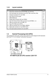
Contents Safety information iv About this guide iv Package contents vi H110M-PLUS D3 specifications summary vi Chapter 1: Product introduction 1.1 Before you proceed 1-1 1.2 Motherboard overview 1-1 1.3 Central Processing Unit (CPU 1-3 1.4 System memory 1-7 1.5 Expansion slots 1-9 1.6 Headers 1-11 1.7 Connectors 1-12 1.8 Software support 1-... 2.4 Main menu 2-14 2.5 Ai Tweaker menu 2-15 2.6 Advanced menu 2-16 2.7 Monitor menu 2-16 2.8 Boot menu 2-17 2.9 Tool menu 2-17 2.10 Exit menu 2-17 Appendices Notices...A-1 ASUS contact information A-4 iii
Contents Safety information iv About this guide iv Package contents vi H110M-PLUS D3 specifications summary vi Chapter 1: Product introduction 1.1 Before you proceed 1-1 1.2 Motherboard overview 1-1 1.3 Central Processing Unit (CPU 1-3 1.4 System memory 1-7 1.5 Expansion slots 1-9 1.6 Headers 1-11 1.7 Connectors 1-12 1.8 Software support 1-... 2.4 Main menu 2-14 2.5 Ai Tweaker menu 2-15 2.6 Advanced menu 2-16 2.7 Monitor menu 2-16 2.8 Boot menu 2-17 2.9 Tool menu 2-17 2.10 Exit menu 2-17 Appendices Notices...A-1 ASUS contact information A-4 iii
User Guide
Page 6
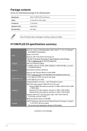
... 1200 @ 60Hz - Supports DVI-D with maximum resolution of the above items is damaged or missing, contact your retailer. H110M-PLUS D3 specifications summary CPU Chipset Memory Expansion slots Graphics Storage LGA1151 socket for 6th Generation Intel® Core™ i7 / i5 /... 2.0 support depends on the next page) vi Package contents Check your motherboard package for the following items. Motherboard Cables Accessories Application DVD Documentation ASUS H110M-PLUS D3 motherboard 2 x Serial ATA 6.0 Gb/s cables 1 x I/O Shield Support DVD User Guide If any of 4096 x 2160 @ 24Hz /...
... 1200 @ 60Hz - Supports DVI-D with maximum resolution of the above items is damaged or missing, contact your retailer. H110M-PLUS D3 specifications summary CPU Chipset Memory Expansion slots Graphics Storage LGA1151 socket for 6th Generation Intel® Core™ i7 / i5 /... 2.0 support depends on the next page) vi Package contents Check your motherboard package for the following items. Motherboard Cables Accessories Application DVD Documentation ASUS H110M-PLUS D3 motherboard 2 x Serial ATA 6.0 Gb/s cables 1 x I/O Shield Support DVD User Guide If any of 4096 x 2160 @ 24Hz /...
User Guide
Page 7
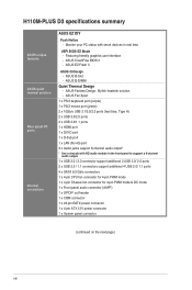
...a smart TV, your build with exceptional clarity and fidelity ASMedia USB 3.1 controllers - Media Streamer app for greater durability! ASUS Disk Unlocker featuring 3TB + HDD support - Audio shielding: Ensures precision analog/digital separation and greatly reduced multi-lateral interference ...at mid-board; 2 ports at the rear panel (teal blue, Type A) Intel® H110 Express Chipset - H110M-PLUS D3 specifications summary LAN Audio USB ASUS unique features Realtek® 8111H Gigabit LAN controller Realtek® ALC887 8-channel High Definition Audio CODEC - Dedicated audio PCB layers...
...a smart TV, your build with exceptional clarity and fidelity ASMedia USB 3.1 controllers - Media Streamer app for greater durability! ASUS Disk Unlocker featuring 3TB + HDD support - Audio shielding: Ensures precision analog/digital separation and greatly reduced multi-lateral interference ...at mid-board; 2 ports at the rear panel (teal blue, Type A) Intel® H110 Express Chipset - H110M-PLUS D3 specifications summary LAN Audio USB ASUS unique features Realtek® 8111H Gigabit LAN controller Realtek® ALC887 8-channel High Definition Audio CODEC - Dedicated audio PCB layers...
User Guide
Page 8
H110M-PLUS D3 specifications summary ASUS unique features ASUS quiet thermal solution Rear panel I/O ports Internal connectors ASUS EZ DIY Push Notice - ASUS CrashFree BIOS 3 - ASUS Fan Xpert 1 x PS/2 keyboard port (purple) 1 x PS/2 mouse port (green) 2 x 10Gb/s USB 3.1/3.0/2.0 ports (teal blue, Type A) 2 x... (continued on the next page) viii Featuring friendly graphics user interface - ASUS EZ Flash 3 ASUS Q-Design - ASUS Q-DIMM Quiet Thermal Design - ASUS Fanless Design: Stylish heatsink solution - ASUS Q-Slot - Monitor your PC status with HD audio module in real time...
H110M-PLUS D3 specifications summary ASUS unique features ASUS quiet thermal solution Rear panel I/O ports Internal connectors ASUS EZ DIY Push Notice - ASUS CrashFree BIOS 3 - ASUS Fan Xpert 1 x PS/2 keyboard port (purple) 1 x PS/2 mouse port (green) 2 x 10Gb/s USB 3.1/3.0/2.0 ports (teal blue, Type A) 2 x... (continued on the next page) viii Featuring friendly graphics user interface - ASUS EZ Flash 3 ASUS Q-Design - ASUS Q-DIMM Quiet Thermal Design - ASUS Fanless Design: Stylish heatsink solution - ASUS Q-Slot - Monitor your PC status with HD audio module in real time...
User Guide
Page 9
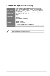
...are subject to install Windows® 7. H110M-PLUS D3 specifications summary BIOS features Manageability Support DVD OS support Form factor 128 Mb Flash ROM, UEFI AMI BIOS, PnP, DMI 2.0, WfM2.0, SM BIOS 3.0, ACPI 5.0, Multi-language BIOS, ASUS EZ Flash 3, ASUS CrashFree BIOS 3, My Favorites, Quick Note, ...Last Modified Log, F12 PrintScreen function, and ASUS DRAM SPD (Serial Presence Detect) memory information WfM 2.0, DMI 2.0, WOL by PME, PXE ...
...are subject to install Windows® 7. H110M-PLUS D3 specifications summary BIOS features Manageability Support DVD OS support Form factor 128 Mb Flash ROM, UEFI AMI BIOS, PnP, DMI 2.0, WfM2.0, SM BIOS 3.0, ACPI 5.0, Multi-language BIOS, ASUS EZ Flash 3, ASUS CrashFree BIOS 3, My Favorites, Quick Note, ...Last Modified Log, F12 PrintScreen function, and ASUS DRAM SPD (Serial Presence Detect) memory information WfM 2.0, DMI 2.0, WOL by PME, PXE ...
User Guide
Page 11
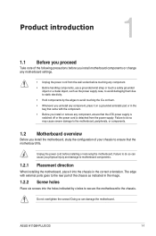
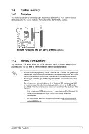
... rear part of the following precautions before you install motherboard components or change any motherboard settings. • Unplug the power cord from the power supply. ASUS H110M-PLUS D3 1-1 Product introduction 1 1.1 Before you proceed Take note of the chassis as the power supply case, to avoid damaging them . • Whenever you uninstall any...
... rear part of the following precautions before you install motherboard components or change any motherboard settings. • Unplug the power cord from the power supply. ASUS H110M-PLUS D3 1-1 Product introduction 1 1.1 Before you proceed Take note of the chassis as the power supply case, to avoid damaging them . • Whenever you uninstall any...
User Guide
Page 12
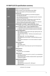
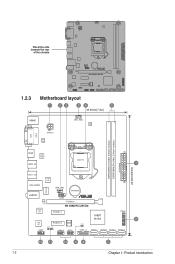
Place this side towards the rear of the chassis H110M-PLUS D3 1.2.3 Motherboard layout 1 23 24 5 18.55cm(7.3in) DVI VGA KBMS ATX12V RTD 2168 CPU_FAN DIGI +VRM DDR3 DIMM_A1 (64bit, 240-pin module) DDR3 DIMM_B1 (64bit,...-pin module) EATXPWR 22.62cm(8.9in) 1-2 HDMI ASM 1442K LGA1151 USB3_34 1 USB3.1_E12 ASM 1142 LANGuard LAN_USB56 CHA_FAN BATTERY AUDIO COM PCIEX16 Realtek 8111H H110M-PLUS D3 Super I/O ALC 887 PCIEX1_1 PCIEX1_2 128Mb BIOS CLRTC Intel® H110 PANEL 6 AAFP SPDIF_OUT USB910 USB78 USB3_12 SATA6G_1 SATA6G_2 SATA6G_3 SATA6G_4 12 11 10 9 8 7 ...
Place this side towards the rear of the chassis H110M-PLUS D3 1.2.3 Motherboard layout 1 23 24 5 18.55cm(7.3in) DVI VGA KBMS ATX12V RTD 2168 CPU_FAN DIGI +VRM DDR3 DIMM_A1 (64bit, 240-pin module) DDR3 DIMM_B1 (64bit,...-pin module) EATXPWR 22.62cm(8.9in) 1-2 HDMI ASM 1442K LGA1151 USB3_34 1 USB3.1_E12 ASM 1142 LANGuard LAN_USB56 CHA_FAN BATTERY AUDIO COM PCIEX16 Realtek 8111H H110M-PLUS D3 Super I/O ALC 887 PCIEX1_1 PCIEX1_2 128Mb BIOS CLRTC Intel® H110 PANEL 6 AAFP SPDIF_OUT USB910 USB78 USB3_12 SATA6G_1 SATA6G_2 SATA6G_3 SATA6G_4 12 11 10 9 8 7 ...
User Guide
Page 13
... 5. Serial port connector (10-1 pin COM) 4. Intel® H110 Serial ATA 6.0 Gb/s connector (7-pin SATA6G_1~4) 8. Digital audio connector (4-1 pin SPDIF_OUT) 12. H110M-PLUS D3 H110M-PLUS D3 CPU socket LGA1151 ASUS H110M-PLUS D3 1-3 DDR3 DIMM slots 6. Clear RTC RAM (2-pin CLRTC) 10. CPU and chassis fan connectors (4-pin CPU_FAN, 4-pin CHA_FAN) 3. System panel connector (20-5 pin...
... 5. Serial port connector (10-1 pin COM) 4. Intel® H110 Serial ATA 6.0 Gb/s connector (7-pin SATA6G_1~4) 8. Digital audio connector (4-1 pin SPDIF_OUT) 12. H110M-PLUS D3 H110M-PLUS D3 CPU socket LGA1151 ASUS H110M-PLUS D3 1-3 DDR3 DIMM slots 6. Clear RTC RAM (2-pin CLRTC) 10. CPU and chassis fan connectors (4-pin CPU_FAN, 4-pin CHA_FAN) 3. System panel connector (20-5 pin...

User Guide
Page 15
ASUS H110M-PLUS D3 1-5 4 C 5 A B 1.3.2 CPU heatsink and fan assembly installation Apply the Thermal Interface Material to the CPU heatsink and CPU before you install the heatsink and fan if necessary.
ASUS H110M-PLUS D3 1-5 4 C 5 A B 1.3.2 CPU heatsink and fan assembly installation Apply the Thermal Interface Material to the CPU heatsink and CPU before you install the heatsink and fan if necessary.
User Guide
Page 17
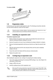
... the Microsoft® support site at http://support.microsoft. com/kb/929605/en-us. ASUS H110M-PLUS D3 1-7 You can be about 3GB or less. The system maps the total size of the DDR3 DIMM sockets: H110M-PLUS D3 H110M-PLUS D3 240-pin DDR3 DIMM sockets 1.4.2 Memory configurations You may install varying memory sizes in Channel...
... the Microsoft® support site at http://support.microsoft. com/kb/929605/en-us. ASUS H110M-PLUS D3 1-7 You can be about 3GB or less. The system maps the total size of the DDR3 DIMM sockets: H110M-PLUS D3 H110M-PLUS D3 240-pin DDR3 DIMM sockets 1.4.2 Memory configurations You may install varying memory sizes in Channel...
User Guide
Page 19
.... Failure to do not need to the card. 3. Otherwise, conflicts will arise between the two PCI groups, making the system unstable and the card inoperable. ASUS H110M-PLUS D3 1-9
.... Failure to do not need to the card. 3. Otherwise, conflicts will arise between the two PCI groups, making the system unstable and the card inoperable. ASUS H110M-PLUS D3 1-9
User Guide
Page 21
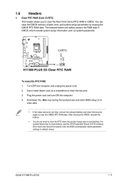
..., which include system setup information such as a screwdriver to default values. Plug the power cord and turn ON the computer. 4. CLRTC H110M-PLUS D3 PIN 1 H110M-PLUS D3 Clear RTC RAM To erase the RTC RAM: 1. For system failure due to re- Turn OFF the computer and unplug the power cord. ...3. Shut down the key during the boot process and enter BIOS setup to overclocking, use the CPU Parameter Recall (C.P.R.) feature. +3V_BAT GND 1.6 Headers 1. ASUS H110M-PLUS D3 1-11 You can clear the CMOS memory of date, time, and system setup parameters by erasing the CMOS RTC RAM data.
..., which include system setup information such as a screwdriver to default values. Plug the power cord and turn ON the computer. 4. CLRTC H110M-PLUS D3 PIN 1 H110M-PLUS D3 Clear RTC RAM To erase the RTC RAM: 1. For system failure due to re- Turn OFF the computer and unplug the power cord. ...3. Shut down the key during the boot process and enter BIOS setup to overclocking, use the CPU Parameter Recall (C.P.R.) feature. +3V_BAT GND 1.6 Headers 1. ASUS H110M-PLUS D3 1-11 You can clear the CMOS memory of date, time, and system setup parameters by erasing the CMOS RTC RAM data.
User Guide
Page 23
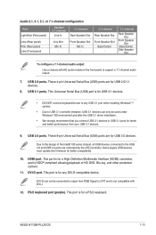
... Windows® OS environment and after the USB 3.1 driver installation. • We strongly recommend that you connect USB 3.1 devices to support a 7.1-channel audio output. 7. ASUS H110M-PLUS D3 1-13 These 4-pin Universal Serial Bus (USB) ports are for USB 2.0/1.1 devices. 8. This Universal Serial Bus (USB) port is not compatible with HD audio module...
... Windows® OS environment and after the USB 3.1 driver installation. • We strongly recommend that you connect USB 3.1 devices to support a 7.1-channel audio output. 7. ASUS H110M-PLUS D3 1-13 These 4-pin Universal Serial Bus (USB) ports are for USB 2.0/1.1 devices. 8. This Universal Serial Bus (USB) port is not compatible with HD audio module...

User Guide
Page 24
Connect the serial port module cable to this connector, then install the module to a slot opening at the back of the system chassis. COM PIN 1 H110M-PLUS D3 H110M-PLUS D3 Serial port (COM) connector The COM module is for a serial (COM) port. RXD DTR DSR CTS DCD TXD GND RTS RI 1.7.2 Internal connectors 1. Serial port connector (10-1 pin COM) This connector is purchased separately. 1-14 Chapter 1: Product introduction
Connect the serial port module cable to this connector, then install the module to a slot opening at the back of the system chassis. COM PIN 1 H110M-PLUS D3 H110M-PLUS D3 Serial port (COM) connector The COM module is for a serial (COM) port. RXD DTR DSR CTS DCD TXD GND RTS RI 1.7.2 Internal connectors 1. Serial port connector (10-1 pin COM) This connector is purchased separately. 1-14 Chapter 1: Product introduction
User Guide
Page 25
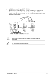
2. ASUS H110M-PLUS D3 1-15 The USB 2.0 module is purchased separately. USB 2.0 connectors (10-1 pin USB78, USB910) These connectors are for USB 2.0 ports. These USB connectors comply with USB 2.0 ... the module to 480Mbps connection speed. USB+5V USB_P7USB_P7+ GND NC USB+5V USB_P9USB_P9+ GND NC USB+5V USB_P8USB_P8+ GND USB+5V USB_P10USB_P10+ GND H110M-PLUS D3 USB910 PIN 1 USB78 PIN 1 H110M-PLUS D3 USB2.0 connectors Never connect a 1394 cable to the USB connectors.
2. ASUS H110M-PLUS D3 1-15 The USB 2.0 module is purchased separately. USB 2.0 connectors (10-1 pin USB78, USB910) These connectors are for USB 2.0 ports. These USB connectors comply with USB 2.0 ... the module to 480Mbps connection speed. USB+5V USB_P7USB_P7+ GND NC USB+5V USB_P9USB_P9+ GND NC USB+5V USB_P8USB_P8+ GND USB+5V USB_P10USB_P10+ GND H110M-PLUS D3 USB910 PIN 1 USB78 PIN 1 H110M-PLUS D3 USB2.0 connectors Never connect a 1394 cable to the USB connectors.
User Guide
Page 26
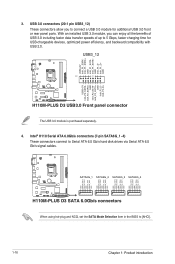
USB3_12 PIN 1 H110M-PLUS D3 H110M-PLUS D3 USB3.0 Front panel connector The USB 3.0 module is purchased separately. 4. USB 3.0 connectors (20-1 pin USB3_12) These connectors allow you can enjoy all the benefits of ... GND GND RSATA_RXP2 RSATA_RXN2 GND RSATA_TXN2 RSATA_TXP2 GND GND RSATA_RXP3 RSATA_RXN3 GND RSATA_TXN3 RSATA_TXP3 GND GND RSATA_RXP4 RSATA_RXN4 GND RSATA_TXN4 RSATA_TXP4 GND H110M-PLUS D3 SATA6G_1 SATA6G_2 SATA6G_3 SATA6G_4 H110M-PLUS D3 SATA 6.0Gb/s connectors When using hot-plug and NCQ, set the SATA Mode Selection item in the BIOS to Serial ATA 6.0 Gb...
USB3_12 PIN 1 H110M-PLUS D3 H110M-PLUS D3 USB3.0 Front panel connector The USB 3.0 module is purchased separately. 4. USB 3.0 connectors (20-1 pin USB3_12) These connectors allow you can enjoy all the benefits of ... GND GND RSATA_RXP2 RSATA_RXN2 GND RSATA_TXN2 RSATA_TXP2 GND GND RSATA_RXP3 RSATA_RXN3 GND RSATA_TXN3 RSATA_TXP3 GND GND RSATA_RXP4 RSATA_RXN4 GND RSATA_TXN4 RSATA_TXP4 GND H110M-PLUS D3 SATA6G_1 SATA6G_2 SATA6G_3 SATA6G_4 H110M-PLUS D3 SATA 6.0Gb/s connectors When using hot-plug and NCQ, set the SATA Mode Selection item in the BIOS to Serial ATA 6.0 Gb...
User Guide
Page 27
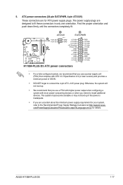
Find the proper orientation and push down firmly until the connectors completely fit. ASUS H110M-PLUS D3 1-17 com/PowerSupplyCalculator/PSCalculator.aspx?SLanguage=en-us for ATX power supply plugs. H110M-PLUS D3 A B ATX12V EATXPWR A +12V DC +12V DC B PIN 1 GND +3 Volts GND +12 Volts +12 Volts +...Volts GND +3 Volts +3 Volts PIN 1 GND +5 Volts +5 Volts +5 Volts -5 Volts GND GND GND PSON# GND -12 Volts +3 Volts H110M-PLUS D3 ATX power connectors • For a fully configured system, we recommend that you use a power supply unit (PSU) that you use a PSU with ...
Find the proper orientation and push down firmly until the connectors completely fit. ASUS H110M-PLUS D3 1-17 com/PowerSupplyCalculator/PSCalculator.aspx?SLanguage=en-us for ATX power supply plugs. H110M-PLUS D3 A B ATX12V EATXPWR A +12V DC +12V DC B PIN 1 GND +3 Volts GND +12 Volts +12 Volts +...Volts GND +3 Volts +3 Volts PIN 1 GND +5 Volts +5 Volts +5 Volts -5 Volts GND GND GND PSON# GND -12 Volts +3 Volts H110M-PLUS D3 ATX power connectors • For a fully configured system, we recommend that you use a power supply unit (PSU) that you use a PSU with ...
User Guide
Page 28
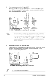
... to this connector, set the item to a slot opening at the back of the system chassis. +5V SPDIFOUT GND H110M-PLUS D3 SPDIF_OUT H110M-PLUS D3 Digital audio connector The S/PDIF module is set the Front Panel Type item in the BIOS setup to this connector is purchased separately... 1 PIN 1 MIC2 MICPWR Line out_R NC Line out_L PORT1 L PORT1 R PORT2 R SENSE_SEND PORT2 L H110M-PLUS D3 HD-audio-compliant Legacy AC'97 pin definition compliant definition H110M-PLUS D3 Front panel audio connector • We recommend that you connect a high-definition front panel audio module to this ...
... to this connector, set the item to a slot opening at the back of the system chassis. +5V SPDIFOUT GND H110M-PLUS D3 SPDIF_OUT H110M-PLUS D3 Digital audio connector The S/PDIF module is set the Front Panel Type item in the BIOS setup to this connector is purchased separately... 1 PIN 1 MIC2 MICPWR Line out_R NC Line out_L PORT1 L PORT1 R PORT2 R SENSE_SEND PORT2 L H110M-PLUS D3 HD-audio-compliant Legacy AC'97 pin definition compliant definition H110M-PLUS D3 Front panel audio connector • We recommend that you connect a high-definition front panel audio module to this ...

User Guide
Page 29
ASUS H110M-PLUS D3 1-19 Do not place jumper caps on the motherboard, ensuring that the black wire of each cable matches the ground pin of maximum 1A (12 W) ... inside the system may damage the motherboard components. These are not jumpers! The CPU_FAN connector supports a CPU fan of the connector CPU_FAN CHA_FAN H110M-PLUS D3 H110M-PLUS D3 Fan connectors Do not forget to connect the fan cables to the fan connectors on the fan connectors! CPU and chassis fan connectors (4-pin CPU_FAN...
ASUS H110M-PLUS D3 1-19 Do not place jumper caps on the motherboard, ensuring that the black wire of each cable matches the ground pin of maximum 1A (12 W) ... inside the system may damage the motherboard components. These are not jumpers! The CPU_FAN connector supports a CPU fan of the connector CPU_FAN CHA_FAN H110M-PLUS D3 H110M-PLUS D3 Fan connectors Do not forget to connect the fan cables to the fan connectors on the fan connectors! CPU and chassis fan connectors (4-pin CPU_FAN...