
F2A85-M LE User's Manual
Page 12
... AMD® A85X SATA6G_4 SATA6G_3 SATA6G_5 SATA6G_6 SATA6G_7 ALC 887 SPDIF_OUT AAFP PCIEX16_2 LPT USB910 USB78 USB56 USB3_34 CLRTC SPEAKER 64Mb SATA6G_2 BIOS SATA6G_1 F_PANEL ASUS F2A85-M LE motherboard User Guide 2 x Serial ATA 6.0 Gb/s cables 1 x I/O-Shield User Guide Support DVD • If any of the above items is damaged or missing, contact your...
... AMD® A85X SATA6G_4 SATA6G_3 SATA6G_5 SATA6G_6 SATA6G_7 ALC 887 SPDIF_OUT AAFP PCIEX16_2 LPT USB910 USB78 USB56 USB3_34 CLRTC SPEAKER 64Mb SATA6G_2 BIOS SATA6G_1 F_PANEL ASUS F2A85-M LE motherboard User Guide 2 x Serial ATA 6.0 Gb/s cables 1 x I/O-Shield User Guide Support DVD • If any of the above items is damaged or missing, contact your...

F2A85-M LE User's Manual
Page 13
... ATA (SATA) storage interface, this motherboard delivers up to ten times faster than USB 2.0. CrossFireX™ allows higher antialiasing, anisotropic filtering, shading, and texture settings. ASUS F2A85-M LE 1-1 Complete USB 3.0 integration This motherboard offers you to experience the convenience of the latest plug and play connectivity solution at speed up to enable accelerated...
... ATA (SATA) storage interface, this motherboard delivers up to ten times faster than USB 2.0. CrossFireX™ allows higher antialiasing, anisotropic filtering, shading, and texture settings. ASUS F2A85-M LE 1-1 Complete USB 3.0 integration This motherboard offers you to experience the convenience of the latest plug and play connectivity solution at speed up to enable accelerated...

F2A85-M LE User's Manual
Page 15
... GPU for extreme graphics performance, facilitates flexible frequency adjustments, and easily delivers stable system-level upgrades for the best overclocking settings in different scenarios. ASUS CrashFree BIOS 3 ASUS CrashFree BIOS 3 allows you to configure the overclocking settings, adjust the frequencies and related voltages, remotely control the system via a mobile device, and other... moderates power usage. feature automatically restores the CPU default settings when the system hangs due to open the system chassis and clear the RTC data. ASUS F2A85-M LE 1-3
... GPU for extreme graphics performance, facilitates flexible frequency adjustments, and easily delivers stable system-level upgrades for the best overclocking settings in different scenarios. ASUS CrashFree BIOS 3 ASUS CrashFree BIOS 3 allows you to configure the overclocking settings, adjust the frequencies and related voltages, remotely control the system via a mobile device, and other... moderates power usage. feature automatically restores the CPU default settings when the system hangs due to open the system chassis and clear the RTC data. ASUS F2A85-M LE 1-3
F2A85-M LE User's Manual
Page 17
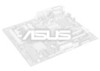
The edge with external ports goes to the chassis. Place this side towards the rear of the chassis as indicated in the correct orientation. F2A85-M LE ASUS F2A85-M LE 1-5 DO NOT overtighten the screws! Doing so can damage the motherboard. 1.3 Motherboard overview 1.3.1 Placement direction When installing the motherboard, ensure that you place it into the chassis in the image below. 1.3.2 Screw holes Place six screws into the holes indicated by circles to secure the motherboard to the rear part of the chassis.
The edge with external ports goes to the chassis. Place this side towards the rear of the chassis as indicated in the correct orientation. F2A85-M LE ASUS F2A85-M LE 1-5 DO NOT overtighten the screws! Doing so can damage the motherboard. 1.3 Motherboard overview 1.3.1 Placement direction When installing the motherboard, ensure that you place it into the chassis in the image below. 1.3.2 Screw holes Place six screws into the holes indicated by circles to secure the motherboard to the rear part of the chassis.

F2A85-M LE User's Manual
Page 19
... (10-1 pin COM) 3. LPT connector (26-1 pin LPT) 14. ATX power connectors (24-pin EATXPWR, 4-pin ATX12V) 4. DDR3 DIMM slots 6. Speaker connector (4-pin SPEAKER) 9. F2A85-M LE F2A85-M LE APU socket FM2 ASUS F2A85-M LE 1-7 Standby power LED (SB_PWR) 11. Digital audio connector (4-1 pin SPDIF_OUT) Page 1-23 1-29 1-24 1-7 1-11 1-25 1-26 1-26 1-20 1-4 1-28 1-28 1-29 1-27...
... (10-1 pin COM) 3. LPT connector (26-1 pin LPT) 14. ATX power connectors (24-pin EATXPWR, 4-pin ATX12V) 4. DDR3 DIMM slots 6. Speaker connector (4-pin SPEAKER) 9. F2A85-M LE F2A85-M LE APU socket FM2 ASUS F2A85-M LE 1-7 Standby power LED (SB_PWR) 11. Digital audio connector (4-1 pin SPDIF_OUT) Page 1-23 1-29 1-24 1-7 1-11 1-25 1-26 1-26 1-20 1-4 1-28 1-28 1-29 1-27...
F2A85-M LE User's Manual
Page 21
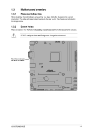
1.4.2 APU heatsink and fan assembly installation Apply the Thermal Interface Material to the APU heatsink and APU before you install the heatsink and fan if necessary. To install the APU heatsink and fan assembly 1 2 3 4 5 ASUS F2A85-M LE 1-9
1.4.2 APU heatsink and fan assembly installation Apply the Thermal Interface Material to the APU heatsink and APU before you install the heatsink and fan if necessary. To install the APU heatsink and fan assembly 1 2 3 4 5 ASUS F2A85-M LE 1-9

F2A85-M LE User's Manual
Page 23
1.5 System memory 1.5.1 Overview This motherboard comes with less power consumption. The figure illustrates the location of the DDR3 DIMM sockets: DIMM_A1 DIMM_B1 F2A85-M LE Channel Channel A Channel B F2A85-M LE 240-pin DDR3 DIMM sockets Sockets DIMM_A1 DIMM_B1 ASUS F2A85-M LE 1-11 A DDR3 module has the same physical dimensions as a DDR2 DIMM but is notched differently to prevent installation on a DDR2 DIMM socket. DDR3 modules are developed for better performance with two Double Data Rate 3 (DDR3) Dual Inline Memory Modules (DIMM) sockets.
1.5 System memory 1.5.1 Overview This motherboard comes with less power consumption. The figure illustrates the location of the DDR3 DIMM sockets: DIMM_A1 DIMM_B1 F2A85-M LE Channel Channel A Channel B F2A85-M LE 240-pin DDR3 DIMM sockets Sockets DIMM_A1 DIMM_B1 ASUS F2A85-M LE 1-11 A DDR3 module has the same physical dimensions as a DDR2 DIMM but is notched differently to prevent installation on a DDR2 DIMM socket. DDR3 modules are developed for better performance with two Double Data Rate 3 (DDR3) Dual Inline Memory Modules (DIMM) sockets.
F2A85-M LE User's Manual
Page 29
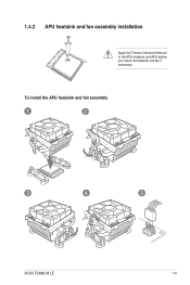
1.5.3 1 Installing a DIMM 2 3 To remove a DIMM B A A ASUS F2A85-M LE 1-17
1.5.3 1 Installing a DIMM 2 3 To remove a DIMM B A A ASUS F2A85-M LE 1-17

F2A85-M LE User's Manual
Page 31
... controller1 - - shared - - - - - shared - - - - - OnChip XHCI controller2 - See page 1-24 for this motherboard A B C D E F G H PCIEx16_1 - - shared - - - HD audio shared - - - - - - - SATA controller - - - shared - - - - shared - - - - - shared - - - - - - OnChip USB OHCI 1/2/3/4 - - ASUS F2A85-M LE 1-19
... controller1 - - shared - - - - - shared - - - - - OnChip XHCI controller2 - See page 1-24 for this motherboard A B C D E F G H PCIEx16_1 - - shared - - - HD audio shared - - - - - - - SATA controller - - - shared - - - - shared - - - - - shared - - - - - - OnChip USB OHCI 1/2/3/4 - - ASUS F2A85-M LE 1-19
F2A85-M LE User's Manual
Page 33
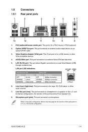
... hard disk drive. 5. Line Out port (lime). In the 4, 6, and 8-channel configurations, the function of the audio ports in 2, 4, 6, or 8-channel configuration. Microphone port (pink). ASUS F2A85-M LE 1-21 PS/2 keyboard/mouse combo port. LAN port LED indications Activity/Link LED Status Description OFF No link ORANGE Linked BLINKING Data activity Speed LED...
... hard disk drive. 5. Line Out port (lime). In the 4, 6, and 8-channel configurations, the function of the audio ports in 2, 4, 6, or 8-channel configuration. Microphone port (pink). ASUS F2A85-M LE 1-21 PS/2 keyboard/mouse combo port. LAN port LED indications Activity/Link LED Status Description OFF No link ORANGE Linked BLINKING Data activity Speed LED...

F2A85-M LE User's Manual
Page 35
...cables to the fan connectors on the fan connectors. • The CPU_FAN connector supports a CPU fan of the connector. 1.8.2 Internal connectors 1. ASUS F2A85-M LE 1-23 Insufficient air flow inside the system may damage the motherboard components. DO NOT place jumper caps on the motherboard, ensuring that you install...the CPU_FAN connector support the ASUS Fan Xpert feature. • If you plug the rear chassis fan cable to the fan connectors. These are not jumpers! PWR_FAN CPU_FAN Rotation +12V GND CPU FAN PWM CPU FAN IN CPU FAN PWR GND F2A85-M LE CHA_FAN CHA FAN DC Mode ...
...cables to the fan connectors on the fan connectors. • The CPU_FAN connector supports a CPU fan of the connector. 1.8.2 Internal connectors 1. ASUS F2A85-M LE 1-23 Insufficient air flow inside the system may damage the motherboard components. DO NOT place jumper caps on the motherboard, ensuring that you install...the CPU_FAN connector support the ASUS Fan Xpert feature. • If you plug the rear chassis fan cable to the fan connectors. These are not jumpers! PWR_FAN CPU_FAN Rotation +12V GND CPU FAN PWM CPU FAN IN CPU FAN PWR GND F2A85-M LE CHA_FAN CHA FAN DC Mode ...

F2A85-M LE User's Manual
Page 37
...onboard controller. SATA6G_4 SATA6G_7 GND RSATA_TXP7 RSATA_TXN7 GND RSATA_RXN7 RSATA_RXP7 GND GND RSATA_RXP4 RSATA_RXN4 GND RSATA_TXN4 RSATA_TXP4 GND F2A85-M LE SATA6G_3 SATA6G_2 SATA6G_1 GND RSATA_RXP2 RSATA_RXN2 GND RSATA_TXN2 RSATA_TXP2 GND GND RSATA_RXP3 RSATA_RXN3 GND RSATA_TXN3 RSATA_TXP3 GND SATA6G_6 GND... GND RSATA_RXN6 RSATA_RXP6 GND SATA6G_5 GND RSATA_TXP5 RSATA_TXN5 GND RSATA_RXN5 RSATA_RXP5 GND GND RSATA_RXP1 RSATA_RXN1 GND RSATA_TXN1 RSATA_TXP1 GND F2A85-M LE SATA 6.0Gb/s connectors • These connectors are using Windows® XP SP3 or later version. •...
...onboard controller. SATA6G_4 SATA6G_7 GND RSATA_TXP7 RSATA_TXN7 GND RSATA_RXN7 RSATA_RXP7 GND GND RSATA_RXP4 RSATA_RXN4 GND RSATA_TXN4 RSATA_TXP4 GND F2A85-M LE SATA6G_3 SATA6G_2 SATA6G_1 GND RSATA_RXP2 RSATA_RXN2 GND RSATA_TXN2 RSATA_TXP2 GND GND RSATA_RXP3 RSATA_RXN3 GND RSATA_TXN3 RSATA_TXP3 GND SATA6G_6 GND... GND RSATA_RXN6 RSATA_RXP6 GND SATA6G_5 GND RSATA_TXP5 RSATA_TXN5 GND RSATA_RXN5 RSATA_RXP5 GND GND RSATA_RXP1 RSATA_RXN1 GND RSATA_TXN1 RSATA_TXP1 GND F2A85-M LE SATA 6.0Gb/s connectors • These connectors are using Windows® XP SP3 or later version. •...

F2A85-M LE User's Manual
Page 39
... audio connector The S/PDIF module is for a chassis-mounted front panel audio I /O module cable to [HD]. ASUS F2A85-M LE 1-27 Connect one end of the motherboard high-definition audio capability. • If you want to connect a high definition front panel ... NC NC AAFP PIN 1 MIC2 MICPWR Line out_R NC Line out_L PORT1 L PORT1 R PORT2 R SENSE_SEND PORT2 L F2A85-M LE HD-audio-compliant Legacy AC'97 pin definition compliant definition F2A85-M LE Front panel audio connector • We recommend that supports either High Definition Audio or AC`97 audio standard. Digital audio...
... audio connector The S/PDIF module is for a chassis-mounted front panel audio I /O module cable to [HD]. ASUS F2A85-M LE 1-27 Connect one end of the motherboard high-definition audio capability. • If you want to connect a high definition front panel ... NC NC AAFP PIN 1 MIC2 MICPWR Line out_R NC Line out_L PORT1 L PORT1 R PORT2 R SENSE_SEND PORT2 L F2A85-M LE HD-audio-compliant Legacy AC'97 pin definition compliant definition F2A85-M LE Front panel audio connector • We recommend that supports either High Definition Audio or AC`97 audio standard. Digital audio...
F2A85-M LE User's Manual
Page 41
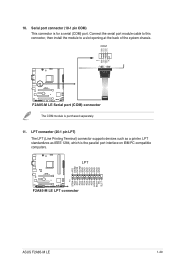
... ERR# INIT# SLIN# GND GND GND GND GND GND GND GND F2A85-M LE LPT PIN 1 STB# PD0 PD1 PD2 PD3 PD4 PD5 PD6 PD7 ACK# BUSY PE SLCT F2A85-M LE LPT connector ASUS F2A85-M LE 1-29 COM PIN 1 RXD DTR DSR CTS DCD TXD GND RTS RI F2A85-M LE F2A85-M LE Serial port (COM) connector The COM module is for a serial...
... ERR# INIT# SLIN# GND GND GND GND GND GND GND GND F2A85-M LE LPT PIN 1 STB# PD0 PD1 PD2 PD3 PD4 PD5 PD6 PD7 ACK# BUSY PE SLCT F2A85-M LE LPT connector ASUS F2A85-M LE 1-29 COM PIN 1 RXD DTR DSR CTS DCD TXD GND RTS RI F2A85-M LE F2A85-M LE Serial port (COM) connector The COM module is for a serial...

F2A85-M LE User's Manual
Page 44
...the BIOS to update the BIOS without using EZ Flash 2: 1. Updating from the ASUS website at www.asus.com. Select the ASUS FTP site nearest you to prevent system boot failure! 2-2 ASUS F2A85-M LE To update the BIOS using an OS‑based utility. Follow the onscreen instructions ...to complete the updating process. 2.1.2 ASUS EZ Flash 2 The ASUS EZ Flash 2 feature allows you to download then click Next. Before you ...
...the BIOS to update the BIOS without using EZ Flash 2: 1. Updating from the ASUS website at www.asus.com. Select the ASUS FTP site nearest you to prevent system boot failure! 2-2 ASUS F2A85-M LE To update the BIOS using an OS‑based utility. Follow the onscreen instructions ...to complete the updating process. 2.1.2 ASUS EZ Flash 2 The ASUS EZ Flash 2 feature allows you to download then click Next. Before you ...

F2A85-M LE User's Manual
Page 46
... item by pressing the item number. 4. At the FreeDOS prompt, type d: and press to switch the disk from the ASUS website at http://support.asus.com and save the BIOS file and BIOS Updater to boot using defaults 3. Before updating BIOS 1. Download the latest BIOS... Updater to Drive D (USB flash drive). Welcome to update BIOS in NTFS format. 3. C:\>d: D:\> 2-4 ASUS F2A85-M LE The succeeding utility screens are for reference only. 2.1.4 ASUS BIOS Updater The ASUS BIOS Updater allows you to FreeDOS (http://www.freedos.org)! The actual utility screen displays may not be same...
... item by pressing the item number. 4. At the FreeDOS prompt, type d: and press to switch the disk from the ASUS website at http://support.asus.com and save the BIOS file and BIOS Updater to boot using defaults 3. Before updating BIOS 1. Download the latest BIOS... Updater to Drive D (USB flash drive). Welcome to update BIOS in NTFS format. 3. C:\>d: D:\> 2-4 ASUS F2A85-M LE The succeeding utility screens are for reference only. 2.1.4 ASUS BIOS Updater The ASUS BIOS Updater allows you to FreeDOS (http://www.freedos.org)! The actual utility screen displays may not be same...

F2A85-M LE User's Manual
Page 48
... with its parameters. We recommend to always shut down the system properly from the Exit/Advanced Mode button in the EZ Mode/Advanced Mode screen. 2-6 ASUS F2A85-M LE The BIOS screens include navigation keys and brief online help to enter BIOS Setup using the BIOS Setup program. You can change modes from the...
... with its parameters. We recommend to always shut down the system properly from the Exit/Advanced Mode button in the EZ Mode/Advanced Mode screen. 2-6 ASUS F2A85-M LE The BIOS screens include navigation keys and brief online help to enter BIOS Setup using the BIOS Setup program. You can change modes from the...
F2A85-M LE User's Manual
Page 50
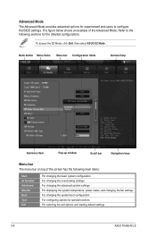
... screen has the following sections for special functions For selecting the exit options and loading default settings 2-8 ASUS F2A85-M LE Refer to configure the BIOS settings. To access the EZ Mode, click Exit, then select ASUS EZ Mode. Advanced Mode The Advanced Mode provides advanced options for experienced end-users to the following main...
... screen has the following sections for special functions For selecting the exit options and loading default settings 2-8 ASUS F2A85-M LE Refer to configure the BIOS settings. To access the EZ Mode, click Exit, then select ASUS EZ Mode. Advanced Mode The Advanced Mode provides advanced options for experienced end-users to the following main...
F2A85-M LE User's Manual
Page 52
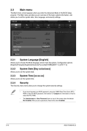
... 1.7 Jumpers for information on how to erase the RTC RAM. • The Administrator or User Password items on top of the screen show Installed. 2-10 ASUS F2A85-M LE Configuration options: [English] [Français] [Español] [Deutsch 2.3.2 System Date [Day xx/xx/xxxx] Allows you to set the system date. 2.3.3 System Time...
... 1.7 Jumpers for information on how to erase the RTC RAM. • The Administrator or User Password items on top of the screen show Installed. 2-10 ASUS F2A85-M LE Configuration options: [English] [Français] [Español] [Deutsch 2.3.2 System Date [Day xx/xx/xxxx] Allows you to set the system date. 2.3.3 System Time...
F2A85-M LE User's Manual
Page 54
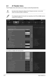
F1: General Help F2: Previous Values F5: Optimized Defaults F10: Save ESC: Exit F12: Print Screen Version 2.10.1208. Copyright (C) 2012 American Megatrends, Inc. 2-12 ASUS F2A85-M LE EFI BIOS Utility - The configuration options for this section vary depending on the motherboard. F1: General Help F2: Previous Values F5: Optimized Defaults F10: Save ...
F1: General Help F2: Previous Values F5: Optimized Defaults F10: Save ESC: Exit F12: Print Screen Version 2.10.1208. Copyright (C) 2012 American Megatrends, Inc. 2-12 ASUS F2A85-M LE EFI BIOS Utility - The configuration options for this section vary depending on the motherboard. F1: General Help F2: Previous Values F5: Optimized Defaults F10: Save ...


