F2A55-M LK2 User's Manual
Page 11
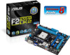
...) DDR3 DIMM_B1 (64bit, 240-pin module) VGA DVI SOCKET FM2 USB34 EATXPWR LAN1_USB12 AUDIO CHA_FAN F2A55-M LK2 PLUS RTL 8111F PCIEX16 PCIEX1_1 Lithium Cell CMOS Power ALC887 Super I/O PCI1 SB_PWR SPDIF_OUTCOM1USBPW5-8 USB78 AAFP AMD® A55 SATA3G_1 SATA3G_2 SPEAKER CLRTC USB56 32Mb BIOS SATA3G_3 SATA3G_4 F_PANEL ASUS F2A55-M LK2 Series motherboard User Guide 2 x Serial ATA 3.0 Gb/s cables...
...) DDR3 DIMM_B1 (64bit, 240-pin module) VGA DVI SOCKET FM2 USB34 EATXPWR LAN1_USB12 AUDIO CHA_FAN F2A55-M LK2 PLUS RTL 8111F PCIEX16 PCIEX1_1 Lithium Cell CMOS Power ALC887 Super I/O PCI1 SB_PWR SPDIF_OUTCOM1USBPW5-8 USB78 AAFP AMD® A55 SATA3G_1 SATA3G_2 SPEAKER CLRTC USB56 32Mb BIOS SATA3G_3 SATA3G_4 F_PANEL ASUS F2A55-M LK2 Series motherboard User Guide 2 x Serial ATA 3.0 Gb/s cables...
F2A55-M LK2 User's Manual
Page 16
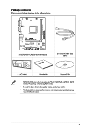
... to avoid touching the ICs on them. • Whenever you uninstall any motherboard component. SB_PWR F2A55-M LK2 PLUS ON OFF Standby Power Powered Off F2A55-M LK2 PLUS Onboard LED 1-4 Chapter 1: Product introduction The illustration below shows the location of the following precautions ...before you install motherboard components or change any motherboard settings. • Unplug the power cord from the wall socket before touching ...
... to avoid touching the ICs on them. • Whenever you uninstall any motherboard component. SB_PWR F2A55-M LK2 PLUS ON OFF Standby Power Powered Off F2A55-M LK2 PLUS Onboard LED 1-4 Chapter 1: Product introduction The illustration below shows the location of the following precautions ...before you install motherboard components or change any motherboard settings. • Unplug the power cord from the wall socket before touching ...
F2A55-M LK2 User's Manual
Page 18
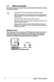
... DIGI +VRM CPU_FAN DDR3 DIMM_A1 (64bit, 240-pin module) DDR3 DIMM_B1 (64bit, 240-pin module) VGA DVI 16 KBPWR USBPW1-4 SOCKET FM2 22.6cm(8.9in) 1 USB34 EATXPWR LAN1_USB12 AUDIO CHA_FAN F2A55-M LK2 PLUS RTL 8111F PCIEX16 PCIEX1_1 Lithium Cell CMOS Power SATA3G_1 AMD® A55 SATA3G_2 6 ALC887 Super I/O PCI1 32Mb BIOS SB_PWR SPDIF_OUTCOM1USBPW5-8 USB78...
... DIGI +VRM CPU_FAN DDR3 DIMM_A1 (64bit, 240-pin module) DDR3 DIMM_B1 (64bit, 240-pin module) VGA DVI 16 KBPWR USBPW1-4 SOCKET FM2 22.6cm(8.9in) 1 USB34 EATXPWR LAN1_USB12 AUDIO CHA_FAN F2A55-M LK2 PLUS RTL 8111F PCIEX16 PCIEX1_1 Lithium Cell CMOS Power SATA3G_1 AMD® A55 SATA3G_2 6 ALC887 Super I/O PCI1 32Mb BIOS SB_PWR SPDIF_OUTCOM1USBPW5-8 USB78...
F2A55-M LK2 User's Manual
Page 19
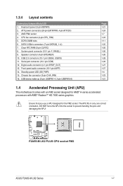
... a APU designed for AMD® A-series accelerated processors with an FM2 socket designed for the FM2 socket. 1.3.4 Layout contents Connectors/Jumpers/Slots/LED 1. Keyboard power (3-pin KBPWR)...socket 4. Digital audio connector (4-1 pin SPDIF_OUT) 13. SATA 3.0Gb/s connectors (7-pin SATA3G_1~4) 7. ATX power connectors (24-pin EATXPWR, 4-pin ATX12V) 3. DO NOT force the APU into the socket to prevent bending the pins and damaging the APU! System panel connector (10-1 pin F_PANEL) 9. CPU fan connector (4-pin CPU_FAN) 5. F2A55-M LK2 PLUS F2A55-M LK2 PLUS CPU socket FM2 ASUS F2A55-M LK2...
... a APU designed for AMD® A-series accelerated processors with an FM2 socket designed for the FM2 socket. 1.3.4 Layout contents Connectors/Jumpers/Slots/LED 1. Keyboard power (3-pin KBPWR)...socket 4. Digital audio connector (4-1 pin SPDIF_OUT) 13. SATA 3.0Gb/s connectors (7-pin SATA3G_1~4) 7. ATX power connectors (24-pin EATXPWR, 4-pin ATX12V) 3. DO NOT force the APU into the socket to prevent bending the pins and damaging the APU! System panel connector (10-1 pin F_PANEL) 9. CPU fan connector (4-pin CPU_FAN) 5. F2A55-M LK2 PLUS F2A55-M LK2 PLUS CPU socket FM2 ASUS F2A55-M LK2...
F2A55-M LK2 User's Manual
Page 23
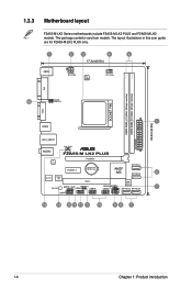
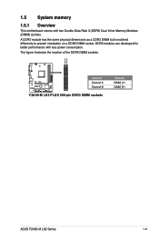
A DDR3 module has the same physical dimensions as a DDR2 DIMM but is notched differently to prevent installation on a DDR2 DIMM socket. DDR3 modules are developed for better performance with two Double Data Rate 3 (DDR3) Dual Inline Memory Modules (DIMM) sockets. The figure illustrates the location of the DDR3 DIMM sockets: DIMM_A1 DIMM_B1 F2A55-M LK2 PLUS Channel Channel A Channel B F2A55-M LK2 PLUS 240-pin DDR3 DIMM sockets Sockets DIMM_A1 DIMM_B1 ASUS F2A55-M LK2 Series 1-11 1.5 System memory 1.5.1 Overview This motherboard comes with less power consumption.
A DDR3 module has the same physical dimensions as a DDR2 DIMM but is notched differently to prevent installation on a DDR2 DIMM socket. DDR3 modules are developed for better performance with two Double Data Rate 3 (DDR3) Dual Inline Memory Modules (DIMM) sockets. The figure illustrates the location of the DDR3 DIMM sockets: DIMM_A1 DIMM_B1 F2A55-M LK2 PLUS Channel Channel A Channel B F2A55-M LK2 PLUS 240-pin DDR3 DIMM sockets Sockets DIMM_A1 DIMM_B1 ASUS F2A55-M LK2 Series 1-11 1.5 System memory 1.5.1 Overview This motherboard comes with less power consumption.


