F2A55-M LE User's Manual
Page 12
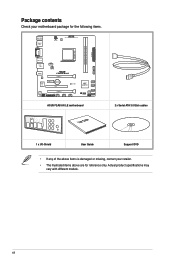
... SB_PWR ALC 887-CG SPDIF_OUT AAFP PCIEX16_2 LPT USB910 USB78 USB56 AMD® A55FCH SATA3G_4 SATA3G_3 CLRTC SPEAKER 64Mb SATA3G_2 BIOS SATA3G_1 F_PANEL SATA6G_5 SATA6G_6 ASUS F2A55-M LE motherboard User Guide 2 x Serial ATA 3.0 Gb/s cables 1 x I/O-Shield User Guide Support DVD • If any of the above items is damaged or missing, contact your...
... SB_PWR ALC 887-CG SPDIF_OUT AAFP PCIEX16_2 LPT USB910 USB78 USB56 AMD® A55FCH SATA3G_4 SATA3G_3 CLRTC SPEAKER 64Mb SATA3G_2 BIOS SATA3G_1 F_PANEL SATA6G_5 SATA6G_6 ASUS F2A55-M LE motherboard User Guide 2 x Serial ATA 3.0 Gb/s cables 1 x I/O-Shield User Guide Support DVD • If any of the above items is damaged or missing, contact your...
F2A55-M LE User's Manual
Page 13
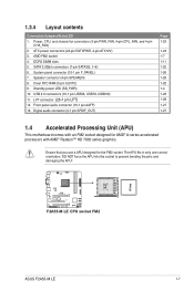
...174; A55 chipset employ precise digital voltage regulation for the APU, called DIGI+VRM (Voltage Regulation Modules) digital power design. ASUS F2A55-M LE 1-1 CrossFireX™ allows higher antialiasing, anisotropic filtering, shading, and texture settings. The APU voltage and VRM Frequency are ...rate up to enable accelerated performance and an industry-leading visual experience. Engineered and tested to assure unimitigated performance, ASUS A55 boards with rendering speed, eliminating the need to scale down screen resolution to 5GT/s. Adjust your display configurations...
...174; A55 chipset employ precise digital voltage regulation for the APU, called DIGI+VRM (Voltage Regulation Modules) digital power design. ASUS F2A55-M LE 1-1 CrossFireX™ allows higher antialiasing, anisotropic filtering, shading, and texture settings. The APU voltage and VRM Frequency are ...rate up to enable accelerated performance and an industry-leading visual experience. Engineered and tested to assure unimitigated performance, ASUS A55 boards with rendering speed, eliminating the need to scale down screen resolution to 5GT/s. Adjust your display configurations...
F2A55-M LE User's Manual
Page 15
... environmental impacts. AI Suite II With its user interface, ASUS AI Suite II integrates several ASUS utilities and allows you to restore a corrupted BIOS file from switching power supply unit (PSU). ASUS F2A55-M LE 1-3 eliminates the need to launch and operate these utilities simultaneously. ASUS CrashFree BIOS 3 ASUS CrashFree BIOS 3 allows you to open the system chassis...
... environmental impacts. AI Suite II With its user interface, ASUS AI Suite II integrates several ASUS utilities and allows you to restore a corrupted BIOS file from switching power supply unit (PSU). ASUS F2A55-M LE 1-3 eliminates the need to launch and operate these utilities simultaneously. ASUS CrashFree BIOS 3 ASUS CrashFree BIOS 3 allows you to open the system chassis...

F2A55-M LE User's Manual
Page 17
The edge with external ports goes to the chassis. Place this side towards the rear of the chassis as indicated in the correct orientation. Doing so can damage the motherboard. DO NOT overtighten the screws! F2A55-M LE ASUS F2A55-M LE 1-5 1.3 Motherboard overview 1.3.1 Placement direction When installing the motherboard, ensure that you place it into the chassis in the image below. 1.3.2 Screw holes Place six screws into the holes indicated by circles to secure the motherboard to the rear part of the chassis.
The edge with external ports goes to the chassis. Place this side towards the rear of the chassis as indicated in the correct orientation. Doing so can damage the motherboard. DO NOT overtighten the screws! F2A55-M LE ASUS F2A55-M LE 1-5 1.3 Motherboard overview 1.3.1 Placement direction When installing the motherboard, ensure that you place it into the chassis in the image below. 1.3.2 Screw holes Place six screws into the holes indicated by circles to secure the motherboard to the rear part of the chassis.
F2A55-M LE User's Manual
Page 19
... a APU designed for AMD® A-series accelerated processors with an FM2 socket designed for the FM2 socket. AMD FM2 socket 4. Speaker connector (4-pin SPEAKER) 8. F2A55-M LE F2A55-M LE CPU socket FM2 ASUS F2A55-M LE 1-7 ATX power connectors (24-pin EATXPWR, 4-pin ATX12V) 3. Digital audio connector (4-1 pin SPDIF_OUT) Page 1-23 1-24 1-7 1-11 1-25 1-26 1-26 1-20 1-4 1-28 1-28...
... a APU designed for AMD® A-series accelerated processors with an FM2 socket designed for the FM2 socket. AMD FM2 socket 4. Speaker connector (4-pin SPEAKER) 8. F2A55-M LE F2A55-M LE CPU socket FM2 ASUS F2A55-M LE 1-7 ATX power connectors (24-pin EATXPWR, 4-pin ATX12V) 3. Digital audio connector (4-1 pin SPDIF_OUT) Page 1-23 1-24 1-7 1-11 1-25 1-26 1-26 1-20 1-4 1-28 1-28...
F2A55-M LE User's Manual
Page 21
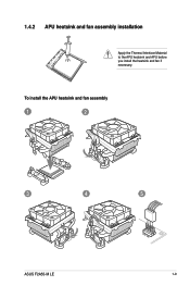
To install the APU heatsink and fan assembly 1 2 3 4 5 ASUS F2A55-M LE 1-9 1.4.2 APU heatsink and fan assembly installation Apply the Thermal Interface Material to the APU heatsink and APU before you install the heatsink and fan if necessary.
To install the APU heatsink and fan assembly 1 2 3 4 5 ASUS F2A55-M LE 1-9 1.4.2 APU heatsink and fan assembly installation Apply the Thermal Interface Material to the APU heatsink and APU before you install the heatsink and fan if necessary.

F2A55-M LE User's Manual
Page 23
1.5 System memory 1.5.1 Overview This motherboard comes with less power consumption. The figure illustrates the location of the DDR3 DIMM sockets: DIMM_A1 DIMM_B1 F2A55-M LE Channel Channel A Channel B F2A55-M LE 240-pin DDR3 DIMM sockets Sockets DIMM_A1 DIMM_B1 ASUS F2A55-M LE 1-11 A DDR3 module has the same physical dimensions as a DDR2 DIMM but is notched differently to prevent installation on a DDR2 DIMM socket. DDR3 modules are developed for better performance with two Double Data Rate 3 (DDR3) Dual Inline Memory Modules (DIMM) sockets.
1.5 System memory 1.5.1 Overview This motherboard comes with less power consumption. The figure illustrates the location of the DDR3 DIMM sockets: DIMM_A1 DIMM_B1 F2A55-M LE Channel Channel A Channel B F2A55-M LE 240-pin DDR3 DIMM sockets Sockets DIMM_A1 DIMM_B1 ASUS F2A55-M LE 1-11 A DDR3 module has the same physical dimensions as a DDR2 DIMM but is notched differently to prevent installation on a DDR2 DIMM socket. DDR3 modules are developed for better performance with two Double Data Rate 3 (DDR3) Dual Inline Memory Modules (DIMM) sockets.
F2A55-M LE User's Manual
Page 25
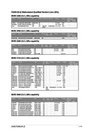
F2A55-M LE Motherboard Qualified Vendors Lists (QVL) DDR3 2400 (O.C.) MHz capability Vendors Part No. Size SS/DS Chip Brand Chip NO. Voltage 1.65V DIMM socket support (optional) ... - - - 1.65V · · KINGSTON KHX2000C9AD3W1K3/6GX(XMP) 6GB ( 3x 2GB ) DS - - - 1.65V · · KINGSTON KHX2000C9AD3T1K3/6GX(XMP) 6GB (3x 2GB ) DS - - - 1.65V · · ASUS F2A55-M LE 1-13 Timing Voltage G.SKILL F3-19200CL9D-4GBPIS(XMP) 4GB(2x 2GB) DS KINGMAX FLLE88F-C8KKAA HAIS(XMP) 2GB SS Team TXD34096M2400HC9N-L 4GB DS - KINGSTON KHX2250C9D3T1K2...
F2A55-M LE Motherboard Qualified Vendors Lists (QVL) DDR3 2400 (O.C.) MHz capability Vendors Part No. Size SS/DS Chip Brand Chip NO. Voltage 1.65V DIMM socket support (optional) ... - - - 1.65V · · KINGSTON KHX2000C9AD3W1K3/6GX(XMP) 6GB ( 3x 2GB ) DS - - - 1.65V · · KINGSTON KHX2000C9AD3T1K3/6GX(XMP) 6GB (3x 2GB ) DS - - - 1.65V · · ASUS F2A55-M LE 1-13 Timing Voltage G.SKILL F3-19200CL9D-4GBPIS(XMP) 4GB(2x 2GB) DS KINGMAX FLLE88F-C8KKAA HAIS(XMP) 2GB SS Team TXD34096M2400HC9N-L 4GB DS - KINGSTON KHX2250C9D3T1K2...

F2A55-M LE User's Manual
Page 29
1.5.3 1 Installing a DIMM 2 3 To remove a DIMM B A A ASUS F2A55-M LE 1-17
1.5.3 1 Installing a DIMM 2 3 To remove a DIMM B A A ASUS F2A55-M LE 1-17

F2A55-M LE User's Manual
Page 31
... card to the motherboard connector labeled CHA_FAN when using multiple graphics cards for this motherboard A B C D E F G H PCIEx16_1 - - On Chip XHCI controller2 - shared - - - - On Chip XHCI controller1 - - ASUS F2A55-M LE 1-19 PCI1 slot - - - - HD audio shared - - - - - - - shared - - - - - - PCIEx1_1 shared - - - - - - - On Chip USB OHCI 1/2/3/4 - - 1.6.5 PCI Express x16 slots This motherboard supports two PCI Express x16 graphics...
... card to the motherboard connector labeled CHA_FAN when using multiple graphics cards for this motherboard A B C D E F G H PCIEx16_1 - - On Chip XHCI controller2 - shared - - - - On Chip XHCI controller1 - - ASUS F2A55-M LE 1-19 PCI1 slot - - - - HD audio shared - - - - - - - shared - - - - - - PCIEx1_1 shared - - - - - - - On Chip USB OHCI 1/2/3/4 - - 1.6.5 PCI Express x16 slots This motherboard supports two PCI Express x16 graphics...

F2A55-M LE User's Manual
Page 33
... monitor or other audio sources. 6. In the 4, 6, and 8-channel configurations, the function of the audio ports in 2, 4, 6, or 8-channel configuration. Line In port (light blue). ASUS F2A55-M LE 1-21 This port connects an external audio output device via an optical S/PDIF cable. 3. 1.8 Connectors 1.8.1 Rear panel ports 1 2 3 4 56 12 11 10 9 8 7 1. This port is...
... monitor or other audio sources. 6. In the 4, 6, and 8-channel configurations, the function of the audio ports in 2, 4, 6, or 8-channel configuration. Line In port (light blue). ASUS F2A55-M LE 1-21 This port connects an external audio output device via an optical S/PDIF cable. 3. 1.8 Connectors 1.8.1 Rear panel ports 1 2 3 4 56 12 11 10 9 8 7 1. This port is...

F2A55-M LE User's Manual
Page 35
ASUS F2A55-M LE 1-23 Power, CPU, and chassis fan connectors (3-pin PWR_FAN, 4-pin CPU_FAN, and 4-pin CHA_FAN) ...of each cable matches the ground pin of maximum 2A (24 W) fan power. • Only the CPU_FAN connector support the ASUS Fan Xpert feature. • If you install two VGA cards, we recommend that you plug the rear chassis fan cable ...1. PWR_FAN CPU_FAN CPU FAN PWM CPU FAN IN CPU FAN PWR GND Rotation +12V GND F2A55-M LE CHA_FAN CHA FAN PWM CHA FAN IN CHA FAN PWR GND F2A55-M LE Fan connectors DO NOT forget to connect the fan cables to the motherboard connector labeled CHA_FAN...
ASUS F2A55-M LE 1-23 Power, CPU, and chassis fan connectors (3-pin PWR_FAN, 4-pin CPU_FAN, and 4-pin CHA_FAN) ...of each cable matches the ground pin of maximum 2A (24 W) fan power. • Only the CPU_FAN connector support the ASUS Fan Xpert feature. • If you install two VGA cards, we recommend that you plug the rear chassis fan cable ...1. PWR_FAN CPU_FAN CPU FAN PWM CPU FAN IN CPU FAN PWR GND Rotation +12V GND F2A55-M LE CHA_FAN CHA FAN PWM CHA FAN IN CHA FAN PWR GND F2A55-M LE Fan connectors DO NOT forget to connect the fan cables to the motherboard connector labeled CHA_FAN...

F2A55-M LE User's Manual
Page 37
... connectors, set the type of the SATA connectors in the BIOS to [AHCI]. ASUS F2A55-M LE 1-25 SATA3G_4 GND RSATA_RXP4 RSATA_RXN4 GND RSATA_TXN4 RSATA_TXP4 GND F2A55-M LE SATA3G_3 SATA3G_2 SATA3G_1 GND RSATA_RXP2 RSATA_RXN2 GND RSATA_TXN2 RSATA_TXP2 GND GND RSATA_RXP3 RSATA_RXN3 GND RSATA_TXN3... RSATA_TXN6 GND RSATA_RXN6 RSATA_RXP6 GND SATA3G_5 GND RSATA_TXP5 RSATA_TXN5 GND RSATA_RXN5 RSATA_RXP5 GND GND RSATA_RXP1 RSATA_RXN1 GND RSATA_TXN1 RSATA_TXP1 GND F2A55-M LE SATA 3.0Gb/s connectors • These connectors are using Windows® XP SP3 or later version. • When...
... connectors, set the type of the SATA connectors in the BIOS to [AHCI]. ASUS F2A55-M LE 1-25 SATA3G_4 GND RSATA_RXP4 RSATA_RXN4 GND RSATA_TXN4 RSATA_TXP4 GND F2A55-M LE SATA3G_3 SATA3G_2 SATA3G_1 GND RSATA_RXP2 RSATA_RXN2 GND RSATA_TXN2 RSATA_TXP2 GND GND RSATA_RXP3 RSATA_RXN3 GND RSATA_TXN3... RSATA_TXN6 GND RSATA_RXN6 RSATA_RXP6 GND SATA3G_5 GND RSATA_TXP5 RSATA_TXN5 GND RSATA_RXN5 RSATA_RXP5 GND GND RSATA_RXP1 RSATA_RXN1 GND RSATA_TXN1 RSATA_TXP1 GND F2A55-M LE SATA 3.0Gb/s connectors • These connectors are using Windows® XP SP3 or later version. • When...
F2A55-M LE User's Manual
Page 39
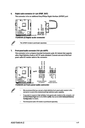
...end of the motherboard high-definition audio capability. • If you want to connect a high definition front panel audio module to [HD]. ASUS F2A55-M LE 1-27 +5V SPDIFOUT GND 6. See section 2.5.5 Onboard Devices Configuration for a chassis-mounted front panel audio I/O module that you connect a... this connector to avail of the front panel audio I /O module is for an additional Sony/Philips Digital Interface (S/PDIF) port. F2A55-M LE SPDIF_OUT F2A55-M LE Digital audio connector The S/PDIF module is for details. • The front panel audio I /O module cable to this connector,...
...end of the motherboard high-definition audio capability. • If you want to connect a high definition front panel audio module to [HD]. ASUS F2A55-M LE 1-27 +5V SPDIFOUT GND 6. See section 2.5.5 Onboard Devices Configuration for a chassis-mounted front panel audio I/O module that you connect a... this connector to avail of the front panel audio I /O module is for an additional Sony/Philips Digital Interface (S/PDIF) port. F2A55-M LE SPDIF_OUT F2A55-M LE Digital audio connector The S/PDIF module is for details. • The front panel audio I /O module cable to this connector,...

F2A55-M LE User's Manual
Page 41
ASUS F2A55-M LE 1-29 COM PIN 1 F2A55-M LE F2A55-M LE Serial port (COM) connector The COM module is for a serial (COM) port. Serial port connector (10-1 pin COM) This connector is purchased separately. RXD DTR DSR CTS DCD TXD GND RTS RI 10. Connect the serial port module cable to this connector, then install the module to a slot opening at the back of the system chassis.
ASUS F2A55-M LE 1-29 COM PIN 1 F2A55-M LE F2A55-M LE Serial port (COM) connector The COM module is for a serial (COM) port. Serial port connector (10-1 pin COM) This connector is purchased separately. RXD DTR DSR CTS DCD TXD GND RTS RI 10. Connect the serial port module cable to this connector, then install the module to a slot opening at the back of the system chassis.
F2A55-M LE User's Manual
Page 44
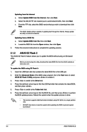
...BIOS file from file, then click Next. Follow the onscreen instructions to complete the updating process. 2.1.2 ASUS EZ Flash 2 The ASUS EZ Flash 2 feature allows you to prevent system boot failure! 2-2 ASUS F2A55-M LE To update the BIOS using FAT 32/16 on a single partition only. • DO NOT shut...From the FTP site, select the BIOS version that contains the latest BIOS file to the Drive field. 4. Go to the Tool menu to select ASUS EZ Flash 2 Utility and press to download then click Next. Updating from a BIOS file a. Before you wish to enable it. 3. Updating from ...
...BIOS file from file, then click Next. Follow the onscreen instructions to complete the updating process. 2.1.2 ASUS EZ Flash 2 The ASUS EZ Flash 2 feature allows you to prevent system boot failure! 2-2 ASUS F2A55-M LE To update the BIOS using FAT 32/16 on a single partition only. • DO NOT shut...From the FTP site, select the BIOS version that contains the latest BIOS file to the Drive field. 4. Go to the Tool menu to select ASUS EZ Flash 2 Utility and press to download then click Next. Updating from a BIOS file a. Before you wish to enable it. 3. Updating from ...
F2A55-M LE User's Manual
Page 46
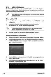
... 1. Boot your computer. Insert the support DVD into the optical drive and select the optical drive as the boot device. C:\>d: D:\> 2-4 ASUS F2A55-M LE Booting the system in FAT32/16 format and single partition. 2. When the Make Disk menu appears, select the FreeDOS command prompt item by ...file and BIOS Updater from Drive C (optical drive) to a hard disk drive or USB flash drive in DOS environment. 2.1.4 ASUS BIOS Updater The ASUS BIOS Updater allows you can use as shown. The succeeding utility screens are for reference only. Turn off the computer and disconnect all...
... 1. Boot your computer. Insert the support DVD into the optical drive and select the optical drive as the boot device. C:\>d: D:\> 2-4 ASUS F2A55-M LE Booting the system in FAT32/16 format and single partition. 2. When the Make Disk menu appears, select the FreeDOS command prompt item by ...file and BIOS Updater from Drive C (optical drive) to a hard disk drive or USB flash drive in DOS environment. 2.1.4 ASUS BIOS Updater The ASUS BIOS Updater allows you can use as shown. The succeeding utility screens are for reference only. Turn off the computer and disconnect all...

F2A55-M LE User's Manual
Page 48
... for reference purposes only, and may not exactly match what you failed to the default value. If you in the EZ Mode/Advanced Mode screen. 2-6 ASUS F2A55-M LE If the system becomes unstable after changing any BIOS setting, try to clear the CMOS and reset the motherboard to enter BIOS Setup using the...
... for reference purposes only, and may not exactly match what you failed to the default value. If you in the EZ Mode/Advanced Mode screen. 2-6 ASUS F2A55-M LE If the system becomes unstable after changing any BIOS setting, try to clear the CMOS and reset the motherboard to enter BIOS Setup using the...

F2A55-M LE User's Manual
Page 50
Refer to configure the BIOS settings. To access the EZ Mode, click Exit, then select ASUS EZ Mode. Menu items Menu bar Configuration fields General help Submenu Pop-up window Scroll bar Navigation keys Menu bar The menu bar on top .... The figure below shows an example of the screen has the following sections for special functions For selecting the exit options and loading default settings 2-8 ASUS F2A55-M LE
Refer to configure the BIOS settings. To access the EZ Mode, click Exit, then select ASUS EZ Mode. Menu items Menu bar Configuration fields General help Submenu Pop-up window Scroll bar Navigation keys Menu bar The menu bar on top .... The figure below shows an example of the screen has the following sections for special functions For selecting the exit options and loading default settings 2-8 ASUS F2A55-M LE

F2A55-M LE User's Manual
Page 52
2.3 Main menu The Main menu screen appears when you enter the Advanced Mode of the screen show Installed. 2-10 ASUS F2A55-M LE After you set a password, these items show the default Not Installed. See section 1.7 Jumpers for information on how to erase the RTC RAM. • The ...
2.3 Main menu The Main menu screen appears when you enter the Advanced Mode of the screen show Installed. 2-10 ASUS F2A55-M LE After you set a password, these items show the default Not Installed. See section 1.7 Jumpers for information on how to erase the RTC RAM. • The ...


