User Manual
Page 7
... • When adding or removing devices to fix it , carefully read all power cables from the system, ensure that the battery should not be placed in our products at ASUS REACH website at http://crs.asus.com/english/REACH.htm. Contact a qualified service technician or your area. This ...or your dealer immediately. • To avoid short circuits, keep paper clips, screws, and staples away from the motherboard, ensure that your power supply is broken, do not try to or from the existing system before the signal cables are connected. Check local regulations for the devices are ...
... • When adding or removing devices to fix it , carefully read all power cables from the system, ensure that the battery should not be placed in our products at ASUS REACH website at http://crs.asus.com/english/REACH.htm. Contact a qualified service technician or your area. This ...or your dealer immediately. • To avoid short circuits, keep paper clips, screws, and staples away from the motherboard, ensure that your power supply is broken, do not try to or from the existing system before the signal cables are connected. Check local regulations for the devices are ...
User Manual
Page 18
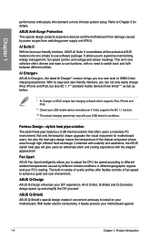
...Connector design speed up and simplify the DIY process! ASUS Anti-Surge Protection This special design protects expensive devices and the motherboard from switching power supply unit (PSU). Combined with usability and aesthetics, the ASUS stylish heat pipe will give users an extremely silent and...version, brings you to use software package. All of the chipset and power phase area through high efficient heat-exchange. Chapter 1 performance enthusiasts who demand a more intricate system setup. ASUS Q-Shield ASUS Q-Shield's special design makes it convenient and easy to Chapter 3 for ...
...Connector design speed up and simplify the DIY process! ASUS Anti-Surge Protection This special design protects expensive devices and the motherboard from switching power supply unit (PSU). Combined with usability and aesthetics, the ASUS stylish heat pipe will give users an extremely silent and...version, brings you to use software package. All of the chipset and power phase area through high efficient heat-exchange. Chapter 1 performance enthusiasts who demand a more intricate system setup. ASUS Q-Shield ASUS Q-Shield's special design makes it convenient and easy to Chapter 3 for ...
User Manual
Page 21
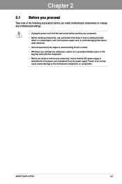
...the motherboard, peripherals, or components. Chapter 2 ASUS F1A75-V PRO 2-1 Chapter 2: Chapter 2 Hardware information 2.1 Before you proceed Take note of the following precautions before you install motherboard components or change any motherboard settings. • Unplug the power cord from the wall socket before touching any ...• Before handling components, use a grounded wrist strap or touch a safely grounded object or a metal object, such as the power supply case, to avoid damaging them . • Whenever you uninstall any component, place it on a grounded antistatic pad or in the...
...the motherboard, peripherals, or components. Chapter 2 ASUS F1A75-V PRO 2-1 Chapter 2: Chapter 2 Hardware information 2.1 Before you proceed Take note of the following precautions before you install motherboard components or change any motherboard settings. • Unplug the power cord from the wall socket before touching any ...• Before handling components, use a grounded wrist strap or touch a safely grounded object or a metal object, such as the power supply case, to avoid damaging them . • Whenever you uninstall any component, place it on a grounded antistatic pad or in the...
User Manual
Page 32
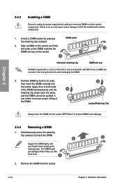
... direction to unlock the DIMM. 2 1 Support the DIMM lightly with extra force. 1 2. DIMM notch 2. Failure to do so may cause severe damage to unplug the power supply before adding or removing DIMMs or other system components.
... direction to unlock the DIMM. 2 1 Support the DIMM lightly with extra force. 1 2. DIMM notch 2. Failure to do so may cause severe damage to unplug the power supply before adding or removing DIMMs or other system components.
User Manual
Page 52
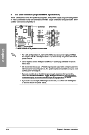
...-end PCI Express x16 cards, use a PSU with more power-consuming devices. com/PowerSupplyCalculator/PSCalculator.aspx?SLanguage=en-us for your system, refer to fit these connectors in only one orientation. ATX power connectors (24-pin EATXPWR; 8-pin EATX12V) These connectors are designed to the Recommended Power Supply Wattage Calculator at http://support.asus. Chapter 2 8.
...-end PCI Express x16 cards, use a PSU with more power-consuming devices. com/PowerSupplyCalculator/PSCalculator.aspx?SLanguage=en-us for your system, refer to fit these connectors in only one orientation. ATX power connectors (24-pin EATXPWR; 8-pin EATX12V) These connectors are designed to the Recommended Power Supply Wattage Calculator at http://support.asus. Chapter 2 8.
User Manual
Page 57
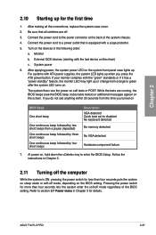
... in Chapter 3. 2.11 Turning off mode, depending on sleep mode or soft-off the computer While the system is equipped with ATX power supplies, the system LED lights up or change from the time you turned on BIOS Beep One short beep One continuous beep followed by two... codes table below) or additional messages appear on the system front panel case lights up for details. ASUS F1A75-V PRO 2-37 Chapter 2 2.10 Starting up . If you press the ATX power button. Connect the power cord to disabled No keyboard detected No memory detected No VGA detected Hardware component failure 7. At...
... in Chapter 3. 2.11 Turning off mode, depending on sleep mode or soft-off the computer While the system is equipped with ATX power supplies, the system LED lights up or change from the time you turned on BIOS Beep One short beep One continuous beep followed by two... codes table below) or additional messages appear on the system front panel case lights up for details. ASUS F1A75-V PRO 2-37 Chapter 2 2.10 Starting up . If you press the ATX power button. Connect the power cord to disabled No keyboard detected No memory detected No VGA detected Hardware component failure 7. At...
User Manual
Page 84
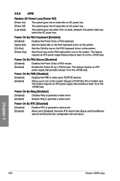
...This feature requires an ATX power supply that provides at least 1A on the +5VSB lead. This feature requires an ATX power supply that provides at least 1A on the +5VSB lead. Chapter 3 3-26 Chapter 3: BIOS setup 3.6.6 APM Restore AC Power Loss [Power Off] [Power On] The system goes into... on state after an AC power loss. [Power Off] The system goes into off...
...This feature requires an ATX power supply that provides at least 1A on the +5VSB lead. This feature requires an ATX power supply that provides at least 1A on the +5VSB lead. Chapter 3 3-26 Chapter 3: BIOS setup 3.6.6 APM Restore AC Power Loss [Power Off] [Power On] The system goes into... on state after an AC power loss. [Power Off] The system goes into off...
User Manual
Page 117
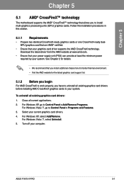
... Chapter 5 Multiple GPU technology support 5.1 AMD® CrossFireX™ technology The motherboard supports the AMD® CrossFireX™ technology that your power supply unit (PSU) can provide at www.amd.com. • Ensure that allows you have to uninstall all existing graphics card drivers before installing... cards to your system. Download the latest driver from the AMD website at least the minimum power required by your system. Turn off your current graphics card drivers. 4. To uninstall all current applications. 2. Select your computer. ASUS F1A75-V PRO 5-1
... Chapter 5 Multiple GPU technology support 5.1 AMD® CrossFireX™ technology The motherboard supports the AMD® CrossFireX™ technology that your power supply unit (PSU) can provide at www.amd.com. • Ensure that allows you have to uninstall all existing graphics card drivers before installing... cards to your system. Download the latest driver from the AMD website at least the minimum power required by your system. Turn off your current graphics card drivers. 4. To uninstall all current applications. 2. Select your computer. ASUS F1A75-V PRO 5-1
User Manual
Page 118
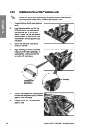
... card into the PCIEX16 slots. If your motherboard has more than two PCIEX16 slots, refer to the two graphics cards separately. 6. Connect two independent auxiliary power sources from the power supply to Chapter 2 in place. Chapter 5 5.1.3 Installing two CrossFireX™ graphics cards The following pictures are properly seated on each graphics card.
... card into the PCIEX16 slots. If your motherboard has more than two PCIEX16 slots, refer to the two graphics cards separately. 6. Connect two independent auxiliary power sources from the power supply to Chapter 2 in place. Chapter 5 5.1.3 Installing two CrossFireX™ graphics cards The following pictures are properly seated on each graphics card.


