
User Manual
Page 6
...5.3.8 ASUS Q-Fan Plus 5-31 5.3.9 ASUS AI Booster 2 5-32 5.3.10 CPU Level Up 5-33 5.4 RAID configurations 5-34 5.4.1 RAID definitions 5-34 5.4.2 NVIDIA® RAID configurations 5-35 5.5 Creating a RAID driver disk 5-42 5.5.1 Creating a RAID driver disk without entering the OS.... 5-42 5.5.2 Creating a RAID/SATA driver disk in Windows 5-42 Chapter 6: NVIDIA®technology support 6.1 NVIDIA® SLI™ technology 6-1 6.1.1 Requirements 6-1 6.1.2 Graphics card setup 6-2 6.1.3 Installing the device drivers 6-6 6.1.4 Enabling the NVIDIA® SLI™ technology in Windows®...
...5.3.8 ASUS Q-Fan Plus 5-31 5.3.9 ASUS AI Booster 2 5-32 5.3.10 CPU Level Up 5-33 5.4 RAID configurations 5-34 5.4.1 RAID definitions 5-34 5.4.2 NVIDIA® RAID configurations 5-35 5.5 Creating a RAID driver disk 5-42 5.5.1 Creating a RAID driver disk without entering the OS.... 5-42 5.5.2 Creating a RAID/SATA driver disk in Windows 5-42 Chapter 6: NVIDIA®technology support 6.1 NVIDIA® SLI™ technology 6-1 6.1.1 Requirements 6-1 6.1.2 Graphics card setup 6-2 6.1.3 Installing the device drivers 6-6 6.1.4 Enabling the NVIDIA® SLI™ technology in Windows®...

User Manual
Page 21
... a user-friendly BIOS update utility. ASUS Crosshair II Formula 1-5 It also provides stereo to experience crisp, clear sounds by restoring and compensating for clarity and quality of plugging in one complete module. See pages 4-4 and 4-47 for details. AI Audio 2 AI Audio 2 allows you to multi-channel sound field expansion for realistic front and rear environments and virtualized surround sound for added vocal clarity when used in stereo speakers...
... a user-friendly BIOS update utility. ASUS Crosshair II Formula 1-5 It also provides stereo to experience crisp, clear sounds by restoring and compensating for clarity and quality of plugging in one complete module. See pages 4-4 and 4-47 for details. AI Audio 2 AI Audio 2 allows you to multi-channel sound field expansion for realistic front and rear environments and virtualized surround sound for added vocal clarity when used in stereo speakers...
User Manual
Page 27
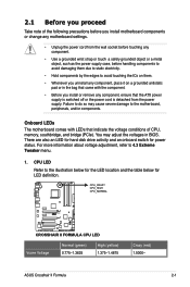
... the motherboard, peripherals, and/or components. CPU_CRAZY CPU_HIGH CPU_NORMAL CROSSHAIR II FORMULA ® RESET CROSSHAIR II FORMULA CPU LED Vcore Voltage Normal (green) 0.775-1.3625 High (yellow) 1.375-1.4875 Crazy (red) 1.5000- 2.1 Before you proceed Take note of CPU, memory, southbridge, and bridge (PCIe). For more information about voltage adjustment, refer to do so may adjust the voltages in the bag that came with LEDs that the ATX power supply is switched...
... the motherboard, peripherals, and/or components. CPU_CRAZY CPU_HIGH CPU_NORMAL CROSSHAIR II FORMULA ® RESET CROSSHAIR II FORMULA CPU LED Vcore Voltage Normal (green) 0.775-1.3625 High (yellow) 1.375-1.4875 Crazy (red) 1.5000- 2.1 Before you proceed Take note of CPU, memory, southbridge, and bridge (PCIe). For more information about voltage adjustment, refer to do so may adjust the voltages in the bag that came with LEDs that the ATX power supply is switched...

User Manual
Page 41
... DIMM sockets. 2.4.2 Memory configurations You may install a maximum of 2 GB DIMMs on each slot. 64-bit Windows® XP Professional x64 Edition Windows® Vista x64 Edition ASUS Crosshair II Formula 2-15 Populated Populated Sockets DIMM_A2 DIMM_B1 - - - The system maps the total size of 128 Mb chips. Any excess memory from the same vendor. • If you install four 1 GB memory modules, the system may install varying memory sizes in Channel A and Channel...
... DIMM sockets. 2.4.2 Memory configurations You may install a maximum of 2 GB DIMMs on each slot. 64-bit Windows® XP Professional x64 Edition Windows® Vista x64 Edition ASUS Crosshair II Formula 2-15 Populated Populated Sockets DIMM_A2 DIMM_B1 - - - The system maps the total size of 128 Mb chips. Any excess memory from the same vendor. • If you install four 1 GB memory modules, the system may install varying memory sizes in Channel A and Channel...

User Manual
Page 45
... or removing expansion cards. When using PCI cards on the slot. 5. ASUS Crosshair II Formula 2-19 Make sure to the table on the system and change the necessary BIOS settings, if any. The following sub‑sections describe the slots and the expansion cards that you removed earlier. 6. 2.5 Expansion slots In the future, you may cause you physical injury and damage motherboard components. 2.5.1 Installing an expansion card To install an expansion card: 1.
... or removing expansion cards. When using PCI cards on the slot. 5. ASUS Crosshair II Formula 2-19 Make sure to the table on the system and change the necessary BIOS settings, if any. The following sub‑sections describe the slots and the expansion cards that you removed earlier. 6. 2.5 Expansion slots In the future, you may cause you physical injury and damage motherboard components. 2.5.1 Installing an expansion card To install an expansion card: 1.

User Manual
Page 47
...black PCIe x1 slot. • Install a PCIe x1 device to a PCIe x1 slot prior to the figure below for the location of the three PCI Express x16 slots support PCIe 2.0 devices. Audio/PCI Express x1 slot PCI Express x 16 slot PCI Express x 1 slot PCI slot PCI Express x 16 slot PCI slot PCI Express x16 slot ASUS Crosshair II Formula 2-21 All of the slots. 2.5.5 PCI Express x1 slots This motherboard supports PCI Express x1 network cards, SCSI cards and other cards that support PCI Express x16 graphic cards complying with the PCI Express specifications. Refer to a PCIe x16 slot. 2.5.6 PCI...
...black PCIe x1 slot. • Install a PCIe x1 device to a PCIe x1 slot prior to the figure below for the location of the three PCI Express x16 slots support PCIe 2.0 devices. Audio/PCI Express x1 slot PCI Express x 16 slot PCI Express x 1 slot PCI slot PCI Express x 16 slot PCI slot PCI Express x16 slot ASUS Crosshair II Formula 2-21 All of the slots. 2.5.5 PCI Express x1 slots This motherboard supports PCI Express x1 network cards, SCSI cards and other cards that support PCI Express x16 graphic cards complying with the PCI Express specifications. Refer to a PCIe x16 slot. 2.5.6 PCI...

User Manual
Page 55
2.8.2 Internal connectors 1. IDE connector (40-1 pin PRI_IDE) The onboard IDE connector is for Ultra DMA 133/100/66 IDE devices. PRI_IDE NOTE:Orient the red markings on the IDE ribbon cable to match the covered hole on the Ultra DMA cable connector. CROSSHAIR II FORMULA ® PIN1 RESET CROSSHAIR II FORMULA IDE connector ASUS Crosshair II Formula 2-29 If any device jumper is removed to PIN 1. Single device Two devices Drive jumper setting Cable-Select or Master Cable-Select Master Slave Mode of the following modes to configure your device. Connect the blue connector to...
2.8.2 Internal connectors 1. IDE connector (40-1 pin PRI_IDE) The onboard IDE connector is for Ultra DMA 133/100/66 IDE devices. PRI_IDE NOTE:Orient the red markings on the IDE ribbon cable to match the covered hole on the Ultra DMA cable connector. CROSSHAIR II FORMULA ® PIN1 RESET CROSSHAIR II FORMULA IDE connector ASUS Crosshair II Formula 2-29 If any device jumper is removed to PIN 1. Single device Two devices Drive jumper setting Cable-Select or Master Cable-Select Master Slave Mode of the following modes to configure your device. Connect the blue connector to...
User Manual
Page 56
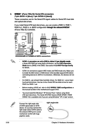
...; a Serial ATA RAID set using these connectors, set , refer to SATA device. Make sure to install the AHCI driver or RAID driver in the motherboard support DVD. • You must install the Windows® XP Service Pack 1 before connecting devices to [RAID] in the BIOS. The Serial ATA RAID feature (RAID 0/RAID 1/RAID 5/RAID 10) is available only if you may connect the right-angle side of SATA signal cable to 5.4.2 NVIDIA® RAID configurations or the manual bundled in the bundled support DVD before using Serial ATA hard disk drives. Or...
...; a Serial ATA RAID set using these connectors, set , refer to SATA device. Make sure to install the AHCI driver or RAID driver in the motherboard support DVD. • You must install the Windows® XP Service Pack 1 before connecting devices to [RAID] in the BIOS. The Serial ATA RAID feature (RAID 0/RAID 1/RAID 5/RAID 10) is available only if you may connect the right-angle side of SATA signal cable to 5.4.2 NVIDIA® RAID configurations or the manual bundled in the bundled support DVD before using Serial ATA hard disk drives. Or...

User Manual
Page 57
... the USB connector onboard. Pin 5 on the floppy ribbon cable to the USB connectors. These USB connectors comply with USB 2.0 specification that supports up to prevent incorrect cable connection when using a FDD cable with a covered Pin 5. USB connectors (10-1 pin USB 78; CROSSHAIR II FORMULA Floppy disk drive connector 4. USB1112) These connectors are for the provided floppy disk drive (FDD) signal cable. You can connect the USB cable to ASUS Q-Connector (USB, blue) first, and then install the Q-Connector (USB) to a slot opening at the back of the system chassis.
... the USB connector onboard. Pin 5 on the floppy ribbon cable to the USB connectors. These USB connectors comply with USB 2.0 specification that supports up to prevent incorrect cable connection when using a FDD cable with a covered Pin 5. USB connectors (10-1 pin USB 78; CROSSHAIR II FORMULA Floppy disk drive connector 4. USB1112) These connectors are for the provided floppy disk drive (FDD) signal cable. You can connect the USB cable to ASUS Q-Connector (USB, blue) first, and then install the Q-Connector (USB) to a slot opening at the back of the system chassis.

User Manual
Page 59
... plug the chassis fan cable to the fan connectors. CPU, chassis, and optional fan connectors (4-pin CPU_FAN, 3-pin CHA_FAN1-3, 3-pin PWR_FAN, 3‑pin OPT_FAN1-3) The fan connectors support cooling fans of 350 mA-1000 mA (24 W max.) or a total of the connector. Insufficient air flow inside the system may damage the motherboard components. ASUS Crosshair II Formula 2-33 7. DO NOT place jumper caps on the motherboard, making sure that you install multiple VGA cards, we recommend that the black wire of each cable...
... plug the chassis fan cable to the fan connectors. CPU, chassis, and optional fan connectors (4-pin CPU_FAN, 3-pin CHA_FAN1-3, 3-pin PWR_FAN, 3‑pin OPT_FAN1-3) The fan connectors support cooling fans of 350 mA-1000 mA (24 W max.) or a total of the connector. Insufficient air flow inside the system may damage the motherboard components. ASUS Crosshair II Formula 2-33 7. DO NOT place jumper caps on the motherboard, making sure that you install multiple VGA cards, we recommend that the black wire of each cable...
User Manual
Page 73
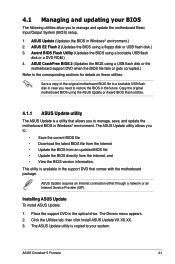
.... ASUS Update requires an Internet connection either through a network or an Internet Service Provider (ISP). ASUS Crosshair II Formula 4-1 The ASUS Update utility is a utility that comes with the motherboard package. Installing ASUS Update To install ASUS Update: 1. 4.1 Managing and updating your system. ASUS EZ Flash 2 (Updates the BIOS using a bootable USB flash disk or a DVD ROM.) 4. Award BIOS Flash Utility (Updates the BIOS using a floppy disk or USB flash disk.) 3. Copy the original motherboard BIOS using a USB flash disk or the motherboard support DVD when the BIOS file...
.... ASUS Update requires an Internet connection either through a network or an Internet Service Provider (ISP). ASUS Crosshair II Formula 4-1 The ASUS Update utility is a utility that comes with the motherboard package. Installing ASUS Update To install ASUS Update: 1. 4.1 Managing and updating your system. ASUS EZ Flash 2 (Updates the BIOS using a bootable USB flash disk or a DVD ROM.) 4. Award BIOS Flash Utility (Updates the BIOS using a floppy disk or USB flash disk.) 3. Copy the original motherboard BIOS using a USB flash disk or the motherboard support DVD when the BIOS file...

User Manual
Page 81
... chassis. You can also restart by pressing the reset button on your BIOS." If you wish to enter Setup after changing any BIOS settings, load the default settings to download the latest BIOS file for reference purposes only, and may not exactly match what you to reconfigure your system, or prompted to ensure optimum performance. ASUS Crosshair II Formula 4-9 Use the BIOS Setup program when you are for this motherboard. 4.2 BIOS setup program This motherboard supports a programmable Serial...
... chassis. You can also restart by pressing the reset button on your BIOS." If you wish to enter Setup after changing any BIOS settings, load the default settings to download the latest BIOS file for reference purposes only, and may not exactly match what you to reconfigure your system, or prompted to ensure optimum performance. ASUS Crosshair II Formula 4-9 Use the BIOS Setup program when you are for this motherboard. 4.2 BIOS setup program This motherboard supports a programmable Serial...

User Manual
Page 92
...] CPU Configuration Phoenix-AwardBIOS CMOS Setup Utility Extreme Tweaker Overclocking Select Menu CPU Type AMD Phenom(tm)8400 Triple-Core Processor CPU Speed 2100MHz Cache RAM(L2) 512K x3 Cache RAM(L3) 2048K AMD Virtualization [Enabled] AMD Live! [Disabled] AMD Cool'n'Quiet Function [Disabled] Cache Mapping Cycle [Auto] CPU Instruction Fetch [Auto] CPU DownCore Control [Disabled] Item Specific Help Enabling processor virtualization allows hardware facilitated capabilities for the safe mode. technology. Configuration options: [Auto] [Disabled...
...] CPU Configuration Phoenix-AwardBIOS CMOS Setup Utility Extreme Tweaker Overclocking Select Menu CPU Type AMD Phenom(tm)8400 Triple-Core Processor CPU Speed 2100MHz Cache RAM(L2) 512K x3 Cache RAM(L3) 2048K AMD Virtualization [Enabled] AMD Live! [Disabled] AMD Cool'n'Quiet Function [Disabled] Cache Mapping Cycle [Auto] CPU Instruction Fetch [Auto] CPU DownCore Control [Disabled] Item Specific Help Enabling processor virtualization allows hardware facilitated capabilities for the safe mode. technology. Configuration options: [Auto] [Disabled...

User Manual
Page 102
...] [Enabled] Onboard LAN/LAN2 Boot ROM [Disabled] Allows you to enable or disable the onchip USB controller. Configuration options: [Enabled] [Disabled] Onboard 1394 [Enabled] Allows you to enable or disable the HDMI audio function. USB Controller [Enabled] Allows you to display the configuration options. Select an item then press to enable or disable the USB 2.0 controller. Phoenix-AwardBIOS CMOS Setup Utility Advanced USB Configuration Select Menu USB Controller [Enabled] USB 2.0 Controller [Enabled] USB Legacy support [Enabled] Item Specific Help Enable or Disable USB...
...] [Enabled] Onboard LAN/LAN2 Boot ROM [Disabled] Allows you to enable or disable the onchip USB controller. Configuration options: [Enabled] [Disabled] Onboard 1394 [Enabled] Allows you to enable or disable the HDMI audio function. USB Controller [Enabled] Allows you to display the configuration options. Select an item then press to enable or disable the USB 2.0 controller. Phoenix-AwardBIOS CMOS Setup Utility Advanced USB Configuration Select Menu USB Controller [Enabled] USB 2.0 Controller [Enabled] USB Legacy support [Enabled] Item Specific Help Enable or Disable USB...
User Manual
Page 104
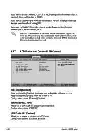
... 4: BIOS setup If you to use the Advanced Host Controller Interface (AHCI), set this item is on /off the onboard Voltiminder LED. Use SATA 1-4 connectors for IDE mode. Make sure to install the AHCI driver or RAID driver in the bundled support DVD before connecting devices to [Enabled], the box labeled as Parallel ATA physical storage devices, keep the default setting [IDE]. Configuration options: [ON] [OFF] LCD Poster Off [Enabled] Allows you want the Serial ATA hard disk drives to use the Serial ATA hard disk drives as Republic of Gamers on...
... 4: BIOS setup If you to use the Advanced Host Controller Interface (AHCI), set this item is on /off the onboard Voltiminder LED. Use SATA 1-4 connectors for IDE mode. Make sure to install the AHCI driver or RAID driver in the bundled support DVD before connecting devices to [Enabled], the box labeled as Parallel ATA physical storage devices, keep the default setting [IDE]. Configuration options: [ON] [OFF] LCD Poster Off [Enabled] Allows you want the Serial ATA hard disk drives to use the Serial ATA hard disk drives as Republic of Gamers on...

User Manual
Page 112
... Value Enter: Select SubMenu F5: Setup Defaults F10: Save and Exit 4.7.1 Boot Device Priority Main Phoenix-AwardBIOS CMOS Setup Utility Extreme Tweaker Advanced Power Boot Tools Boot Device Priority Exit Select Menu 1st Boot Device 2nd Boot Device 3rd Boot Device 4th Boot Device [Removable] [Hard Disk] [CDROM] [Disabled] Item Specific Help Select Your Boot Device Priority 1st ~ 4th Boot Device [Removable] These items specify the boot device priority sequence from the available devices. Select an item then press to set this item to change the system boot options. CPU Fan Speed...
... Value Enter: Select SubMenu F5: Setup Defaults F10: Save and Exit 4.7.1 Boot Device Priority Main Phoenix-AwardBIOS CMOS Setup Utility Extreme Tweaker Advanced Power Boot Tools Boot Device Priority Exit Select Menu 1st Boot Device 2nd Boot Device 3rd Boot Device 4th Boot Device [Removable] [Hard Disk] [CDROM] [Disabled] Item Specific Help Select Your Boot Device Priority 1st ~ 4th Boot Device [Removable] These items specify the boot device priority sequence from the available devices. Select an item then press to set this item to change the system boot options. CPU Fan Speed...
User Manual
Page 156
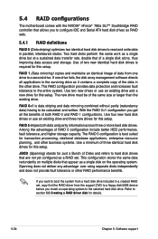
Two hard disks perform the same work as a RAID set , copy first the RAID driver from the support DVD to a floppy disk/USB device before you get all applications to the surviving drive as a single disk on multiple disks that appear as it contains a complete copy of a single disk alone, thus improving data access and storage. This RAID configuration provides data protection and increases fault tolerance to a second drive. RAID 0+1 is data striping and...
Two hard disks perform the same work as a RAID set , copy first the RAID driver from the support DVD to a floppy disk/USB device before you get all applications to the surviving drive as a single disk on multiple disks that appear as it contains a complete copy of a single disk alone, thus improving data access and storage. This RAID configuration provides data protection and increases fault tolerance to a second drive. RAID 0+1 is data striping and...
User Manual
Page 157
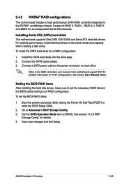
...Manuals menu. ASUS Crosshair II Formula 5-35 To install the SATA hard disks for detailed information on each drive. Boot the system and press during the Power-On Self-Test (POST) to [RAID]. It supports RAID 0, RAID 1, RAID 0+1, RAID 5 and JBOD for details. 4. Connect the SATA signal cables. 3. For optimal performance, install identical drives of the same model and capacity when creating a disk array. Set the SATA Operation Mode item to enter the BIOS Setup Utility. 2. 5.4.2 NVIDIA® RAID configurations The motherboard includes a high performance SATA RAID controller...
...Manuals menu. ASUS Crosshair II Formula 5-35 To install the SATA hard disks for detailed information on each drive. Boot the system and press during the Power-On Self-Test (POST) to [RAID]. It supports RAID 0, RAID 1, RAID 0+1, RAID 5 and JBOD for details. 4. Connect the SATA signal cables. 3. For optimal performance, install identical drives of the same model and capacity when creating a disk array. Set the SATA Operation Mode item to enter the BIOS Setup Utility. 2. 5.4.2 NVIDIA® RAID configurations The motherboard includes a high performance SATA RAID controller...

User Manual
Page 164
...Place the motherboard support DVD into the floppy drive then press . 9. Write-protect the floppy disk to enter the BIOS setup utility. 3. To install the RAID driver in Windows®: 1. Press any key when the system prompts "Press any key to complete the process. Start Windows®. 2. Insert a floppy disk/USB device into the floppy disk drive. 3. Follow succeeding screen instructions to complete the process. 5.5.2 Creating a RAID/SATA driver disk in Windows® To create a RAID driver disk in Windows® XP: 1. Follow succeeding screen instructions to boot from the...
...Place the motherboard support DVD into the floppy drive then press . 9. Write-protect the floppy disk to enter the BIOS setup utility. 3. To install the RAID driver in Windows®: 1. Press any key when the system prompts "Press any key to complete the process. Start Windows®. 2. Insert a floppy disk/USB device into the floppy disk drive. 3. Follow succeeding screen instructions to complete the process. 5.5.2 Creating a RAID/SATA driver disk in Windows® To create a RAID driver disk in Windows® XP: 1. Follow succeeding screen instructions to boot from the...

User Manual
Page 183
Clear CMOS error flag 1. Enable keyboard interface. 1. Program chipset default values into the run time area in CMOS circuitry. Initialize clock generator. Example: onboard IDE controller. 4. ASUS Crosshair II Formula A-1 Reset keyboard for 0-640K memory address. 2. Detect CPU information including brand, type and CPU level (586 or 686). Program CPU internal MTRR (Pentium class CPU) for Super I /O chips. 2. Initialize multi-language 2. Initialize IO devices. Initialize 8042 self-test 1. Auto detect ports for Pentium class CPU. 3. Reset keyboard. ...
Clear CMOS error flag 1. Enable keyboard interface. 1. Program chipset default values into the run time area in CMOS circuitry. Initialize clock generator. Example: onboard IDE controller. 4. ASUS Crosshair II Formula A-1 Reset keyboard for 0-640K memory address. 2. Detect CPU information including brand, type and CPU level (586 or 686). Program CPU internal MTRR (Pentium class CPU) for Super I /O chips. 2. Initialize multi-language 2. Initialize IO devices. Initialize 8042 self-test 1. Auto detect ports for Pentium class CPU. 3. Reset keyboard. ...


