
User Manual
Page 31
Reading flash ..... ok A:\> 當 BIOS DOS 31 exe 2 DOS afudos /o[filename filename A:\>afudos /oOLDBIOS1.rom 3. 按下 afudos /oOLDBIOS1.rom AMI Firmware Update Utility - Version 1.19(ASUS V2.07(03.11.24BB)) Copyright (C) 2002 American Megatrends, Inc. All rights reserved. done Write to file...... BIOS 2.1 使用 AFUDOS BIOS AFUDOS DOS BIOS BIOS 程式。AFUDOS BIOS BIOS BIOS 程式 BIOS 程式。 1.2MB BIOS 1 AFUDOS 程式(afudos.
Reading flash ..... ok A:\> 當 BIOS DOS 31 exe 2 DOS afudos /o[filename filename A:\>afudos /oOLDBIOS1.rom 3. 按下 afudos /oOLDBIOS1.rom AMI Firmware Update Utility - Version 1.19(ASUS V2.07(03.11.24BB)) Copyright (C) 2002 American Megatrends, Inc. All rights reserved. done Write to file...... BIOS 2.1 使用 AFUDOS BIOS AFUDOS DOS BIOS BIOS 程式。AFUDOS BIOS BIOS BIOS 程式 BIOS 程式。 1.2MB BIOS 1 AFUDOS 程式(afudos.

User Manual
Page 32
...(03.11.24BB)) Copyright (C) 2002 American Megatrends, Inc. All rights reserved. done Advance Check ...... 更新 BIOS 程式 AFUDOS BIOS 程式。 1 tw.asus.com BIOS 片中。 BIOS BIOS 2. 將 AFUDOS.EXE BIOS 3 DOS afudos /i[filename filename BIOS 程式。 A:\>afudos /iP5B-VM DO.ROM 4. WARNING!! Erasing flash ...... Do not turn off power...
...(03.11.24BB)) Copyright (C) 2002 American Megatrends, Inc. All rights reserved. done Advance Check ...... 更新 BIOS 程式 AFUDOS BIOS 程式。 1 tw.asus.com BIOS 片中。 BIOS BIOS 2. 將 AFUDOS.EXE BIOS 3 DOS afudos /i[filename filename BIOS 程式。 A:\>afudos /iP5B-VM DO.ROM 4. WARNING!! Erasing flash ...... Do not turn off power...

User Manual
Page 33
... 程式(AWDFLASH.EXE BIOS AwardBIOS Flash BIOS 程式。 1 http://tw.asus.com BIOS M2N-VM HDMI.bin FAT 32/16 格式的 USB BIOS 2 CD/DVD AwardBIOS Flash BIOS 3 DOS 4. 當 A BIOS 檔案與 AwardBIOS Flash 5 A awdflash 並按下 鍵。 AwardBIOS Flash Utility for ASUS V1.14 (C) Phoenix Technologies Ltd...
... 程式(AWDFLASH.EXE BIOS AwardBIOS Flash BIOS 程式。 1 http://tw.asus.com BIOS M2N-VM HDMI.bin FAT 32/16 格式的 USB BIOS 2 CD/DVD AwardBIOS Flash BIOS 3 DOS 4. 當 A BIOS 檔案與 AwardBIOS Flash 5 A awdflash 並按下 鍵。 AwardBIOS Flash Utility for ASUS V1.14 (C) Phoenix Technologies Ltd...

User Manual
Page 34
... Flash Type - OFE00 OK Write OK No Update Write Fail Warning: Don't Turn Off Power Or Reset System! 在更新 BIOS 9 Flash Complete BIOS F1 AwardBIOS Flash Utility for ASUS V1.14 (C) Phoenix Technologies Ltd. All Rights Reserved For C51PV-MCP51-M2A-VM HDMI-00 DATE:04/13/2006 Flash Type - PMC... Program: M2A-VM HDMI.bin Programming Flash Memory - PMC Pm49FL004T LPC/FWH File Name to Continue Write OK F1 Reset No Update Write Fail 34 BIOS 7 BIOS N BIOS 8 BIOS BIOS AwardBIOS Flash Utility for ASUS V1.14 (C) Phoenix Technologies Ltd.
... Flash Type - OFE00 OK Write OK No Update Write Fail Warning: Don't Turn Off Power Or Reset System! 在更新 BIOS 9 Flash Complete BIOS F1 AwardBIOS Flash Utility for ASUS V1.14 (C) Phoenix Technologies Ltd. All Rights Reserved For C51PV-MCP51-M2A-VM HDMI-00 DATE:04/13/2006 Flash Type - PMC... Program: M2A-VM HDMI.bin Programming Flash Memory - PMC Pm49FL004T LPC/FWH File Name to Continue Write OK F1 Reset No Update Write Fail 34 BIOS 7 BIOS N BIOS 8 BIOS BIOS AwardBIOS Flash Utility for ASUS V1.14 (C) Phoenix Technologies Ltd.

User Manual
Page 4
... the computer 3-2 3.2.1 Using the OS shut down function 3-2 3.2.2 Using the dual function power switch 3-2 Chapter 4: BIOS setup 4.1 Managing and updating your BIOS 4-1 4.1.1 ASUS Update utility 4-1 4.1.2 ASUS EZ Flash 2 utility 4-4 4.1.3 Updating the BIOS 4-5 4.1.4 Saving the current BIOS file 4-7 4.1.5 ASUS CrashFree BIOS 2 utility 4-8 4.2 BIOS setup program 4-9 4.2.1 BIOS menu screen 4-10 4.2.2 Menu bar 4-10 4.2.3 Legend bar 4-11 4.2.4 Menu items 4-11 4.2.5 Sub-menu items...
... the computer 3-2 3.2.1 Using the OS shut down function 3-2 3.2.2 Using the dual function power switch 3-2 Chapter 4: BIOS setup 4.1 Managing and updating your BIOS 4-1 4.1.1 ASUS Update utility 4-1 4.1.2 ASUS EZ Flash 2 utility 4-4 4.1.3 Updating the BIOS 4-5 4.1.4 Saving the current BIOS file 4-7 4.1.5 ASUS CrashFree BIOS 2 utility 4-8 4.2 BIOS setup program 4-9 4.2.1 BIOS menu screen 4-10 4.2.2 Menu bar 4-10 4.2.3 Legend bar 4-11 4.2.4 Menu items 4-11 4.2.5 Sub-menu items...

User Manual
Page 10
...through the BIOS Setup menus. These documents are also provided. • Chapter 5: Software support This chapter describes the contents of the switches, jumpers, and connectors on ASUS hardware and software products. It includes description of the support DVD that comes with the motherboard package.... table The Appendix includes the debug code table for product and software updates. 1. Detailed descriptions of the BIOS parameters are not part of the motherboard and the new technology it supports. • Chapter 2: Hardware information This chapter lists the hardware setup procedures...
...through the BIOS Setup menus. These documents are also provided. • Chapter 5: Software support This chapter describes the contents of the switches, jumpers, and connectors on ASUS hardware and software products. It includes description of the support DVD that comes with the motherboard package.... table The Appendix includes the debug code table for product and software updates. 1. Detailed descriptions of the BIOS parameters are not part of the motherboard and the new technology it supports. • Chapter 2: Hardware information This chapter lists the hardware setup procedures...
User Manual
Page 13
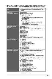
Crosshair II Formula specifications summary USB ASUS ROG Overclocking Features ASUS ROG Special Features Back Panel I/O Ports Internal I/O Connectors 12 x USB 2.0 ports (6 ports at midboard, 6 ports at rear) Q-Connector ASUS Q-Fan Plus ASUS EZ Flash 2 ASUS Q-Shield ASUS MyLogo 3™ Stack Cool 2 100% All High-quality Conductive Polymer ...(continued on the next page) xiii CPU Level Up - AI Booster Utility - Voltiminder LED - ASUS C.P.R. (CPU Parameter Recall) LCD Poster ROG BIOS Wallpaper Onboard Switches: Power / Reset / Clr CMOS (at back panel) Extreme Tweaker New 8+2 phase...
Crosshair II Formula specifications summary USB ASUS ROG Overclocking Features ASUS ROG Special Features Back Panel I/O Ports Internal I/O Connectors 12 x USB 2.0 ports (6 ports at midboard, 6 ports at rear) Q-Connector ASUS Q-Fan Plus ASUS EZ Flash 2 ASUS Q-Shield ASUS MyLogo 3™ Stack Cool 2 100% All High-quality Conductive Polymer ...(continued on the next page) xiii CPU Level Up - AI Booster Utility - Voltiminder LED - ASUS C.P.R. (CPU Parameter Recall) LCD Poster ROG BIOS Wallpaper Onboard Switches: Power / Reset / Clr CMOS (at back panel) Extreme Tweaker New 8+2 phase...

User Manual
Page 14
Crosshair II Formula specifications summary BIOS Features Manageability Accessories Software Form Factor 8 MB AWARD BIOS, PnP, DMI2.0, WfM2.0, ��S�M��B��IO��S�2��.4�,�A��C�P&#...;I�O�S� WOL by PME, WOR by PME, Chassis Intrusion, PXE 3-Way SLI bridge ASUS SLI bridge LCD Poster ASUS Optional Fan SupremeFX II Audio Card HDMI/DVI adapter 3 in 1 ASUS Q-connector kit UltraDMA 133/100/66 cable Floppy disk drive cable Serial ATA cables Serial ATA power cables...
Crosshair II Formula specifications summary BIOS Features Manageability Accessories Software Form Factor 8 MB AWARD BIOS, PnP, DMI2.0, WfM2.0, ��S�M��B��IO��S�2��.4�,�A��C�P&#...;I�O�S� WOL by PME, WOR by PME, Chassis Intrusion, PXE 3-Way SLI bridge ASUS SLI bridge LCD Poster ASUS Optional Fan SupremeFX II Audio Card HDMI/DVI adapter 3 in 1 ASUS Q-connector kit UltraDMA 133/100/66 cable Floppy disk drive cable Serial ATA cables Serial ATA power cables...

User Manual
Page 19
... in 3D environment during POST. See page 4-45 for each parameter. Simply reboot the system, and the BIOS automatically restores the CPU default settings for details. ASUS Crosshair II Formula 1-3 Profile Overclock immediately with OC profile presets. C.P.R. (CPU Parameter Recall) When the system hangs due to...need to open the system chassis to spot enemies in an ever friendly and flexible external display. See page 2-25 for gamers to clear CMOS data. Much more than simple frequency settings, this profile contains comprehensive and detailed tuning to frequency, voltages, ...
... in 3D environment during POST. See page 4-45 for each parameter. Simply reboot the system, and the BIOS automatically restores the CPU default settings for details. ASUS Crosshair II Formula 1-3 Profile Overclock immediately with OC profile presets. C.P.R. (CPU Parameter Recall) When the system hangs due to...need to open the system chassis to spot enemies in an ever friendly and flexible external display. See page 2-25 for gamers to clear CMOS data. Much more than simple frequency settings, this profile contains comprehensive and detailed tuning to frequency, voltages, ...
User Manual
Page 20
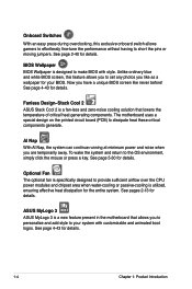
... page 2-40 for details. Fanless Design-Stack Cool 2 ASUS Stack Cool 2 is a new feature present in the motherboard that lowers the temperature of critical heat generating components. See page 4-43 for details. Unlike ordinary blue and white BIOS screen, this exclusive onboard switch allows gamers to effortlessly fine-tune the performance without having to...
... page 2-40 for details. Fanless Design-Stack Cool 2 ASUS Stack Cool 2 is a new feature present in the motherboard that lowers the temperature of critical heat generating components. See page 4-43 for details. Unlike ordinary blue and white BIOS screen, this exclusive onboard switch allows gamers to effortlessly fine-tune the performance without having to...

User Manual
Page 21
... to install computer components, update the BIOS or back up your favorite settings. ASUS Crosshair II Formula 1-5 This unique adapter eliminates the trouble of compressed audio in a few clicks without preparing an additional floppy diskette or using a USB flash disk without the usual "fingers"- You can update your motherboard against static electricity and shields it convenient...
... to install computer components, update the BIOS or back up your favorite settings. ASUS Crosshair II Formula 1-5 This unique adapter eliminates the trouble of compressed audio in a few clicks without preparing an additional floppy diskette or using a USB flash disk without the usual "fingers"- You can update your motherboard against static electricity and shields it convenient...
User Manual
Page 27
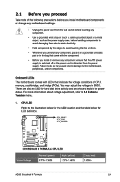
Onboard LEDs The motherboard comes with the component. • Before you uninstall any component, place it on a grounded antistatic pad or in BIOS. There are also an LED for hard disk drive activity and an onboard switch for ... from the power supply. CPU_CRAZY CPU_HIGH CPU_NORMAL CROSSHAIR II FORMULA ® RESET CROSSHAIR II FORMULA CPU LED Vcore Voltage Normal (green) 0.775-1.3625 High (yellow) 1.375-1.4875 Crazy (red) 1.5000- ASUS Crosshair II Formula 2-1 For more information about voltage adjustment, refer to the motherboard, peripherals, and/or components. You may cause...
Onboard LEDs The motherboard comes with the component. • Before you uninstall any component, place it on a grounded antistatic pad or in BIOS. There are also an LED for hard disk drive activity and an onboard switch for ... from the power supply. CPU_CRAZY CPU_HIGH CPU_NORMAL CROSSHAIR II FORMULA ® RESET CROSSHAIR II FORMULA CPU LED Vcore Voltage Normal (green) 0.775-1.3625 High (yellow) 1.375-1.4875 Crazy (red) 1.5000- ASUS Crosshair II Formula 2-1 For more information about voltage adjustment, refer to the motherboard, peripherals, and/or components. You may cause...

User Manual
Page 28
...2.52- 3. Refer to the illustration below for the LED location and the table below for LED definition. CROSSHAIR II FORMULA ® SB_CRAZY SB_HIGH SB_NORMAL BR_CRAZY BR_HIGH BR_NORMAL RESET CROSSHAIR II FORMULA Southbridge/Bridge(PCIe) LED SB Voltage HT Voltage BR Voltage Normal (green) 1.10-1.30 1.20-1.40 1....20-1.40 High (yellow) 1.32-1.50 1.42-1.60 1.42-1.60 Crazy (red) 1.52- 1.62- 1.62- 2-2 Chapter 2: Hardware information Memory LED Refer to display in BIOS...
...2.52- 3. Refer to the illustration below for the LED location and the table below for LED definition. CROSSHAIR II FORMULA ® SB_CRAZY SB_HIGH SB_NORMAL BR_CRAZY BR_HIGH BR_NORMAL RESET CROSSHAIR II FORMULA Southbridge/Bridge(PCIe) LED SB Voltage HT Voltage BR Voltage Normal (green) 1.10-1.30 1.20-1.40 1....20-1.40 High (yellow) 1.32-1.50 1.42-1.60 1.42-1.60 Crazy (red) 1.52- 1.62- 1.62- 2-2 Chapter 2: Hardware information Memory LED Refer to display in BIOS...

User Manual
Page 31
2.2.3 Motherboard layout CLR_CMOS CHA_FAN1 CHA_FAN2 LCD_CON KB_USB56 EATX12V 24.5cm (9.6in) CPU_CRAZY CPU_HIGH CPU_NORMAL CPU_FAN SPDIF_OUT SPDIF_O12 PWR_FAN SOCKET AM2+/AM2 DDR DIMM_A1 (64bit, ... NVIDIA® nForce® 200 HD_LED Lithium Cell CMOS Power CLR_SW Super I/O CHASSIS SATA56 SATA34 SATA12 VIA VT6308P IE1394_2 PCI2 USB1112 FLOPPY BIOS RESET USB78 CHA_FAN3 USB910 PANEL Refer to 2.8 Connectors for more information about rear panel connectors and internal connectors. 2.2.4 Audio card layout SUPREMEFX II Listen with Absolute HD ASUS Crosshair II Formula 2-5
2.2.3 Motherboard layout CLR_CMOS CHA_FAN1 CHA_FAN2 LCD_CON KB_USB56 EATX12V 24.5cm (9.6in) CPU_CRAZY CPU_HIGH CPU_NORMAL CPU_FAN SPDIF_OUT SPDIF_O12 PWR_FAN SOCKET AM2+/AM2 DDR DIMM_A1 (64bit, ... NVIDIA® nForce® 200 HD_LED Lithium Cell CMOS Power CLR_SW Super I/O CHASSIS SATA56 SATA34 SATA12 VIA VT6308P IE1394_2 PCI2 USB1112 FLOPPY BIOS RESET USB78 CHA_FAN3 USB910 PANEL Refer to 2.8 Connectors for more information about rear panel connectors and internal connectors. 2.2.4 Audio card layout SUPREMEFX II Listen with Absolute HD ASUS Crosshair II Formula 2-5

User Manual
Page 45
... is already installed in a chassis). 3. ASUS Crosshair II Formula 2-19 2.5 Expansion slots In the future, you may cause you removed earlier. 6. See Chapter 4 for later use . Remove the system unit cover (if your motherboard is completely seated on BIOS setup. 2. Remove the bracket opposite the ... so may need IRQ assignments. Failure to the card. Align the card connector with the screw you physical injury and damage motherboard components. 2.5.1 Installing an expansion card To install an expansion card: 1. Otherwise, conflicts will arise between the two PCI groups...
... is already installed in a chassis). 3. ASUS Crosshair II Formula 2-19 2.5 Expansion slots In the future, you may cause you removed earlier. 6. See Chapter 4 for later use . Remove the system unit cover (if your motherboard is completely seated on BIOS setup. 2. Remove the bracket opposite the ... so may need IRQ assignments. Failure to the card. Align the card connector with the screw you physical injury and damage motherboard components. 2.5.1 Installing an expansion card To install an expansion card: 1. Otherwise, conflicts will arise between the two PCI groups...

User Manual
Page 49
... the Disable position, but the shutdwon function in S0 mode (DOS mode) still works. • Make sure to re-enter your previous BIOS settings after you to CPU overclocking. ASUS Crosshair II Formula 2-23 With the C.P.R. (CPU Parameter Recall) feature, shut down the clr CMOS switch will not function if the jumper cap on the...
... the Disable position, but the shutdwon function in S0 mode (DOS mode) still works. • Make sure to re-enter your previous BIOS settings after you to CPU overclocking. ASUS Crosshair II Formula 2-23 With the C.P.R. (CPU Parameter Recall) feature, shut down the clr CMOS switch will not function if the jumper cap on the...
User Manual
Page 56
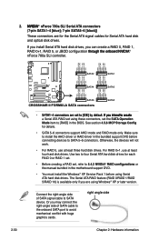
...GND RSATA_TXN4 RSATA_TXP4 GND CROSSHAIR II FORMULA ® SATA4 SATA3 GND RSATA_RXN5 RSATA_TXP5 GND RSATA_TXN5 RSATA_TXP5 GND GND RSATA_RXN6 RSATA_TXP6 GND RSATA_TXN6 RSATA_TXP6 GND SATA6 RESET CROSSHAIR II FORMULA SATA connectors SATA5 S&#... or RAID driver in the bundled support DVD before connecting devices to [RAID] in the motherboard support DVD. • You must install the Windows® XP Service Pack 1 before...the onboard SATA port to 5.4.2 NVIDIA® RAID configurations or the manual bundled in the BIOS. Use two to four Serial ATA hard disk drives for each RAID 0 or RAID 1...
...GND RSATA_TXN4 RSATA_TXP4 GND CROSSHAIR II FORMULA ® SATA4 SATA3 GND RSATA_RXN5 RSATA_TXP5 GND RSATA_TXN5 RSATA_TXP5 GND GND RSATA_RXN6 RSATA_TXP6 GND RSATA_TXN6 RSATA_TXP6 GND SATA6 RESET CROSSHAIR II FORMULA SATA connectors SATA5 S&#... or RAID driver in the bundled support DVD before connecting devices to [RAID] in the motherboard support DVD. • You must install the Windows® XP Service Pack 1 before...the onboard SATA port to 5.4.2 NVIDIA® RAID configurations or the manual bundled in the BIOS. Use two to four Serial ATA hard disk drives for each RAID 0 or RAID 1...

User Manual
Page 58
Doing so will damage the motherboard! TPA2GND TPB2+12V GND TPA2+ GND TPB2+ +12V CROSSHAIR II FORMULA ® IE1394_2 PIN 1 RESET CROSSHAIR II FORMULA IEEE 1394 connector Never connect a USB cable to page 4-38 for a better cooling ... thermal sensor cables to monitor temperature. Temperature Ground 2-32 OPT_TEMP3 CROSSHAIR II FORMULA ® OPT_TEMP1 OPT_TEMP2 Temperature Temperature Ground Ground RESET CROSSHAIR II FORMULA Thermal sensor cable connectors Enable OPT1/2/3 Cable Overheat Protection in BIOS if you want to these connectors. 5. Thermal sensor cable connectors...
Doing so will damage the motherboard! TPA2GND TPB2+12V GND TPA2+ GND TPB2+ +12V CROSSHAIR II FORMULA ® IE1394_2 PIN 1 RESET CROSSHAIR II FORMULA IEEE 1394 connector Never connect a USB cable to page 4-38 for a better cooling ... thermal sensor cables to monitor temperature. Temperature Ground 2-32 OPT_TEMP3 CROSSHAIR II FORMULA ® OPT_TEMP1 OPT_TEMP2 Temperature Temperature Ground Ground RESET CROSSHAIR II FORMULA Thermal sensor cable connectors Enable OPT1/2/3 Cable Overheat Protection in BIOS if you want to these connectors. 5. Thermal sensor cable connectors...

User Manual
Page 64
PWR Ground Reset Ground IDE_LED PWRSW RESET RESET * Requires an ATX power supply CROSSHAIR II FORMULA System panel connector • System power LED (2-pin PLED) This 2-pin connector is for the HDD Activity LED. The IDE LED lights up when ... This 4-pin connector is read from or written to this connector. PLED SPEAKER PLED+ PLED+5V Ground Ground Speaker CROSSHAIR II FORMULA ® PANEL PIN 1 IDE_LED+ IDE_LED- The speaker allows you turn on the BIOS settings. Connect the chassis power LED cable to hear system beeps and warnings. • ATX power button/soft-off...
PWR Ground Reset Ground IDE_LED PWRSW RESET RESET * Requires an ATX power supply CROSSHAIR II FORMULA System panel connector • System power LED (2-pin PLED) This 2-pin connector is for the HDD Activity LED. The IDE LED lights up when ... This 4-pin connector is read from or written to this connector. PLED SPEAKER PLED+ PLED+5V Ground Ground Speaker CROSSHAIR II FORMULA ® PANEL PIN 1 IDE_LED+ IDE_LED- The speaker allows you turn on the BIOS settings. Connect the chassis power LED cable to hear system beeps and warnings. • ATX power button/soft-off...

User Manual
Page 69
...between orange and green after the system LED turns on , hold down the key to the power connector at the back of the system chassis. 4. ASUS Crosshair II Formula 3-1 3.1 Starting up . Be sure that is equipped with the last device on the devices in Chapter 4. Monitor b. After applying power, the system... power LED on the system front panel case lights up for assistance. 7. At power on . Connect the power cord to enter the BIOS Setup. System power 6. For systems with "green" standards or if it has a "power standby" feature, the monitor LED may have failed a power...
...between orange and green after the system LED turns on , hold down the key to the power connector at the back of the system chassis. 4. ASUS Crosshair II Formula 3-1 3.1 Starting up . Be sure that is equipped with the last device on the devices in Chapter 4. Monitor b. After applying power, the system... power LED on the system front panel case lights up for assistance. 7. At power on . Connect the power cord to enter the BIOS Setup. System power 6. For systems with "green" standards or if it has a "power standby" feature, the monitor LED may have failed a power...


