CUV4X User Manual
Page 1
® CUV4X JumperFree™ PC133/VC133 AGP Pro/4X Motherboard USER'S MANUAL
® CUV4X JumperFree™ PC133/VC133 AGP Pro/4X Motherboard USER'S MANUAL
CUV4X User Manual
Page 4
... 14 3.2 Layout Contents 15 3.3 Hardware Setup Procedure 17 3.4 Motherboard Settings 17 3.5 System Memory (DIMM 22 3.5.1 General DIMM Notes 22 3.5.2 Memory ... 4.3 Main Menu 50 4.3.1 Primary & Secondary Master/Slave 51 4.3.2 Keyboard Features 54 4 ASUS CUV4X User's Manual INTRODUCTION 7 1.1 How This Manual Is Organized 7 1.2 Item Checklist 7 2. CONTENTS 1. FEATURES 8 2.1 The ASUS CUV4X 8 2.1.1 Specifications 8 2.1.2 Special Features 10 2.1.3 Performance Features 10 2.1.4 Intelligence 11 2.2 Motherboard Components 12 2.2.1 Component Locations 13 3.
... 14 3.2 Layout Contents 15 3.3 Hardware Setup Procedure 17 3.4 Motherboard Settings 17 3.5 System Memory (DIMM 22 3.5.1 General DIMM Notes 22 3.5.2 Memory ... 4.3 Main Menu 50 4.3.1 Primary & Secondary Master/Slave 51 4.3.2 Keyboard Features 54 4 ASUS CUV4X User's Manual INTRODUCTION 7 1.1 How This Manual Is Organized 7 1.2 Item Checklist 7 2. CONTENTS 1. FEATURES 8 2.1 The ASUS CUV4X 8 2.1.1 Specifications 8 2.1.2 Special Features 10 2.1.3 Performance Features 10 2.1.4 Intelligence 11 2.2 Motherboard Components 12 2.2.1 Component Locations 13 3.
CUV4X User Manual
Page 5
... Motherboard Support CD 80 5.3 Install ASUS PC Probe Vx.xx 81 5.4 Install PC-Cillin 98 Vx.xx 82 5.5 Install ADOBE AcroBat Reader Vx.xx 83 5.6 VIA 4 in 1 Driver 84 5.7 AUDIO Driver 85 5.8 YAMAHA XGStudio 86 5.9 Uninstalling Programs 86 6. APPENDIX 97 7.1 PCI-L101 Fast Ethernet Card 97 7.2 Modem Riser 99 7.3 Glossary 101 ASUS CUV4X User's Manual...
... Motherboard Support CD 80 5.3 Install ASUS PC Probe Vx.xx 81 5.4 Install PC-Cillin 98 Vx.xx 82 5.5 Install ADOBE AcroBat Reader Vx.xx 83 5.6 VIA 4 in 1 Driver 84 5.7 AUDIO Driver 85 5.8 YAMAHA XGStudio 86 5.9 Uninstalling Programs 86 6. APPENDIX 97 7.1 PCI-L101 Fast Ethernet Card 97 7.2 Modem Riser 99 7.3 Glossary 101 ASUS CUV4X User's Manual...

CUV4X User Manual
Page 7
... material for one 5.25" and two 3.5" floppy disk drives Optional Items ASUS CIDB chassis intrusion detection module ASUS IrDA-compliant infrared module ASUS PCI-L101 Wake-On-LAN 10/100 Ethernet Card (1) ASUS 2-port USB Connector Set (1) 9-pin COM2 cable (1) Bag of spare jumper caps (1) ASUS Support CD with drivers and utilities (1) This Motherboard User's Manual ASUS CUV4X User's Manual 7
... material for one 5.25" and two 3.5" floppy disk drives Optional Items ASUS CIDB chassis intrusion detection module ASUS IrDA-compliant infrared module ASUS PCI-L101 Wake-On-LAN 10/100 Ethernet Card (1) ASUS 2-port USB Connector Set (1) 9-pin COM2 cable (1) Bag of spare jumper caps (1) ASUS Support CD with drivers and utilities (1) This Motherboard User's Manual ASUS CUV4X User's Manual 7

CUV4X User Manual
Page 8
FEATURES 2.1 The ASUS CUV4X The ASUS CUV4X motherboard is enabled. Supports UltraDMA/66, UltraDMA/33, PIO Modes 3 & 4 and Bus Master IDE DMA Mode 2, and Enhanced IDE devices, such as DVD-ROM, CD-ROM, ... System Chipset: VIA VT82C686A PCIset with PCI Super I/O integrated peripheral controller supports UltraDMA/66, which allows burst mode data transfer rates of up to allow manual adjustment of the processor's external frequency. • Multi-Cache: Supports processors with two connectors that dramatically improves the memory system's ability to service, among others...
FEATURES 2.1 The ASUS CUV4X The ASUS CUV4X motherboard is enabled. Supports UltraDMA/66, UltraDMA/33, PIO Modes 3 & 4 and Bus Master IDE DMA Mode 2, and Enhanced IDE devices, such as DVD-ROM, CD-ROM, ... System Chipset: VIA VT82C686A PCIset with PCI Super I/O integrated peripheral controller supports UltraDMA/66, which allows burst mode data transfer rates of up to allow manual adjustment of the processor's external frequency. • Multi-Cache: Supports processors with two connectors that dramatically improves the memory system's ability to service, among others...

CUV4X User Manual
Page 10
...around the clock, yet satisfy all system components, and 32-bit device drivers and installation procedures for operating systems that supports autodetection of ASUS smart series motherboards meet PC'99 compliancy. FEATURES Performance 2. FEATURES 2.1.2 Special Features • ACPI Ready: Advanced Configuration Power Interface (ACPI) provides ... to the memory and processor. • High-Speed Data Transfer Interface: IDE transfers using PC100-compliant SDRAMs). 10 ASUS CUV4X User's Manual To fully utilize the benefits of about 30%. The VCM's core design provides up to 66.6MB/s.
...around the clock, yet satisfy all system components, and 32-bit device drivers and installation procedures for operating systems that supports autodetection of ASUS smart series motherboards meet PC'99 compliancy. FEATURES Performance 2. FEATURES 2.1.2 Special Features • ACPI Ready: Advanced Configuration Power Interface (ACPI) provides ... to the memory and processor. • High-Speed Data Transfer Interface: IDE transfers using PC100-compliant SDRAMs). 10 ASUS CUV4X User's Manual To fully utilize the benefits of about 30%. The VCM's core design provides up to 66.6MB/s.
CUV4X User Manual
Page 11
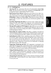
... Remote Ring On (requires modem): This allows a computer to be monitored for more than 4 seconds when the system is monitored by the ASUS ASIC through the CPU's internal thermal diode (on Pentium III, Pentium II (Deschutes), and PPGA370 Celeron in the mailbox. With this benefit ... and system damage. • Voltage Monitoring and Alert: System voltage levels are more memory and hard drive space to critical motherboard components. ASUS CUV4X User's Manual 11 The system resource monitor will warn the user before the system resources are set for its normal RPM range and alarm ...
... Remote Ring On (requires modem): This allows a computer to be monitored for more than 4 seconds when the system is monitored by the ASUS ASIC through the CPU's internal thermal diode (on Pentium III, Pentium II (Deschutes), and PPGA370 Celeron in the mailbox. With this benefit ... and system damage. • Voltage Monitoring and Alert: System voltage levels are more memory and hard drive space to critical motherboard components. ASUS CUV4X User's Manual 11 The system resource monitor will warn the user before the system resources are set for its normal RPM range and alarm ...
CUV4X User Manual
Page 12
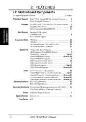
FEATURES 2.2 Motherboard Components See opposite page for Pentium III/Celeron/Joshua Processors 2 Feature Setting DIP Switches 6 Chipsets VIA VT82C694Z (VIA Apollo Pro133Z) system controller ..... 3 VIA...-On-LAN Connector 17 Wake-On-Ring Connector 13 Hardware Monitoring System Voltage Monitoring (integrated in ASUS ASIC) ....... 11 3 Fan Power and Speed Monitoring Connectors Power ATX Power Supply Connector 1 Special Feature Onboard LED 16 Form Factor ATX 12 ASUS CUV4X User's Manual Location Processor Support Socket 370 for locations. FEATURES Motherboard Parts 2. 2.
FEATURES 2.2 Motherboard Components See opposite page for Pentium III/Celeron/Joshua Processors 2 Feature Setting DIP Switches 6 Chipsets VIA VT82C694Z (VIA Apollo Pro133Z) system controller ..... 3 VIA...-On-LAN Connector 17 Wake-On-Ring Connector 13 Hardware Monitoring System Voltage Monitoring (integrated in ASUS ASIC) ....... 11 3 Fan Power and Speed Monitoring Connectors Power ATX Power Supply Connector 1 Special Feature Onboard LED 16 Form Factor ATX 12 ASUS CUV4X User's Manual Location Processor Support Socket 370 for locations. FEATURES Motherboard Parts 2. 2.

CUV4X User Manual
Page 14
HARDWARE SETUP 3.1 Motherboard Layout 20.9cm (8.22in) PS/2 VIO T: Mouse B: Keyboard USB1 USB2 COM1 cyrix 133 CPU_FAN Socket 370 ® DIMM Socket 1 (64/72-bit, 168-pin module) ... Modem Riser (AMR) WOR CUV4X ISA Slot VIA VT82C686A Chipset CR2032 3V Lithium Cell CMOS Power CLRTC JEN ASUS ASIC with Hardware Monitor JTPWR USBPORT SMB IDELED CHASSIS PANEL IR COM2 Flash EEPROM (Programable BIOS) Grayed components are optional at the time of purchase 30.5cm (12.0in) 14 ASUS CUV4X User's Manual 3. H/W SETUP Motherboard Layout 3.
HARDWARE SETUP 3.1 Motherboard Layout 20.9cm (8.22in) PS/2 VIO T: Mouse B: Keyboard USB1 USB2 COM1 cyrix 133 CPU_FAN Socket 370 ® DIMM Socket 1 (64/72-bit, 168-pin module) ... Modem Riser (AMR) WOR CUV4X ISA Slot VIA VT82C686A Chipset CR2032 3V Lithium Cell CMOS Power CLRTC JEN ASUS ASIC with Hardware Monitor JTPWR USBPORT SMB IDELED CHASSIS PANEL IR COM2 Flash EEPROM (Programable BIOS) Grayed components are optional at the time of purchase 30.5cm (12.0in) 14 ASUS CUV4X User's Manual 3. H/W SETUP Motherboard Layout 3.
CUV4X User Manual
Page 15
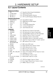
HARDWARE SETUP 3.2 Layout Contents Motherboard Settings 1) JEN p. 18 JumperFree Mode Setting (Disable/Enable) 2) AUDIOCODEC p. 19 Onboard Audio Setting 3) DIP_SW 5-8 p. 20 CPU External Frequency Selection 4) DIP_SW 1-4 p. 21 CPU Core:BUS Frequency ... p. 38 ATX Power Supply Connector (20 pins) 19) JTPWR p. 38 Power Supply Thermal Sensor Connector (2 pins) 20) SMB p. 39 SMBus Connector (5-1 pins) continued... 3. H/W SETUP LayoutContents 3. ASUS CUV4X User's Manual 15
HARDWARE SETUP 3.2 Layout Contents Motherboard Settings 1) JEN p. 18 JumperFree Mode Setting (Disable/Enable) 2) AUDIOCODEC p. 19 Onboard Audio Setting 3) DIP_SW 5-8 p. 20 CPU External Frequency Selection 4) DIP_SW 1-4 p. 21 CPU Core:BUS Frequency ... p. 38 ATX Power Supply Connector (20 pins) 19) JTPWR p. 38 Power Supply Thermal Sensor Connector (2 pins) 20) SMB p. 39 SMBus Connector (5-1 pins) continued... 3. H/W SETUP LayoutContents 3. ASUS CUV4X User's Manual 15
CUV4X User Manual
Page 17
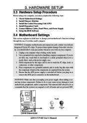
...from the system. 5. To protect them against damage from static electricity, you should follow some precautions whenever you work on the motherboard. Use a grounded wrist strap before you unplug your power supply when adding or removing system components. Connect Ribbon Cables, Panel Wires... chips, leads or connectors, or other components. 4. Install the Central Processing Unit (CPU) 4. WARNING! PLED CUV4X CUV4X Onboard LED ON Standby Power OFF Powered Off ASUS CUV4X User's Manual 17 Place components on a grounded antistatic pad or on the inside. 2. Check Motherboard Settings 2.
...from the system. 5. To protect them against damage from static electricity, you should follow some precautions whenever you work on the motherboard. Use a grounded wrist strap before you unplug your power supply when adding or removing system components. Connect Ribbon Cables, Panel Wires... chips, leads or connectors, or other components. 4. Install the Central Processing Unit (CPU) 4. WARNING! PLED CUV4X CUV4X Onboard LED ON Standby Power OFF Powered Off ASUS CUV4X User's Manual 17 Place components on a grounded antistatic pad or on the inside. 2. Check Motherboard Settings 2.

CUV4X User Manual
Page 18
... BIOS setup (see 4.4 Advanced Menu). H/W SETUP MotherboardSetings 3. The white block represents the switch's position. HARDWARE SETUP Motherboard Features Settings (DIP Switches - The example below shows all dip switches (DIP_SW) must be made through the DIP switches... Multiple < Frequency Multiple < Frequency Multiple < Frequency Multiple < Frequency Selection < Frequency Selection < Frequency Selection < Frequency Selection CUV4X CUV4X DIP Switches ON 12345678 ON OFF 1) JumperFree™ Mode (JEN) This jumper allows you to be set to OFF. 18 ASUS CUV4X User's Manual 3.
... BIOS setup (see 4.4 Advanced Menu). H/W SETUP MotherboardSetings 3. The white block represents the switch's position. HARDWARE SETUP Motherboard Features Settings (DIP Switches - The example below shows all dip switches (DIP_SW) must be made through the DIP switches... Multiple < Frequency Multiple < Frequency Multiple < Frequency Multiple < Frequency Selection < Frequency Selection < Frequency Selection < Frequency Selection CUV4X CUV4X DIP Switches ON 12345678 ON OFF 1) JumperFree™ Mode (JEN) This jumper allows you to be set to OFF. 18 ASUS CUV4X User's Manual 3.

CUV4X User Manual
Page 19
NOTE: This setting is available only on the AMR slot. H/W SETUP MotherboardSetings ASUS CUV4X User's Manual 19 3. If using an ISA or PCI audio expansion card, Onboard AC'97 Audio Controller in 4.4.2 I/O Device ...jumpers. HARDWARE SETUP 2) Onboard Audio Setting (AUDIOCODEC) The onboard audio CODEC may be disabled. Setting Enable Disable AUDIOCODEC [1-2] [1-2] [1-2] [1-2] (default) [2-3] [2-3] [2-3] [2-3] CUV4X CUV4X Audio Codec Setting 2 1 Enable (Default) 3 2 Disable SPK ADN# AUD_EN1 AUD_EN2 SPK ADN# AUD_EN1 AUD_EN2 3. Disable the onboard audio CODEC if you are using ...
NOTE: This setting is available only on the AMR slot. H/W SETUP MotherboardSetings ASUS CUV4X User's Manual 19 3. If using an ISA or PCI audio expansion card, Onboard AC'97 Audio Controller in 4.4.2 I/O Device ...jumpers. HARDWARE SETUP 2) Onboard Audio Setting (AUDIOCODEC) The onboard audio CODEC may be disabled. Setting Enable Disable AUDIOCODEC [1-2] [1-2] [1-2] [1-2] (default) [2-3] [2-3] [2-3] [2-3] CUV4X CUV4X Audio Codec Setting 2 1 Enable (Default) 3 2 Disable SPK ADN# AUD_EN1 AUD_EN2 SPK ADN# AUD_EN1 AUD_EN2 3. Disable the onboard audio CODEC if you are using ...

CUV4X User Manual
Page 22
...best performance vs. compliant DIMMs. • ASUS motherboards support SPD (Serial Presence Detect) DIMMs. This is recommended through SDRAM Configuration under "Chipset Features Setup". H/W SETUP SystemMemory 3. HARDWARE SETUP 3.5 System Memory (DIMM) This motherboard uses only Dual Inline Memory Modules (DIMMs... not supported on bootup screen. • Single-sided DIMMs come in 32, 64, 128, 256, 512MB. 22 ASUS CUV4X User's Manual 3. This motherboard also supports NEC's Virtual Channel (VC) SDRAMs and Enhanced Memory System's High-speed DRAMs (HSDRAMs). stability. •...
...best performance vs. compliant DIMMs. • ASUS motherboards support SPD (Serial Presence Detect) DIMMs. This is recommended through SDRAM Configuration under "Chipset Features Setup". H/W SETUP SystemMemory 3. HARDWARE SETUP 3.5 System Memory (DIMM) This motherboard uses only Dual Inline Memory Modules (DIMMs... not supported on bootup screen. • Single-sided DIMMs come in 32, 64, 128, 256, 512MB. 22 ASUS CUV4X User's Manual 3. This motherboard also supports NEC's Virtual Channel (VC) SDRAMs and Enhanced Memory System's High-speed DRAMs (HSDRAMs). stability. •...
CUV4X User Manual
Page 23
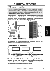
... module will shift between left, center, or right to identify the type and also to both sides. Insert the module(s) as shown. This motherboard supports four clock signals per DIMM. Because the number of pins are different on the DIMMs (see 3.3 Hardware Setup Procedure for more information). DRAM... pin contacts on each side and therefore have the same pin contacts on the DIMM will only fit in the orientation shown. ASUS CUV4X User's Manual 23 Make sure that you unplug your motherboard and expansion cards (see figure below). 168-Pin DIMM Notch Key Definitions (3.3V) 3. 3.
... module will shift between left, center, or right to identify the type and also to both sides. Insert the module(s) as shown. This motherboard supports four clock signals per DIMM. Because the number of pins are different on the DIMMs (see 3.3 Hardware Setup Procedure for more information). DRAM... pin contacts on each side and therefore have the same pin contacts on the DIMM will only fit in the orientation shown. ASUS CUV4X User's Manual 23 Make sure that you unplug your motherboard and expansion cards (see figure below). 168-Pin DIMM Notch Key Definitions (3.3V) 3. 3.

CUV4X User Manual
Page 25
... on unlocked processors) for reference only; Without sufficient circulation, the processor could overheat and damage both the processor and the motherboard. Locate the ZIF socket and open it to scrape the motherboard when mounting a clampstyle processor fan or else damage may install an auxiliary fan, if necessary. HARDWARE SETUP 3.6 Central Processing Unit... weight of the four corners, the CPU will only fit in the orientation as shown. Socket 370 CPU (Top) Socket 370 CPU (Bottom) Celeron Notch CUV4X CUV4X Socket 370 Pentium III Gold Arrow ASUS CUV4X User's Manual 25
... on unlocked processors) for reference only; Without sufficient circulation, the processor could overheat and damage both the processor and the motherboard. Locate the ZIF socket and open it to scrape the motherboard when mounting a clampstyle processor fan or else damage may install an auxiliary fan, if necessary. HARDWARE SETUP 3.6 Central Processing Unit... weight of the four corners, the CPU will only fit in the orientation as shown. Socket 370 CPU (Top) Socket 370 CPU (Bottom) Celeron Notch CUV4X CUV4X Socket 370 Pentium III Gold Arrow ASUS CUV4X User's Manual 25

CUV4X User Manual
Page 26
Unplug your motherboard and expansion cards. 3.7.1 Expansion Card Installation Procedure 1. Failure to do so may cause severe damage to use . 3. Remove your computer system's cover and the bracket ... the bracket for possible future use . Replace the computer system's cover. 6. Install the necessary software drivers for your expansion card. 3. H/W SETUP Expansion Cards 26 ASUS CUV4X User's Manual 3. Set up the BIOS if necessary (such as jumpers. 2. HARDWARE SETUP 3.7 Expansion Cards WARNING! Read the documentation for your expansion card and make any necessary...
Unplug your motherboard and expansion cards. 3.7.1 Expansion Card Installation Procedure 1. Failure to do so may cause severe damage to use . 3. Remove your computer system's cover and the bracket ... the bracket for possible future use . Replace the computer system's cover. 6. Install the necessary software drivers for your expansion card. 3. H/W SETUP Expansion Cards 26 ASUS CUV4X User's Manual 3. Set up the BIOS if necessary (such as jumpers. 2. HARDWARE SETUP 3.7 Expansion Cards WARNING! Read the documentation for your expansion card and make any necessary...

CUV4X User Manual
Page 27
IMPORTANT: If using PCI cards on shared slots, make the system unstable or cards inoperable. Use this Motherboard PCI slot 1 PCI slot 2 PCI slot 3 PCI slot 4 PCI slot 5 AGP Pro slot Onboard USB controller Onboard audio/AMR INT-A shared - - - shared shared -...cards. ASUS CUV4X User's Manual 27 H/W SETUP Expansion Cards 3. HARDWARE SETUP 3.7.2 Assigning IRQs for PCI Steering PS/2 Compatible Mouse Port Numeric Data Processor Primary IDE Channel Secondary IDE Channel *These IRQs are already in use . Generally, an IRQ must be exclusively assigned to operate. If your motherboard has ...
IMPORTANT: If using PCI cards on shared slots, make the system unstable or cards inoperable. Use this Motherboard PCI slot 1 PCI slot 2 PCI slot 3 PCI slot 4 PCI slot 5 AGP Pro slot Onboard USB controller Onboard audio/AMR INT-A shared - - - shared shared -...cards. ASUS CUV4X User's Manual 27 H/W SETUP Expansion Cards 3. HARDWARE SETUP 3.7.2 Assigning IRQs for PCI Steering PS/2 Compatible Mouse Port Numeric Data Processor Primary IDE Channel Secondary IDE Channel *These IRQs are already in use . Generally, an IRQ must be exclusively assigned to operate. If your motherboard has ...
CUV4X User Manual
Page 28
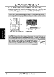
...and remove the tab from the bay. H/W SETUP Expansion Cards 28 ASUS CUV4X User's Manual 3. DO NOT remove this tab if you will be using an AGP Pro card. Remove ONLY when you will be unplugged before inserting your card, slot, and motherboard. The AGP Pro slot is shipped with a safety tab on ...the 20-pin bay for use with AGP cards without Retention Notch 20-pin bay Rib (inside slot) CUV4X CUV4X Accelerated Graphics Port (AGP PRO) TOP VIEW 28-pin bay ...
...and remove the tab from the bay. H/W SETUP Expansion Cards 28 ASUS CUV4X User's Manual 3. DO NOT remove this tab if you will be using an AGP Pro card. Remove ONLY when you will be unplugged before inserting your card, slot, and motherboard. The AGP Pro slot is shipped with a safety tab on ...the 20-pin bay for use with AGP cards without Retention Notch 20-pin bay Rib (inside slot) CUV4X CUV4X Accelerated Graphics Port (AGP PRO) TOP VIEW 28-pin bay ...

CUV4X User Manual
Page 29
... CODEC (optional) must be disabled when using a primary AMR. NOTE: An AMR is done through software and controlled by the motherboard's system chipset. H/W SETUP Expansion Cards ASUS CUV4X User's Manual 29 CUV4X CUV4X Audio Modem Riser (AMR) Connector 3. There are two types of AMR, one defined as primary and another defined as secondary. This provides an...
... CODEC (optional) must be disabled when using a primary AMR. NOTE: An AMR is done through software and controlled by the motherboard's system chipset. H/W SETUP Expansion Cards ASUS CUV4X User's Manual 29 CUV4X CUV4X Audio Modem Riser (AMR) Connector 3. There are two types of AMR, one defined as primary and another defined as secondary. This provides an...


