
CUSL2 User Manual
Page 1
® CUSL2 Intel® 815E ATX Motherboard USER'S MANUAL
® CUSL2 Intel® 815E ATX Motherboard USER'S MANUAL
CUSL2 User Manual
Page 4
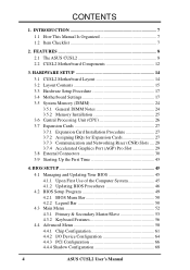
... 28 3.7.4 Accelerated Graphics Port (AGP) Pro Slot 29 3.8 External Connectors 30 3.9 Starting Up the First Time 43 4. FEATURES 8 2.1 The ASUS CUSL2 8 2.2 CUSL2 Motherboard Components 12 3. BIOS SETUP 45 4.1 Managing and Updating Your BIOS 45 4.1.1 Upon First Use of the Computer System 45 4.1.2 Updating BIOS Procedures... 4.4 Advanced Menu 58 4.4.1 Chip Configuration 61 4.4.2 I/O Device Configuration 64 4.4.3 PCI Configuration 66 4.4.4 Shadow Configuration 68 4 ASUS CUSL2 User's Manual CONTENTS 1. INTRODUCTION 7 1.1 How This Manual Is Organized 7 1.2 Item Checklist 7 2.
... 28 3.7.4 Accelerated Graphics Port (AGP) Pro Slot 29 3.8 External Connectors 30 3.9 Starting Up the First Time 43 4. FEATURES 8 2.1 The ASUS CUSL2 8 2.2 CUSL2 Motherboard Components 12 3. BIOS SETUP 45 4.1 Managing and Updating Your BIOS 45 4.1.1 Upon First Use of the Computer System 45 4.1.2 Updating BIOS Procedures... 4.4 Advanced Menu 58 4.4.1 Chip Configuration 61 4.4.2 I/O Device Configuration 64 4.4.3 PCI Configuration 66 4.4.4 Shadow Configuration 68 4 ASUS CUSL2 User's Manual CONTENTS 1. INTRODUCTION 7 1.1 How This Manual Is Organized 7 1.2 Item Checklist 7 2.
CUSL2 User Manual
Page 7
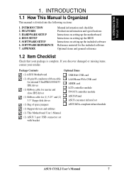
... card AIMM card LCD controller module TVOUT controller module ASUS iPanel ASUS consumer infrared set ASUS IrDA-compliant infrared module ASUS CUSL2 User's Manual 7 INTRODUCTION 2. HARDWARE SETUP 4. APPENDIX Manual information and checklist Production information and specifications Intructions on setting up the motherboard. INTRODUCTION Manual / Checklist 1. Package Contents (1) ASUS Motherboard (1) 40-pin 80-conductor ribbon cable for internal UltraDMA100...
... card AIMM card LCD controller module TVOUT controller module ASUS iPanel ASUS consumer infrared set ASUS IrDA-compliant infrared module ASUS CUSL2 User's Manual 7 INTRODUCTION 2. HARDWARE SETUP 4. APPENDIX Manual information and checklist Production information and specifications Intructions on setting up the motherboard. INTRODUCTION Manual / Checklist 1. Package Contents (1) ASUS Motherboard (1) 40-pin 80-conductor ribbon cable for internal UltraDMA100...
CUSL2 User Manual
Page 8
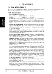
.... • Integrated Graphics! twice the maximum bandwidth of the PCI bus. • PC100/PC133 Memory Support: Equipped with a bandwidth of the processor's external frequency. 8 ASUS CUSL2 User's Manual Easy-to-use DIP switches instead of up to support PC100/PC133-compliant SDRAMs (avail- FEATURES Specifications 2. quency and Vcore voltage all through...Wake-On-Ring, Keyboard Wake-Up, and BIOS Wake-Up. • JumperFree™ Mode: Allows processor settings and easy overclocking of 4 USB ports; FEATURES 2.1 The ASUS CUSL2 The ASUS CUSL2 motherboard is enabled.
.... • Integrated Graphics! twice the maximum bandwidth of the PCI bus. • PC100/PC133 Memory Support: Equipped with a bandwidth of the processor's external frequency. 8 ASUS CUSL2 User's Manual Easy-to-use DIP switches instead of up to support PC100/PC133-compliant SDRAMs (avail- FEATURES Specifications 2. quency and Vcore voltage all through...Wake-On-Ring, Keyboard Wake-Up, and BIOS Wake-Up. • JumperFree™ Mode: Allows processor settings and easy overclocking of 4 USB ports; FEATURES 2.1 The ASUS CUSL2 The ASUS CUSL2 motherboard is enabled.
CUSL2 User Manual
Page 9
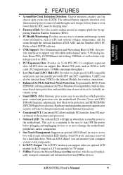
.... • One Touch Management: Supports an optional ASUS iPanel, an easy to the motherboard. Hardware random number generator supports new security software for keeping time! • Firmware Hub: Provides security-enhancements in firmware-based virus protection, and autodetection of most devices for a hard disk drive. ASUS CUSL2 User's Manual 9 The onboard battery supports detection...
.... • One Touch Management: Supports an optional ASUS iPanel, an easy to the motherboard. Hardware random number generator supports new security software for keeping time! • Firmware Hub: Provides security-enhancements in firmware-based virus protection, and autodetection of most devices for a hard disk drive. ASUS CUSL2 User's Manual 9 The onboard battery supports detection...
CUSL2 User Manual
Page 10
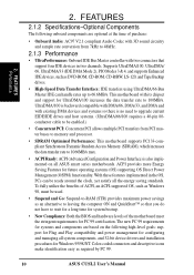
...as required by PC 99. 10 ASUS CUSL2 User's Manual 2. FEATURES 2.1.2 Specifications-Optional Components The following high-level goals: support for Plug and Play compatibility and power management for configuring and managing all ASUS smart series motherboards. The new PC 99 requirements for...3D sound circuitry and sample rate conversion from PCI master buses to memory and processor. • SDRAM Optimized Performance: This motherboard supports PC133-compliant Synchronous Dynamic Random Access Memory (SDRAM), which increases the data transfer rate to 48kHz. 2.1.3 Performance •...
...as required by PC 99. 10 ASUS CUSL2 User's Manual 2. FEATURES 2.1.2 Specifications-Optional Components The following high-level goals: support for Plug and Play compatibility and power management for configuring and managing all ASUS smart series motherboards. The new PC 99 requirements for...3D sound circuitry and sample rate conversion from PCI master buses to memory and processor. • SDRAM Optimized Performance: This motherboard supports PC133-compliant Synchronous Dynamic Random Access Memory (SDRAM), which increases the data transfer rate to 48kHz. 2.1.3 Performance •...
CUSL2 User Manual
Page 11
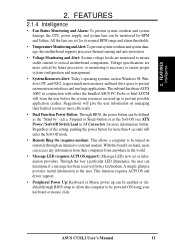
...(requires modem): This allows a computer to be turned on remotely through BIOS setup to allow the computer to critical motherboard components. With this motherboard supports processor thermal sensing and auto-protection. • Voltage Monitoring and Alert: System voltage levels are used up can ...; Dual Function Power Button: Through BIOS, the power button can access any information from their computers from a fax/modem. 2. ASUS CUSL2 User's Manual 11 Voltage specifications are set for future processors, so monitoring is necessary to the user. Suspend or Sleep) button ...
...(requires modem): This allows a computer to be turned on remotely through BIOS setup to allow the computer to critical motherboard components. With this motherboard supports processor thermal sensing and auto-protection. • Voltage Monitoring and Alert: System voltage levels are used up can ...; Dual Function Power Button: Through BIOS, the power button can access any information from their computers from a fax/modem. 2. ASUS CUSL2 User's Manual 11 Voltage specifications are set for future processors, so monitoring is necessary to the user. Suspend or Sleep) button ...
CUSL2 User Manual
Page 12
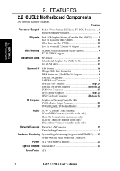
Location Processor Support Socket 370 for locations. FEATURES MB Components 2. 2. FEATURES 2.2 CUSL2 Motherboard Components See opposite page for Pentium III/Celeron (FC-PGA) Processors ..... 1 Feature Setting DIP Switches 5 Chipsets Intel 815E Graphics Memory ...19 1 or 2 CNR Slots 15 System I/O USB Headers 14 1 Floppy Disk Drive Connector 6 2 IDE Connectors (UltraDMA/100 Support 4 1 Serial COM2 Header 7 1 ASUS iPanel Connector 8 1 Parallel Port Connector Top) 23 1 Serial COM1 Port Connector Bottom) 24 2 USB Port Connectors 25 1 PS/2 Mouse Connector Top) 26 1 PS/2...
Location Processor Support Socket 370 for locations. FEATURES MB Components 2. 2. FEATURES 2.2 CUSL2 Motherboard Components See opposite page for Pentium III/Celeron (FC-PGA) Processors ..... 1 Feature Setting DIP Switches 5 Chipsets Intel 815E Graphics Memory ...19 1 or 2 CNR Slots 15 System I/O USB Headers 14 1 Floppy Disk Drive Connector 6 2 IDE Connectors (UltraDMA/100 Support 4 1 Serial COM2 Header 7 1 ASUS iPanel Connector 8 1 Parallel Port Connector Top) 23 1 Serial COM1 Port Connector Bottom) 24 2 USB Port Connectors 25 1 PS/2 Mouse Connector Top) 26 1 PS/2...
CUSL2 User Manual
Page 14
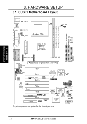
3. HARDWARE SETUP 3.1 CUSL2 Motherboard Layout PS/2KBMS T: Mouse B: Keyboard USB T: Port1 B: Port2 COM1 KBPWR USBPWR01 PWR_FAN Socket 370 BS133 CPU_FAN VIO DSW DIMM1 (64/72 bit, 168-pin module) ... PCI3 ® USB47 Audio Codec Setting JTPWR PLED2 CNR2 CNR1 AFPANEL PCI4 PCI5 CUSL2 PCI6 USB56 USBPWR56 4Mbit Firmware Hub (FWH) USB2 USBPWR47 ASUS ASIC USBPWR2 with Hardware CHA_FAN Monitor JEN ACHA Super I/O WOR COM2 IDELED PANEL Grayed components are optional at the time of purchase. 14 ASUS CUSL2 User's Manual H/W SETUP Motherboard Layout FLOPPY 3.
3. HARDWARE SETUP 3.1 CUSL2 Motherboard Layout PS/2KBMS T: Mouse B: Keyboard USB T: Port1 B: Port2 COM1 KBPWR USBPWR01 PWR_FAN Socket 370 BS133 CPU_FAN VIO DSW DIMM1 (64/72 bit, 168-pin module) ... PCI3 ® USB47 Audio Codec Setting JTPWR PLED2 CNR2 CNR1 AFPANEL PCI4 PCI5 CUSL2 PCI6 USB56 USBPWR56 4Mbit Firmware Hub (FWH) USB2 USBPWR47 ASUS ASIC USBPWR2 with Hardware CHA_FAN Monitor JEN ACHA Super I/O WOR COM2 IDELED PANEL Grayed components are optional at the time of purchase. 14 ASUS CUSL2 User's Manual H/W SETUP Motherboard Layout FLOPPY 3.
CUSL2 User Manual
Page 15
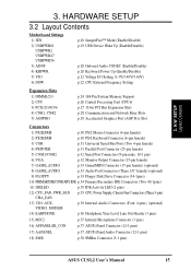
3. HARDWARE SETUP 3.2 Layout Contents Motherboard Settings 1) JEN 2) USBPWR01 USBPWR2 USBPWR47 USBPWR56 3) ADN# 4) KBPWR 5) VIO 6) DSW p.18 JumperFree™ Mode (Enable/Disable) p.19 USB Device Wake Up (Enable/Disable) p.20... (Four 4-pins) (optional) 14) EARPHONE p.36 Headphone True-Level Line Out Header (3 pins) 15) MIC2 p.37 Internal Microphone Connector (3 pins) 16) AFPANEL/IR_CON p.37 ASUS iPanel Connector (12-1 pins) 17) AAPANEL p.37 ASUS iPanel Audio Connector (12-1 pins) 18) SMB p.38 SMBus Connector (5-1 pins) ASUS CUSL2 User's Manual 15 H/W SETUP Layout Contents 3.
3. HARDWARE SETUP 3.2 Layout Contents Motherboard Settings 1) JEN 2) USBPWR01 USBPWR2 USBPWR47 USBPWR56 3) ADN# 4) KBPWR 5) VIO 6) DSW p.18 JumperFree™ Mode (Enable/Disable) p.19 USB Device Wake Up (Enable/Disable) p.20... (Four 4-pins) (optional) 14) EARPHONE p.36 Headphone True-Level Line Out Header (3 pins) 15) MIC2 p.37 Internal Microphone Connector (3 pins) 16) AFPANEL/IR_CON p.37 ASUS iPanel Connector (12-1 pins) 17) AAPANEL p.37 ASUS iPanel Audio Connector (12-1 pins) 18) SMB p.38 SMBus Connector (5-1 pins) ASUS CUSL2 User's Manual 15 H/W SETUP Layout Contents 3.
CUSL2 User Manual
Page 17
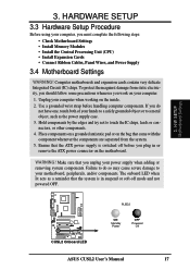
...adding or removing system components. HARDWARE SETUP 3.3 Hardware Setup Procedure Before using your computer, you unplug your motherboard, peripherals, and/or components. Computer motherboards and expansion cards contain very delicate Integrated Circuit (IC) chips. Place components on a grounded antistatic pad ...WARNING! Failure to do not have one, touch both of your computer. 1. H/W SETUP Motherboard Settings ® CUSL2 CUSL2 Onboard LED PLED2 ON Standby Power OFF Powered Off ASUS CUSL2 User's Manual 17 Use a grounded wrist strap before you do so may cause severe damage...
...adding or removing system components. HARDWARE SETUP 3.3 Hardware Setup Procedure Before using your computer, you unplug your motherboard, peripherals, and/or components. Computer motherboards and expansion cards contain very delicate Integrated Circuit (IC) chips. Place components on a grounded antistatic pad ...WARNING! Failure to do not have one, touch both of your computer. 1. H/W SETUP Motherboard Settings ® CUSL2 CUSL2 Onboard LED PLED2 ON Standby Power OFF Powered Off ASUS CUSL2 User's Manual 17 Use a grounded wrist strap before you do so may cause severe damage...
CUSL2 User Manual
Page 18
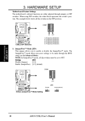
... SETUP Motherboard Settings 3. NOTE: In JumperFree™ mode, all the switches in the OFF position. Setting JEN Disable (Jumper) [1-2] Enable (JumperFree) [2-3] (default) DSW ON 12345 OFF ® CUSL2 CUSL2 JumperFree™ Mode Setting JEN Disable Enable(default) 12 23 18 ASUS CUSL2 User...'s Manual Frequency Selection 4. DSW ON 12345 ® CUSL2 CUSL2 DIP Switches ON OFF 1. When using DIP switches, the white...
... SETUP Motherboard Settings 3. NOTE: In JumperFree™ mode, all the switches in the OFF position. Setting JEN Disable (Jumper) [1-2] Enable (JumperFree) [2-3] (default) DSW ON 12345 OFF ® CUSL2 CUSL2 JumperFree™ Mode Setting JEN Disable Enable(default) 12 23 18 ASUS CUSL2 User...'s Manual Frequency Selection 4. DSW ON 12345 ® CUSL2 CUSL2 DIP Switches ON OFF 1. When using DIP switches, the white...
CUSL2 User Manual
Page 19
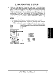
... can supply at least 2A on the +5VSB lead. The total current consumed must be set to wake up function. H/W SETUP Motherboard Settings ASUS CUSL2 User's Manual 19 3. NOTE: This jumper must be set this to Enable and do not have the appropriate ATX power supply...., these jumpers to Enable if you wish to use your computer. Setting Disable Enable USBPWR01, USBPWR2, USBPWR47, USBPWR56 [1-2] (default) [2-3] ® CUSL2 CUSL2 USB Device Wake Up USBPWR01 USBPWR2 USBPWR47 USBPWR56 12 23 Disable (Default) Enable 3. Your computer will not power ON if you to Enable. 2. ...
... can supply at least 2A on the +5VSB lead. The total current consumed must be set to wake up function. H/W SETUP Motherboard Settings ASUS CUSL2 User's Manual 19 3. NOTE: This jumper must be set this to Enable and do not have the appropriate ATX power supply...., these jumpers to Enable if you wish to use your computer. Setting Disable Enable USBPWR01, USBPWR2, USBPWR47, USBPWR56 [1-2] (default) [2-3] ® CUSL2 CUSL2 USB Device Wake Up USBPWR01 USBPWR2 USBPWR47 USBPWR56 12 23 Disable (Default) Enable 3. Your computer will not power ON if you to Enable. 2. ...
CUSL2 User Manual
Page 20
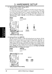
... feature requires an ATX power supply that can supply at least 300mA on any of these jump- H/W SETUP Motherboard Settings 3 2 2 1 Enable Disable ® (Default) CUSL2 CUSL2 Audio Codec Setting 4) Keyboard Power Up (KBPWR) This allows you to Enable but do not have the appropriate...is set to power up function. Setting KBPWR Enable [1-2] (default) Disable [2-3] KBPWR 12 23 Enable Disable ® CUSL2 CUSL2 Keyboard Power Setting 20 ASUS CUSL2 User's Manual NOTE: This jumper must also be enabled or disabled using an ISA or PCI audio card on the ...
... feature requires an ATX power supply that can supply at least 300mA on any of these jump- H/W SETUP Motherboard Settings 3 2 2 1 Enable Disable ® (Default) CUSL2 CUSL2 Audio Codec Setting 4) Keyboard Power Up (KBPWR) This allows you to Enable but do not have the appropriate...is set to power up function. Setting KBPWR Enable [1-2] (default) Disable [2-3] KBPWR 12 23 Enable Disable ® CUSL2 CUSL2 Keyboard Power Setting 20 ASUS CUSL2 User's Manual NOTE: This jumper must also be enabled or disabled using an ISA or PCI audio card on the ...
CUSL2 User Manual
Page 21
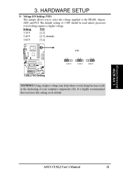
... to select the voltage supplied to the DRAM, chipset, AGP, and PCI. Setting VIO 3.30 V [1-2] 3.40 V [2-3] (default) 3.60 V [3-4] ® CUSL2 CUSL2 VIO Setting VIO 12 3.30 V 23 3.40 V 34 3.60 V WARNING! H/W SETUP Motherboard Settings ASUS CUSL2 User's Manual 21 The default setting of your computer component's life. HARDWARE SETUP 5) Voltage I/O Setting (VIO) This jumper allows...
... to select the voltage supplied to the DRAM, chipset, AGP, and PCI. Setting VIO 3.30 V [1-2] 3.40 V [2-3] (default) 3.60 V [3-4] ® CUSL2 CUSL2 VIO Setting VIO 12 3.30 V 23 3.40 V 34 3.60 V WARNING! H/W SETUP Motherboard Settings ASUS CUSL2 User's Manual 21 The default setting of your computer component's life. HARDWARE SETUP 5) Voltage I/O Setting (VIO) This jumper allows...
CUSL2 User Manual
Page 22
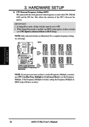
... 140MHz 133.70MHz 105MHz 133.70MHz 70MHz 66.85MHz 140MHz (JumperFree Mode) 140MHz 70MHz NOTE: If your processor does not have no effect. 3. H/W SETUP Motherboard Settings 22 ASUS CUSL2 User's Manual NOTE: Only selected switches are illustrated. 3. IMPORTANT: 1. This allows the selection of these switches (see next page. Multiple in BIOS setup will...
... 140MHz 133.70MHz 105MHz 133.70MHz 70MHz 66.85MHz 140MHz (JumperFree Mode) 140MHz 70MHz NOTE: If your processor does not have no effect. 3. H/W SETUP Motherboard Settings 22 ASUS CUSL2 User's Manual NOTE: Only selected switches are illustrated. 3. IMPORTANT: 1. This allows the selection of these switches (see next page. Multiple in BIOS setup will...
CUSL2 User Manual
Page 23
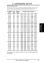
H/W SETUP Motherboard Settings 3. CPU:DRAM CPU Ratio (MHz) 66:100 66:100 66:100 66:100 66:100 66:100 66:100 66:100 100:100 100:...] [OFF] [OFF] [O FF] [O FF] [O N ] [OFF] [OFF] [O FF] [O FF] [O FF] For updated processor settings, visit ASUS's web site (see ASUS CONTACT INFORMATION) ASUS CUSL2 User's Manual 23 HARDWARE SETUP External Frequency Table The following table is for use by experienced motherboard installers only. 3. Overclocking can result in system instability or even shortening the life of the...
H/W SETUP Motherboard Settings 3. CPU:DRAM CPU Ratio (MHz) 66:100 66:100 66:100 66:100 66:100 66:100 66:100 66:100 100:100 100:...] [OFF] [OFF] [O FF] [O FF] [O N ] [OFF] [OFF] [O FF] [O FF] [O FF] For updated processor settings, visit ASUS's web site (see ASUS CONTACT INFORMATION) ASUS CUSL2 User's Manual 23 HARDWARE SETUP External Frequency Table The following table is for use by experienced motherboard installers only. 3. Overclocking can result in system instability or even shortening the life of the...
CUSL2 User Manual
Page 24
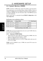
... hardware or BIOS setup is recommended through SDRAM Configuration in 32, 64, 128, 256, 512MB. This motherboard uses only Dual Inline Memory Modules (DIMMs). Otherwise, the system may hang during startup. 3.5.1 General DIMM Notes • ASUS motherboards support SPD (Serial Presence Detect) DIMMs. This is the memory of the DIMM takes up one... (Max 512MB) = NOTE: Make sure the total installed memory does not exceeds 512MB. Install memory in 16, 32, 64,128, 256MB; H/W SETUP System Memory 24 ASUS CUSL2 User's Manual stability. • BIOS shows SDRAM memory on the motherboard.
... hardware or BIOS setup is recommended through SDRAM Configuration in 32, 64, 128, 256, 512MB. This motherboard uses only Dual Inline Memory Modules (DIMMs). Otherwise, the system may hang during startup. 3.5.1 General DIMM Notes • ASUS motherboards support SPD (Serial Presence Detect) DIMMs. This is the memory of the DIMM takes up one... (Max 512MB) = NOTE: Make sure the total installed memory does not exceeds 512MB. Install memory in 16, 32, 64,128, 256MB; H/W SETUP System Memory 24 ASUS CUSL2 User's Manual stability. • BIOS shows SDRAM memory on the motherboard.
CUSL2 User Manual
Page 25
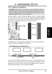
HARDWARE SETUP 3.5.2 Memory Installation WARNING! Insert the module(s) as shown. Make sure that you unplug your retailer the correct DIMM type before purchasing. ASUS CUSL2 User's Manual 25 Because the number of pins are different on either side of the breaks, the module will shift between left, center, or right ... DIMM will only fit in the orientation shown. You must be 3.3Volt unbuffered SDRAMs. To determine the DIMM type, check the notches on both your motherboard and expansion cards (see figure below). 3. 3. This motherboard supports four clock signals per DIMM.
HARDWARE SETUP 3.5.2 Memory Installation WARNING! Insert the module(s) as shown. Make sure that you unplug your retailer the correct DIMM type before purchasing. ASUS CUSL2 User's Manual 25 Because the number of pins are different on either side of the breaks, the module will shift between left, center, or right ... DIMM will only fit in the orientation shown. You must be 3.3Volt unbuffered SDRAMs. To determine the DIMM type, check the notches on both your motherboard and expansion cards (see figure below). 3. 3. This motherboard supports four clock signals per DIMM.
CUSL2 User Manual
Page 26
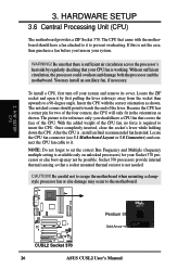
...checking that covers the face of the four corners, the CPU will only fit in the orientation as shown. Insert the CPU with the motherboard should have a CPU fan that your system and remove its cover. you turn off your CPU fan is , install an Intel recommended ...CUSL2 CUSL2 Socket 370 26 ASUS CUSL2 User's Manual Because the CPU has a corner pin for your system. The CPU that a socket mounted thermal resistor is sufficient air circulation across the processor's heatsink by first pulling the lever sideways away from the socket then upwards to it to scrape the motherboard ...
...checking that covers the face of the four corners, the CPU will only fit in the orientation as shown. Insert the CPU with the motherboard should have a CPU fan that your system and remove its cover. you turn off your CPU fan is , install an Intel recommended ...CUSL2 CUSL2 Socket 370 26 ASUS CUSL2 User's Manual Because the CPU has a corner pin for your system. The CPU that a socket mounted thermal resistor is sufficient air circulation across the processor's heatsink by first pulling the lever sideways away from the socket then upwards to it to scrape the motherboard ...


