
CUSL2-C BP User Manual
Page 16
3. H/W SETUP Motherboard Layout 3. HARDWARE SETUP 3.1 CUSL2-C Black Pearl Layout PS/2KBMS T: Mouse B: Keyboard USB T: Port1 B: Port2 COM1 KBPWR USBPWR01 PWR_FAN Socket 370 CPU_FAN VIO DSW DIMM1 (64/72 bit, 168-pin ...) PCI1 PCI2 WOL_CON SMB PCI3 JTPWR CR2032 3V Lithium Cell CMOS Power Intel I/O Controller Hub (ICH2) CLRTC ® AFPANEL PCI4 USB2 PLED2 PCI5 CUSL2-C BP Firmware Hub (FWH) ASUS ASIC with Hardware Monitor JEN ACHA WOR USBPWR2 CHA_FAN PCI6 CNR_SLOT USBPWR56 USB56 Super I/O SMARTCON IDELED PANEL Grayed components are optional at the time...
3. H/W SETUP Motherboard Layout 3. HARDWARE SETUP 3.1 CUSL2-C Black Pearl Layout PS/2KBMS T: Mouse B: Keyboard USB T: Port1 B: Port2 COM1 KBPWR USBPWR01 PWR_FAN Socket 370 CPU_FAN VIO DSW DIMM1 (64/72 bit, 168-pin ...) PCI1 PCI2 WOL_CON SMB PCI3 JTPWR CR2032 3V Lithium Cell CMOS Power Intel I/O Controller Hub (ICH2) CLRTC ® AFPANEL PCI4 USB2 PLED2 PCI5 CUSL2-C BP Firmware Hub (FWH) ASUS ASIC with Hardware Monitor JEN ACHA WOR USBPWR2 CHA_FAN PCI6 CNR_SLOT USBPWR56 USB56 Super I/O SMARTCON IDELED PANEL Grayed components are optional at the time...

CUSL2-C BP User Manual
Page 19
... Settings WARNING! 3. If you do so may cause severe damage to touch the IC chips, leads or connectors, or other components. 4. H/W SETUP Motherboard Settings ® CUSL2-C BP CUSL2-C BP Onboard LED PLED2 ON Standby Power OFF Powered Off ASUS CUSL2-C Black PearlUser's Manual 19
... Settings WARNING! 3. If you do so may cause severe damage to touch the IC chips, leads or connectors, or other components. 4. H/W SETUP Motherboard Settings ® CUSL2-C BP CUSL2-C BP Onboard LED PLED2 ON Standby Power OFF Powered Off ASUS CUSL2-C Black PearlUser's Manual 19

CUSL2-C BP User Manual
Page 20
...switches. Frequency Selection 2. Setting JEN Disable (Jumper) [1-2] Enable (JumperFree) [2-3] (default) DSW ON 12345 ® CUSL2-C BP CUSL2-C BP JumperFree™ Mode Setting OFF JEN Disable Enable(default) 12 23 20 ASUS CUSL2-C Black PearlUser's Manual Frequency Selection. 1) JumperFree™ Mode (JEN) This jumper allows you to be set to...8482; mode. When using DIP switches, the white block represents the switch's position. 3. DSW ON 12345 ® CUSL2-C BP CUSL2-C BP DIP Switches ON OFF 1. Frequency Selection 3. Frequency Selection 4. Frequency Selection 5.
...switches. Frequency Selection 2. Setting JEN Disable (Jumper) [1-2] Enable (JumperFree) [2-3] (default) DSW ON 12345 ® CUSL2-C BP CUSL2-C BP JumperFree™ Mode Setting OFF JEN Disable Enable(default) 12 23 20 ASUS CUSL2-C Black PearlUser's Manual Frequency Selection. 1) JumperFree™ Mode (JEN) This jumper allows you to be set to...8482; mode. When using DIP switches, the white block represents the switch's position. 3. DSW ON 12345 ® CUSL2-C BP CUSL2-C BP DIP Switches ON OFF 1. Frequency Selection 3. Frequency Selection 4. Frequency Selection 5.

CUSL2-C BP User Manual
Page 21
...power supply. The default is set to Enable. 2. NOTES 1. Setting Disable Enable USBPWR01, USBPWR2, USBPWR56 [1-2] (default) [2-3] ® CUSL2-C BP CUSL2-C BP USB Device Wake Up USBPWR01 USBPWR2 USBPWR56 12 Disable (Default) 23 Enable 3. For suspend to RAM function, these jumpers to Enable if...exceed the power supply capability (+5VSB) whether under normal working conditions or in 4.5.1 Power Up Control. H/W SETUP Motherboard Settings ASUS CUSL2-C Black PearlUser's Manual 21 The total current consumed must be set to Enable and do not have the appropriate ATX power...
...power supply. The default is set to Enable. 2. NOTES 1. Setting Disable Enable USBPWR01, USBPWR2, USBPWR56 [1-2] (default) [2-3] ® CUSL2-C BP CUSL2-C BP USB Device Wake Up USBPWR01 USBPWR2 USBPWR56 12 Disable (Default) 23 Enable 3. For suspend to RAM function, these jumpers to Enable if...exceed the power supply capability (+5VSB) whether under normal working conditions or in 4.5.1 Power Up Control. H/W SETUP Motherboard Settings ASUS CUSL2-C Black PearlUser's Manual 21 The total current consumed must be set to Enable and do not have the appropriate ATX power...

CUSL2-C BP User Manual
Page 22
...PS2 KB/ PS2 Mouse/CIR in 4.5.1 Power Up Control. Setting KBPWR Enable [1-2] (default) Disable [2-3] KBPWR 12 23 Enable Disable ® CUSL2-C BP CUSL2-C BP Keyboard Power Setting 3. HARDWARE SETUP 3) Keyboard Power Up (KBPWR) This allows you wish to use your keyboard (by pressing ) to disable ...3. NOTE: This jumper must be set this jumper to Enable if you to power up function. H/W SETUP Motherboard Settings 22 ASUS CUSL2-C Black PearlUser's Manual Set this to Disable because not all computers have the appropriate ATX power supply. This feature requires an ...
...PS2 KB/ PS2 Mouse/CIR in 4.5.1 Power Up Control. Setting KBPWR Enable [1-2] (default) Disable [2-3] KBPWR 12 23 Enable Disable ® CUSL2-C BP CUSL2-C BP Keyboard Power Setting 3. HARDWARE SETUP 3) Keyboard Power Up (KBPWR) This allows you wish to use your keyboard (by pressing ) to disable ...3. NOTE: This jumper must be set this jumper to Enable if you to power up function. H/W SETUP Motherboard Settings 22 ASUS CUSL2-C Black PearlUser's Manual Set this to Disable because not all computers have the appropriate ATX power supply. This feature requires an ...

CUSL2-C BP User Manual
Page 23
... setting on its default. 3. H/W SETUP Motherboard Settings ASUS CUSL2-C Black PearlUser's Manual 23 Using a higher voltage may help when overclocking but may result in the shortening of 3.40V should be used unless processor overclocking requires a higher voltage. Setting VIO 3.30 V [1-2] 3.40 V [2-3] (default) 3.60 V [3-4] VIO ® CUSL2-C BP CUSL2-C BP VIO Setting 12 3.30 V 23 3.40 V 34...
... setting on its default. 3. H/W SETUP Motherboard Settings ASUS CUSL2-C Black PearlUser's Manual 23 Using a higher voltage may help when overclocking but may result in the shortening of 3.40V should be used unless processor overclocking requires a higher voltage. Setting VIO 3.30 V [1-2] 3.40 V [2-3] (default) 3.60 V [3-4] VIO ® CUSL2-C BP CUSL2-C BP VIO Setting 12 3.30 V 23 3.40 V 34...

CUSL2-C BP User Manual
Page 24
...103.0MHz 100.30MHz AGP 66.8MHz 66.8MHz 68.7MHz 66.85MHz ® ON 12345 ON 12345 ON 12345 ON 12345 CUSL2-C BP CUSL2-C BP CPU External Clock (BUS) Frequency Selection CPU DRAM AGP 140MHz 133.70MHz 105MHz 133.70MHz 70MHz 66.85MHz 140MHz (JumperFree Mode) ...setting the Frequency Multiple in BIOS setup will have a locked Frequency Multiple, you must be set the Frequency Multiple. H/W SETUP Motherboard Settings 24 ASUS CUSL2-C Black PearlUser's Manual NOTE: Only selected switches are illustrated. Multiple in BIOS Setup). 3. For a complete frequency listing, see CPU Speed in ...
...103.0MHz 100.30MHz AGP 66.8MHz 66.8MHz 68.7MHz 66.85MHz ® ON 12345 ON 12345 ON 12345 ON 12345 CUSL2-C BP CUSL2-C BP CPU External Clock (BUS) Frequency Selection CPU DRAM AGP 140MHz 133.70MHz 105MHz 133.70MHz 70MHz 66.85MHz 140MHz (JumperFree Mode) ...setting the Frequency Multiple in BIOS setup will have a locked Frequency Multiple, you must be set the Frequency Multiple. H/W SETUP Motherboard Settings 24 ASUS CUSL2-C Black PearlUser's Manual NOTE: Only selected switches are illustrated. Multiple in BIOS Setup). 3. For a complete frequency listing, see CPU Speed in ...

CUSL2-C BP User Manual
Page 27
... DIMM slot on both your motherboard and expansion cards (see figure below). 3. DRAM SIMM modules have a higher pin density. 88 Pins ® 60 Pins CUSL2-C BP 20 Pins CUSL2-C BP 168-Pin DIMM Sockets The DIMMs must tell your power supply when adding or removing memory modules or other system components. Make sure that...
... DIMM slot on both your motherboard and expansion cards (see figure below). 3. DRAM SIMM modules have a higher pin density. 88 Pins ® 60 Pins CUSL2-C BP 20 Pins CUSL2-C BP 168-Pin DIMM Sockets The DIMMs must tell your power supply when adding or removing memory modules or other system components. Make sure that...

CUSL2-C BP User Manual
Page 28
... the added weight of the four corners, the CPU will only fit in the orientation as shown. H/W SETUP CPU Pentium III ® CUSL2-C BP CUSL2-C BP Socket 370 Gold Arrow 28 ASUS CUSL2-C Black PearlUser's Manual WARNING! Be careful not to scrape the motherboard when mounting a clampstyle processor fan or else damage may install an auxiliary...
... the added weight of the four corners, the CPU will only fit in the orientation as shown. H/W SETUP CPU Pentium III ® CUSL2-C BP CUSL2-C BP Socket 370 Gold Arrow 28 ASUS CUSL2-C Black PearlUser's Manual WARNING! Be careful not to scrape the motherboard when mounting a clampstyle processor fan or else damage may install an auxiliary...

CUSL2-C BP User Manual
Page 30
... CNR Audio/Modem ABCD not shared - HARDWARE SETUP Interrupt Request Table for this Motherboard Interrupt requests are not included with this motherboard. ® CUSL2-C BP CUSL2-C BP Communication & Networking Riser Connector 30 ASUS CUSL2-C Black PearlUser's Manual not shared - - - E - - - shared --- not shared - - shared - - - H/W SETUP Expansion Cards 3. NOTE: CNRs are shared as shown by the motherboard's system...
... CNR Audio/Modem ABCD not shared - HARDWARE SETUP Interrupt Request Table for this Motherboard Interrupt requests are not included with this motherboard. ® CUSL2-C BP CUSL2-C BP Communication & Networking Riser Connector 30 ASUS CUSL2-C Black PearlUser's Manual not shared - - - E - - - shared --- not shared - - shared - - - H/W SETUP Expansion Cards 3. NOTE: CNRs are shared as shown by the motherboard's system...

CUSL2-C BP User Manual
Page 31
H/W SETUP Expansion Cards ASUS CUSL2-C Black PearlUser's Manual 31 3. HARDWARE SETUP 3.7.4 Accelerated Graphics Port (AGP) Slot This motherboard provides an accelerated graphics port (AGP) slot to support AGP graphics cards. ® CUSL2-C BP CUSL2-C BP Accelerated Graphics Port (AGP) 3.
H/W SETUP Expansion Cards ASUS CUSL2-C Black PearlUser's Manual 31 3. HARDWARE SETUP 3.7.4 Accelerated Graphics Port (AGP) Slot This motherboard provides an accelerated graphics port (AGP) slot to support AGP graphics cards. ® CUSL2-C BP CUSL2-C BP Accelerated Graphics Port (AGP) 3.

CUSL2-C BP User Manual
Page 34
... games. Mic (pink) allows microphones to be connected for inputting voice. PIN 1 34 ASUS CUSL2-C Black PearlUser's Manual Line In (light blue) allows tape players or other end to the floppy drives. (Pin 5 is removed to PIN 1. FLOPPY ® CUSL2-C BP CUSL2-C BP Floppy Disk Drive Connector NOTE: Orient the red markings on the other audio...
... games. Mic (pink) allows microphones to be connected for inputting voice. PIN 1 34 ASUS CUSL2-C Black PearlUser's Manual Line In (light blue) allows tape players or other end to the floppy drives. (Pin 5 is removed to PIN 1. FLOPPY ® CUSL2-C BP CUSL2-C BP Floppy Disk Drive Connector NOTE: Orient the red markings on the other audio...
CUSL2-C BP User Manual
Page 35
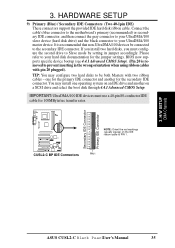
... accordingly. Please refer to prevent inserting in the wrong orientation when using ribbon cables with two ribbon cables - H/W SETUP DCMoAnnCehcatnornsels ASUS CUSL2-C Black PearlUser's Manual 35 It is removed to your UltraDMA/100 master device. TIP: You may install one for the secondary...cable. You may configure two hard disks to be connected to your hard disk documentation for 100MByte/sec transfer rates. ® CUSL2-C BP CUSL2-C BP IDE Connectors NOTE: Orient the red markings (usually zigzag) on a SCSI drive and select the boot disk through 4.4.1 Advanced CMOS...
... accordingly. Please refer to prevent inserting in the wrong orientation when using ribbon cables with two ribbon cables - H/W SETUP DCMoAnnCehcatnornsels ASUS CUSL2-C Black PearlUser's Manual 35 It is removed to your UltraDMA/100 master device. TIP: You may install one for the secondary...cable. You may configure two hard disks to be connected to your hard disk documentation for 100MByte/sec transfer rates. ® CUSL2-C BP CUSL2-C BP IDE Connectors NOTE: Orient the red markings (usually zigzag) on a SCSI drive and select the boot disk through 4.4.1 Advanced CMOS...

CUSL2-C BP User Manual
Page 36
...red wire should be positive, while the black should be read directly from the ASUS iPanel or monitored using a utility such as ASUS PC Probe or Intel LDCM. Rotation +12V GND ® CUSL2-C BP CUSL2-C BP 12-Volt Cooling Fan Power Rotation +12V GND CPU_FAN GND +12V Rotation PWR_FAN CHA_FAN... 36 ASUS CUSL2-C Black PearlUser's Manual Read and write activity by a specially designed fan with rotation signal. Depending on the fan ...
...red wire should be positive, while the black should be read directly from the ASUS iPanel or monitored using a utility such as ASUS PC Probe or Intel LDCM. Rotation +12V GND ® CUSL2-C BP CUSL2-C BP 12-Volt Cooling Fan Power Rotation +12V GND CPU_FAN GND +12V Rotation PWR_FAN CHA_FAN... 36 ASUS CUSL2-C Black PearlUser's Manual Read and write activity by a specially designed fan with rotation signal. Depending on the fan ...

CUSL2-C BP User Manual
Page 37
...for a hard disk drive. VCC NC SCRFET# SCRCLK RFU1 GND NC2 LED NC SCRREST RFU2 SCRUI SCRRES# 1 ® CUSL2-C BP CUSL2-C BP SmartCard Connector ASUS CUSL2-C Black PearlUser's Manual 37 The SmartCard reader accesses data on the memory chip of SmartCards. AFPANEL +5 V IRRX GND IRTX ...+5 V IRRX GND IRTX 3. H/W SETUP Connectors SIR CIR ® CUSL2-C BP CUSL2-C BP Front Panel Connectors IR_CON NC GND NC CIRRX +5VSB Standard Infrared (SIR) Front View Back View IRTX +5V GND (NC) IRRX 13) ASUS SmartCard Connector (10-1 pin SMARTCON) This connector attaches to an optional SmartCard...
...for a hard disk drive. VCC NC SCRFET# SCRCLK RFU1 GND NC2 LED NC SCRREST RFU2 SCRUI SCRRES# 1 ® CUSL2-C BP CUSL2-C BP SmartCard Connector ASUS CUSL2-C Black PearlUser's Manual 37 The SmartCard reader accesses data on the memory chip of SmartCards. AFPANEL +5 V IRRX GND IRTX ...+5 V IRRX GND IRTX 3. H/W SETUP Connectors SIR CIR ® CUSL2-C BP CUSL2-C BP Front Panel Connectors IR_CON NC GND NC CIRRX +5VSB Standard Infrared (SIR) Front View Back View IRTX +5V GND (NC) IRRX 13) ASUS SmartCard Connector (10-1 pin SMARTCON) This connector attaches to an optional SmartCard...

CUSL2-C BP User Manual
Page 38
... designed for chassis intrusion detection. The event can act as LDCM. 3. H/W SETUP Connectors ® CUSL2-C BP CUSL2-C BP Chassis Open Alarm Lead ACHA 38 ASUS CUSL2-C Black PearlUser's Manual When any removable components. SMBus devices communicate by initiating data transfer. ® CUSL2-C CUSL2-C SMBus Connector Ground SMBCLK 1 SMB SMBDATA +5V 15) Chassis Intrusion Lead (2-pin ACHA) This lead...
... designed for chassis intrusion detection. The event can act as LDCM. 3. H/W SETUP Connectors ® CUSL2-C BP CUSL2-C BP Chassis Open Alarm Lead ACHA 38 ASUS CUSL2-C Black PearlUser's Manual When any removable components. SMBus devices communicate by initiating data transfer. ® CUSL2-C CUSL2-C SMBus Connector Ground SMBCLK 1 SMB SMBDATA +5V 15) Chassis Intrusion Lead (2-pin ACHA) This lead...

CUSL2-C BP User Manual
Page 39
...5V standby power. 3. 3. NOTE: For external modems, Wake-On-Ring is enabled (see 7. H/W SETUP Connectors WOR_CON ® CUSL2-C BP CUSL2-C BP Wake-On-Ring Connector Ring# Ground 2 1 ASUS CUSL2-C Black PearlUser's Manual 39 Appendix). The connector powers up the system when a ringup packet or signal is received through the COM...-LAN Connector (3-pin WOL_CON) This connector connects to internal modem cards with a Wake-On-LAN output, such as the ASUS PCI-L101 Ethernet card (see 4.5.1 Power Up Control) and that Wake On LAN or PCI Modem is detected through the LAN card.
...5V standby power. 3. 3. NOTE: For external modems, Wake-On-Ring is enabled (see 7. H/W SETUP Connectors WOR_CON ® CUSL2-C BP CUSL2-C BP Wake-On-Ring Connector Ring# Ground 2 1 ASUS CUSL2-C Black PearlUser's Manual 39 Appendix). The connector powers up the system when a ringup packet or signal is received through the COM...-LAN Connector (3-pin WOL_CON) This connector connects to internal modem cards with a Wake-On-LAN output, such as the ASUS PCI-L101 Ethernet card (see 4.5.1 Power Up Control) and that Wake On LAN or PCI Modem is detected through the LAN card.

CUSL2-C BP User Manual
Page 40
3. USBPWR USBP2USBP2+ GND GND USBP5+ USBP5USBPWR ® CUSL2-C BP CUSL2-C BP USB Headers USB2 1 USB56 19) Power Supply Thermal Sensor Connector (2-pin JTPWR) If you have a power supply with thermal monitoring, connect its thermal sensor cable ... cables from the provided 2-port USB connector set to the two midboard 5-pin USB headers and mount the USB connector set to this connector. ® CUSL2-C BP CUSL2-C BP Thermal Sensor Connector JTPWR Power Supply Thermal Sensor 40 ASUS CUSL2-C Black PearlUser's Manual H/W SETUP Connectors 3.
3. USBPWR USBP2USBP2+ GND GND USBP5+ USBP5USBPWR ® CUSL2-C BP CUSL2-C BP USB Headers USB2 1 USB56 19) Power Supply Thermal Sensor Connector (2-pin JTPWR) If you have a power supply with thermal monitoring, connect its thermal sensor cable ... cables from the provided 2-port USB connector set to the two midboard 5-pin USB headers and mount the USB connector set to this connector. ® CUSL2-C BP CUSL2-C BP Thermal Sensor Connector JTPWR Power Supply Thermal Sensor 40 ASUS CUSL2-C Black PearlUser's Manual H/W SETUP Connectors 3.

CUSL2-C BP User Manual
Page 41
H/W SETUP Connectors ASUS CUSL2-C Black PearlUser's Manual 41 The plug from the power supply will only insert in powering up if your power supply is inadequate. HARDWARE SETUP 20) ... firmly making sure that your ATX power supply must supply at least 10mA (750mA recommended) on the +5-volt lead and at least 750mA +5VSB. ® CUSL2-C BP CUSL2-C BP ATX Power Connector +3.3 Volts -12.0 Volts Ground Power Supply On Ground Ground Ground -5.0 Volts +5.0 Volts +5.0 Volts +3.3 Volts +3.3 Volts Ground +5.0 Volts Ground +5.0 Volts Ground Power Good...
H/W SETUP Connectors ASUS CUSL2-C Black PearlUser's Manual 41 The plug from the power supply will only insert in powering up if your power supply is inadequate. HARDWARE SETUP 20) ... firmly making sure that your ATX power supply must supply at least 10mA (750mA recommended) on the +5-volt lead and at least 750mA +5VSB. ® CUSL2-C BP CUSL2-C BP ATX Power Connector +3.3 Volts -12.0 Volts Ground Power Supply On Ground Ground Ground -5.0 Volts +5.0 Volts +5.0 Volts +3.3 Volts +3.3 Volts Ground +5.0 Volts Ground +5.0 Volts Ground Power Good...

CUSL2-C BP User Manual
Page 42
... turn off . HARDWARE SETUP The following is in use. The system power LED shows the status of the system's power supply. 42 ASUS CUSL2-C Black PearlUser's Manual H/W SETUP Connectors ® CUSL2-C BP CUSL2-C BP System Panel Connectors Message LED SMI Lead Reset SW ATX Power Switch* * Requires an ATX power supply. 21) System Power LED Lead...
... turn off . HARDWARE SETUP The following is in use. The system power LED shows the status of the system's power supply. 42 ASUS CUSL2-C Black PearlUser's Manual H/W SETUP Connectors ® CUSL2-C BP CUSL2-C BP System Panel Connectors Message LED SMI Lead Reset SW ATX Power Switch* * Requires an ATX power supply. 21) System Power LED Lead...


