

CUR-DLSR User Manual
Page 2
...FOR INFORMATIONAL USE ONLY, AND ARE SUBJECT TO CHANGE AT ANY TIME WITHOUT NOTICE, AND SHOULD NOT BE CONSTRUED AS A COMMITMENT BY ASUS. ASUS ASSUMES NO RESPONSIBILITY OR LIABILITY FOR ANY ERRORS OR INACCURACIES THAT MAY APPEAR IN THIS MANUAL, INCLUDING THE PRODUCTS AND SOFTWARE DESCRIBED IN IT... or may be reproduced, transmitted, transcribed, stored in a retrieval system, or translated into any language in any form or by ASUS; Product Name: ASUS CUR-DLSR Manual Revision: 1.03 E630 Release Date: March 2001 2 ASUS CUR-DLSR User's Manual Copyright © 2001 ASUSTeK COMPUTER INC.
...FOR INFORMATIONAL USE ONLY, AND ARE SUBJECT TO CHANGE AT ANY TIME WITHOUT NOTICE, AND SHOULD NOT BE CONSTRUED AS A COMMITMENT BY ASUS. ASUS ASSUMES NO RESPONSIBILITY OR LIABILITY FOR ANY ERRORS OR INACCURACIES THAT MAY APPEAR IN THIS MANUAL, INCLUDING THE PRODUCTS AND SOFTWARE DESCRIBED IN IT... or may be reproduced, transmitted, transcribed, stored in a retrieval system, or translated into any language in any form or by ASUS; Product Name: ASUS CUR-DLSR Manual Revision: 1.03 E630 Release Date: March 2001 2 ASUS CUR-DLSR User's Manual Copyright © 2001 ASUSTeK COMPUTER INC.
CUR-DLSR User Manual
Page 3
...) Notebook (Tel): +886-2-2890-7122 (English) Desktop/Server (Tel):+886-2-2890-7123 (English) Fax: +886-2-2893-7775 Email: tsd@asus.com.tw WWW: www.asus.com.tw FTP: ftp.asus.com.tw/pub/ASUS ASUS COMPUTER INTERNATIONAL (America) Marketing Address: 6737 Mowry Avenue, Mowry Business Center, Building 2 Newark, CA 94560, USA Fax: +1-510-608-4555... Fax: +49-2102-9599-11 Support (Email): www.asuscom.de/de/support (for online support) WWW: www.asuscom.de FTP: ftp.asuscom.de/pub/ASUSCOM ASUS CUR-DLSR User's Manual 3
...) Notebook (Tel): +886-2-2890-7122 (English) Desktop/Server (Tel):+886-2-2890-7123 (English) Fax: +886-2-2893-7775 Email: tsd@asus.com.tw WWW: www.asus.com.tw FTP: ftp.asus.com.tw/pub/ASUS ASUS COMPUTER INTERNATIONAL (America) Marketing Address: 6737 Mowry Avenue, Mowry Business Center, Building 2 Newark, CA 94560, USA Fax: +1-510-608-4555... Fax: +49-2102-9599-11 Support (Email): www.asuscom.de/de/support (for online support) WWW: www.asuscom.de FTP: ftp.asuscom.de/pub/ASUSCOM ASUS CUR-DLSR User's Manual 3
CUR-DLSR User Manual
Page 4
HARDWARE SETUP 14 3.1 CUR-DLSR Motherboard Layout 14 3.2 Layout Contents 15 3.3 Hardware Setup Procedure 16 3.4 Motherboard Settings 16 3.5 System Memory 19 ... 25 3.8 Connectors 27 3.8.1 External Connectors 27 3.8.2 Internal Connectors 29 3.9 Starting Up the First Time 39 4 ASUS CUR-DLSR User's Manual INTRODUCTION 7 1.1 How This Manual Is Organized 7 1.2 Item Checklist 7 2. FEATURES 8 2.1 ASUS CUR-DLSR Motherboard 8 2.1.1 Specifications 8 2.1.2 Performance 10 2.1.3 Intelligence 11 2.2 CUR-DLSR Motherboard Components 12 2.2.1 Component Locations 13 3. CONTENTS 1.
HARDWARE SETUP 14 3.1 CUR-DLSR Motherboard Layout 14 3.2 Layout Contents 15 3.3 Hardware Setup Procedure 16 3.4 Motherboard Settings 16 3.5 System Memory 19 ... 25 3.8 Connectors 27 3.8.1 External Connectors 27 3.8.2 Internal Connectors 29 3.9 Starting Up the First Time 39 4 ASUS CUR-DLSR User's Manual INTRODUCTION 7 1.1 How This Manual Is Organized 7 1.2 Item Checklist 7 2. FEATURES 8 2.1 ASUS CUR-DLSR Motherboard 8 2.1.1 Specifications 8 2.1.2 Performance 10 2.1.3 Intelligence 11 2.2 CUR-DLSR Motherboard Components 12 2.2.1 Component Locations 13 3. CONTENTS 1.
CUR-DLSR User Manual
Page 5
OS DRIVER INSTALLATION 71 (Turn to page 71 for detailed contents on OS Drivers) ASUS CUR-DLSR User's Manual 5 CONTENTS 4. BIOS SETUP 41 4.1 Managing and Updating Your BIOS 41 4.1.1 Upon First Use of the Computer System 41 4.1.2 Updating BIOS Procedures 43 4.2 BIOS ...
OS DRIVER INSTALLATION 71 (Turn to page 71 for detailed contents on OS Drivers) ASUS CUR-DLSR User's Manual 5 CONTENTS 4. BIOS SETUP 41 4.1 Managing and Updating Your BIOS 41 4.1.1 Upon First Use of the Computer System 41 4.1.2 Updating BIOS Procedures 43 4.2 BIOS ...
CUR-DLSR User Manual
Page 6
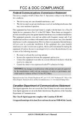
...: Office of the FCC Rules. Government Printing Office. Cet appareil numérique de la classe B est conforme à la norme NMB-003 du Canada. 6 ASUS CUR-DLSR User's Manual Any changes or modifications to this equipment does cause harmful interference to radio or television reception, which the receiver is connected. • Consult...
...: Office of the FCC Rules. Government Printing Office. Cet appareil numérique de la classe B est conforme à la norme NMB-003 du Canada. 6 ASUS CUR-DLSR User's Manual Any changes or modifications to this equipment does cause harmful interference to radio or television reception, which the receiver is connected. • Consult...

CUR-DLSR User Manual
Page 7
...Product information and specifications Instructions on setting up the motherboard. If you discover damaged or missing items, contact your retailer. (1) ASUS Motherboard (1) I/O Shield (1) Ribbon cable for master and slave IDE drives (1) 68-pin LVD SCSI ribbon cable for Ultra160 devices...drivers and utilities (1) User's Manual Optional Items (1) PGA370 CPU Terminator (required when installing only one CPU) ASUS CUR-DLSR User's Manual 7 SOFTWARE REFERENCE 7. INTRODUCTION 1.1 How This Manual Is Organized This manual is complete. HARDWARE SETUP 4. INTRODUCTION Manual / Checklist ...
...Product information and specifications Instructions on setting up the motherboard. If you discover damaged or missing items, contact your retailer. (1) ASUS Motherboard (1) I/O Shield (1) Ribbon cable for master and slave IDE drives (1) 68-pin LVD SCSI ribbon cable for Ultra160 devices...drivers and utilities (1) User's Manual Optional Items (1) PGA370 CPU Terminator (required when installing only one CPU) ASUS CUR-DLSR User's Manual 7 SOFTWARE REFERENCE 7. INTRODUCTION 1.1 How This Manual Is Organized This manual is complete. HARDWARE SETUP 4. INTRODUCTION Manual / Checklist ...

CUR-DLSR User Manual
Page 8
...LSI 53C1010-33 Ultra160 64-bit (33MHz) dual-channel SCSI controller supports up to physically transport commands and information between SMBus devices. 8 ASUS CUR-DLSR User's Manual Supports PIO Modes 3 and 4 IDE devices, such as DVD-ROM, CD-ROM, CD-R/RW, LS-120, and Tape...: Supports dual Socket 370-based Intel Pentium III processors running up to optimize available space without sacrificing performance. FEATURES 2.1 ASUS CUR-DLSR Motherboard The ASUS CUR-DLSR motherboard is used to 30 SCSI devices. • Standard IDE Support: Comes with an onboard PCI Bus Master IDE controller...
...LSI 53C1010-33 Ultra160 64-bit (33MHz) dual-channel SCSI controller supports up to physically transport commands and information between SMBus devices. 8 ASUS CUR-DLSR User's Manual Supports PIO Modes 3 and 4 IDE devices, such as DVD-ROM, CD-ROM, CD-R/RW, LS-120, and Tape...: Supports dual Socket 370-based Intel Pentium III processors running up to optimize available space without sacrificing performance. FEATURES 2.1 ASUS CUR-DLSR Motherboard The ASUS CUR-DLSR motherboard is used to 30 SCSI devices. • Standard IDE Support: Comes with an onboard PCI Bus Master IDE controller...

CUR-DLSR User Manual
Page 9
... CPU and systerm voltages, temperatures, and fan status through the onboard hardware ASUS ASIC. • Enhanced ACPI: Programmable BIOS (Flash EEPROM), offering enhanced ACPI for Windows 2000 compatibility, and autodetection of most devices for virtually automatic setup. • CPU Throttling: This feature protects the CPU from overheating. 2. FEATURES Specifications ASUS CUR-DLSR User's Manual 9
... CPU and systerm voltages, temperatures, and fan status through the onboard hardware ASUS ASIC. • Enhanced ACPI: Programmable BIOS (Flash EEPROM), offering enhanced ACPI for Windows 2000 compatibility, and autodetection of most devices for virtually automatic setup. • CPU Throttling: This feature protects the CPU from overheating. 2. FEATURES Specifications ASUS CUR-DLSR User's Manual 9
CUR-DLSR User Manual
Page 10
... Both the Microsoft WHQL and hardware levels of ACPI, use an ACPI-supported OS, such as required by PC 99. 10 ASUS CUR-DLSR User's Manual Ultra160 is also implemented on the following high-level goals: support for Plug and Play compatibility and power management for ...older SCSI devices are based on all system components, and 32-bit device drivers and installation procedures for configuring and managing all ASUS smart series motherboards. FEATURES 2.1.2 Performance • UltraPerformance: Onboard Ultra160 dual channel SCSI controller with slower SCSI devices so that ...
... Both the Microsoft WHQL and hardware levels of ACPI, use an ACPI-supported OS, such as required by PC 99. 10 ASUS CUR-DLSR User's Manual Ultra160 is also implemented on the following high-level goals: support for Plug and Play compatibility and power management for ...older SCSI devices are based on all system components, and 32-bit device drivers and installation procedures for configuring and managing all ASUS smart series motherboards. FEATURES 2.1.2 Performance • UltraPerformance: Onboard Ultra160 dual channel SCSI controller with slower SCSI devices so that ...
CUR-DLSR User Manual
Page 11
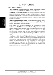
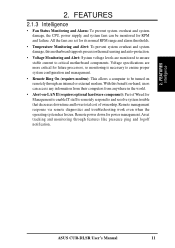
... Monitoring and Alert: System voltage levels are more critical for Management to enable IT staff to remotely respond to be monitored for RPM and failure. ASUS CUR-DLSR User's Manual 11 FEATURES 2.1.3 Intelligence • Fan Status Monitoring and Alarm: To prevent system overheat and system damage, the CPU, power supply, and system fans...
... Monitoring and Alert: System voltage levels are more critical for Management to enable IT staff to remotely respond to be monitored for RPM and failure. ASUS CUR-DLSR User's Manual 11 FEATURES 2.1.3 Intelligence • Fan Status Monitoring and Alarm: To prevent system overheat and system damage, the CPU, power supply, and system fans...
CUR-DLSR User Manual
Page 12
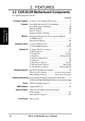
...Flash ROM 18 Super I/O Chipset 14 Integrated Graphics Controller 17 Memory Maximum 4GB support for locations. FEATURES 2.2 CUR-DLSR Motherboard Components See opposite page for PC133 registered SDRAM (4) DIMM Sockets 5 Onboard VGA Memory 16 Expansion Slots (1) 64...ASUS ASIC) ......... 1 (4) Fan Power & Speed Monitoring Connectors (see layout on next page) Power ATX Power Supply Connector 4 CMOS Battery Lithium CR2032 3V 19 Special Feature LSI 64-bit (66/33MHz) Ultra160 dual-channel SCSI controller 12 Onboard SCSI Connectors 8, 9 Form Factor Full-size ATX 12 ASUS CUR-DLSR...
...Flash ROM 18 Super I/O Chipset 14 Integrated Graphics Controller 17 Memory Maximum 4GB support for locations. FEATURES 2.2 CUR-DLSR Motherboard Components See opposite page for PC133 registered SDRAM (4) DIMM Sockets 5 Onboard VGA Memory 16 Expansion Slots (1) 64...ASUS ASIC) ......... 1 (4) Fan Power & Speed Monitoring Connectors (see layout on next page) Power ATX Power Supply Connector 4 CMOS Battery Lithium CR2032 3V 19 Special Feature LSI 64-bit (66/33MHz) Ultra160 dual-channel SCSI controller 12 Onboard SCSI Connectors 8, 9 Form Factor Full-size ATX 12 ASUS CUR-DLSR...

CUR-DLSR User Manual
Page 15
... Ultra160 SCSI Connectors (two 68-pin) p. 34 CPU and Chassis Fan Connectors (four 3-pin) p. 34 Chassis Open Alarm Lead (4-pin) p. 35 SMBus Connector (5-1 pins) p. 35 ASUS Ser Management Card Connectors p. 36 Serial Port 2 (9-pin male) p. 36 Panel 2 Connector (8-pin) p. 37 Power Supply Connector (2-pin) p. 37 Power Button Connector (2-pin) p. 38 NIC... (2-pin) p. 38 System Power LED Lead (3-1 pin) p. 38 Non-Mask Interrupt Switch (2-pin) p. 38 System Warning Speaker Connector (4-pin) p. 38 IDE/SCSI Activity LED (2-pin) ASUS CUR-DLSR User's Manual 15 3. H/W SETUP Layout Contents 3.
... Ultra160 SCSI Connectors (two 68-pin) p. 34 CPU and Chassis Fan Connectors (four 3-pin) p. 34 Chassis Open Alarm Lead (4-pin) p. 35 SMBus Connector (5-1 pins) p. 35 ASUS Ser Management Card Connectors p. 36 Serial Port 2 (9-pin male) p. 36 Panel 2 Connector (8-pin) p. 37 Power Supply Connector (2-pin) p. 37 Power Button Connector (2-pin) p. 38 NIC... (2-pin) p. 38 System Power LED Lead (3-1 pin) p. 38 Non-Mask Interrupt Switch (2-pin) p. 38 System Warning Speaker Connector (4-pin) p. 38 IDE/SCSI Activity LED (2-pin) ASUS CUR-DLSR User's Manual 15 3. H/W SETUP Layout Contents 3.

CUR-DLSR User Manual
Page 16
... is switched off or the power cord is detached from the power supply. Unplug the computer when working on your computer: 1. H/W SETUP Motherboard Settings 16 ASUS CUR-DLSR User's Manual Check motherboard settings 2. 3. Whenever you how to the motherboard, peripherals, and/or components. 3. HARDWARE SETUP 3.3 Hardware Setup Procedure Complete the following steps before...
... is switched off or the power cord is detached from the power supply. Unplug the computer when working on your computer: 1. H/W SETUP Motherboard Settings 16 ASUS CUR-DLSR User's Manual Check motherboard settings 2. 3. Whenever you how to the motherboard, peripherals, and/or components. 3. HARDWARE SETUP 3.3 Hardware Setup Procedure Complete the following steps before...

CUR-DLSR User Manual
Page 17
...must be stable. ASUS CUR-DLSR User's Manual 17 H/W SETUP Motherboard Settings 3. Reserved 4. ON ON ON 12345678 2.0x ON 12345678 2.5x ON 12345678 3.0x ON 12345678 3.5x ON 12345678 4.0x ON 12345678 4.5x ON 12345678 5.0x ON 12345678 5.5x ON 12345678 6.0x ON CUR-DLSR CUR-DLSR CPU : BUS... figure below shows all DIP switches on a DIP switch represents the ON or OFF position. Reserved 5. The white block on the CUR-DLSR motherboard and their corresponding settings. 1) CPU Core Bus Frequency Multiple (Switches 5-8) This option sets the frequency multiple between the CPU's ...
...must be stable. ASUS CUR-DLSR User's Manual 17 H/W SETUP Motherboard Settings 3. Reserved 4. ON ON ON 12345678 2.0x ON 12345678 2.5x ON 12345678 3.0x ON 12345678 3.5x ON 12345678 4.0x ON 12345678 4.5x ON 12345678 5.0x ON 12345678 5.5x ON 12345678 6.0x ON CUR-DLSR CUR-DLSR CPU : BUS... figure below shows all DIP switches on a DIP switch represents the ON or OFF position. Reserved 5. The white block on the CUR-DLSR motherboard and their corresponding settings. 1) CPU Core Bus Frequency Multiple (Switches 5-8) This option sets the frequency multiple between the CPU's ...
CUR-DLSR User Manual
Page 18
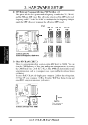
...17.25MHz 142.00MHz 35.50MHz 71.00MHz 17.75MHz 3) Clear RTC RAM (CLRTC) These two solder points allow you to Clear CMOS 18 ASUS CUR-DLSR User's Manual You can clear the CMOS memory of the CPU's External frequency (or BUS Clock). This allows the selection of date, time..., and system setup parameters by the onboard button cell battery. H/W SETUP Motherboard Settings CUR-DLSR CUR-DLSR Clear RTC RAM R266 CLRTC Short solder points to clear the RTC RAM in CMOS. HARDWARE SETUP 2) CPU External Frequency Selection (FSW Switches 1-5) ...
...17.25MHz 142.00MHz 35.50MHz 71.00MHz 17.75MHz 3) Clear RTC RAM (CLRTC) These two solder points allow you to Clear CMOS 18 ASUS CUR-DLSR User's Manual You can clear the CMOS memory of the CPU's External frequency (or BUS Clock). This allows the selection of date, time..., and system setup parameters by the onboard button cell battery. H/W SETUP Motherboard Settings CUR-DLSR CUR-DLSR Clear RTC RAM R266 CLRTC Short solder points to clear the RTC RAM in CMOS. HARDWARE SETUP 2) CPU External Frequency Selection (FSW Switches 1-5) ...
CUR-DLSR User Manual
Page 19
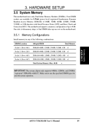
3. H/W SETUP System Memory ASUS CUR-DLSR User's Manual 19 Four DIMM sockets are available for smooth system operation. 3. One side (with memory chips) of the DIMM takes up to use the ...
3. H/W SETUP System Memory ASUS CUR-DLSR User's Manual 19 Four DIMM sockets are available for smooth system operation. 3. One side (with memory chips) of the DIMM takes up to use the ...
CUR-DLSR User Manual
Page 20
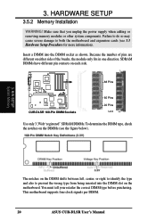
... also to both the motherboard and expansion cards (see the figure below). 3. SDRAM DIMMs have different pin contacts on each side. 88 Pins CUR-DLSR CUR-DLSR 168-Pin DIMM Sockets 60 Pins 20 Pins Lock Use only 3.3Volt "registered" SDRAM DIMMs. To determine the DIMM type, check the notches... to prevent the wrong type from being inserted into the DIMM socket as shown. This motherboard supports four clock signals per DIMM. 20 ASUS CUR-DLSR User's Manual You must tell your retailer the correct DIMM type before purchasing. Make sure that you unplug the power supply when adding ...
... also to both the motherboard and expansion cards (see the figure below). 3. SDRAM DIMMs have different pin contacts on each side. 88 Pins CUR-DLSR CUR-DLSR 168-Pin DIMM Sockets 60 Pins 20 Pins Lock Use only 3.3Volt "registered" SDRAM DIMMs. To determine the DIMM type, check the notches... to prevent the wrong type from being inserted into the DIMM socket as shown. This motherboard supports four clock signals per DIMM. 20 ASUS CUR-DLSR User's Manual You must tell your retailer the correct DIMM type before purchasing. Make sure that you unplug the power supply when adding ...
CUR-DLSR User Manual
Page 21
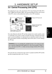
3. Gold Arrow Socket 370 Pentium III Silver Arrow CUR-DLSR CUR-DLSR Socket 370 Socket 370 Terminator (Use when only one corner) to help you identify the proper orientation and enable you must use a specially designed heatsink ... a gold mark on the motherboard and the correct CPU orientation. Failure to do so will cause the CPU to damage the CPU pins. H/W SETUP CPU ASUS CUR-DLSR User's Manual 21 The following illustration shows the location of the CPU and terminator with the corresponding corner on how to correctly install them. WARNING...
3. Gold Arrow Socket 370 Pentium III Silver Arrow CUR-DLSR CUR-DLSR Socket 370 Socket 370 Terminator (Use when only one corner) to help you identify the proper orientation and enable you must use a specially designed heatsink ... a gold mark on the motherboard and the correct CPU orientation. Failure to do so will cause the CPU to damage the CPU pins. H/W SETUP CPU ASUS CUR-DLSR User's Manual 21 The following illustration shows the location of the CPU and terminator with the corresponding corner on how to correctly install them. WARNING...
CUR-DLSR User Manual
Page 22
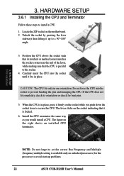
... the CPU. Carefuly insert the CPU into the socket to the socket. 4. Do not force the CPU into the socket until it up problems. 22 ASUS CUR-DLSR User's Manual Install the CPU terminator the same way as you push down the socket lever to install a CPU. 1.
... the CPU. Carefuly insert the CPU into the socket to the socket. 4. Do not force the CPU into the socket until it up problems. 22 ASUS CUR-DLSR User's Manual Install the CPU terminator the same way as you push down the socket lever to install a CPU. 1.

CUR-DLSR User Manual
Page 23
Retaining Clip for the Tab on top of the installed CPU and hook one end of the Socket 3. ASUS CUR-DLSR User's Manual 23 Use a flat screwdriver to hook the other end of the retaining clip to the protruding tab at the Back of the retaining ...
Retaining Clip for the Tab on top of the installed CPU and hook one end of the Socket 3. ASUS CUR-DLSR User's Manual 23 Use a flat screwdriver to hook the other end of the retaining clip to the protruding tab at the Back of the retaining ...


