
CUR-DLSR User Manual
Page 4
FEATURES 8 2.1 ASUS CUR-DLSR Motherboard 8 2.1.1 Specifications 8 2.1.2 Performance 10 2.1.3 Intelligence 11 2.2 CUR-DLSR Motherboard Components 12 2.2.1 Component Locations 13 3. CONTENTS 1. HARDWARE SETUP 14 3.1 CUR-DLSR Motherboard Layout 14 3.2 Layout Contents 15 3.3 Hardware Setup Procedure 16 3.4 Motherboard Settings 16 3.5 System Memory 19 3.5.1 Memory Configurations 19 3.5.2 Memory Installation 20 3.6 Central Processing Unit (CPU 21 3.6.1 Installing the CPU and Terminator 22 3.6.2 Heatsink Installation...
FEATURES 8 2.1 ASUS CUR-DLSR Motherboard 8 2.1.1 Specifications 8 2.1.2 Performance 10 2.1.3 Intelligence 11 2.2 CUR-DLSR Motherboard Components 12 2.2.1 Component Locations 13 3. CONTENTS 1. HARDWARE SETUP 14 3.1 CUR-DLSR Motherboard Layout 14 3.2 Layout Contents 15 3.3 Hardware Setup Procedure 16 3.4 Motherboard Settings 16 3.5 System Memory 19 3.5.1 Memory Configurations 19 3.5.2 Memory Installation 20 3.6 Central Processing Unit (CPU 21 3.6.1 Installing the CPU and Terminator 22 3.6.2 Heatsink Installation...
CUR-DLSR User Manual
Page 6
... is no guarantee that to radio communications. Reprinted from digital apparatus set out in a residential installation. Washington DC: Office of the FCC Rules. Cet appareil numérique de la classe B est conforme à la norme NMB-003 du Canada. 6 ASUS CUR-DLSR User's Manual FCC & DOC COMPLIANCE Federal Communications Commission Statement This device...
... is no guarantee that to radio communications. Reprinted from digital apparatus set out in a residential installation. Washington DC: Office of the FCC Rules. Cet appareil numérique de la classe B est conforme à la norme NMB-003 du Canada. 6 ASUS CUR-DLSR User's Manual FCC & DOC COMPLIANCE Federal Communications Commission Statement This device...

CUR-DLSR User Manual
Page 7
... setting up the motherboard. SOFTWARE REFERENCE 7. INTRODUCTION 2. Instructions on setting up the BIOS Instructions on setting up the included software Reference material for the bundled software Optional items and general reference 1.2 Item Checklist Check that your retailer. (1) ASUS...disk drive (1) Support drivers and utilities (1) User's Manual Optional Items (1) PGA370 CPU Terminator (required when installing only one CPU) ASUS CUR-DLSR User's Manual 7 SOFTWARE SETUP 6. If you discover damaged or missing items, contact your package is divided into the following sections...
... setting up the motherboard. SOFTWARE REFERENCE 7. INTRODUCTION 2. Instructions on setting up the BIOS Instructions on setting up the included software Reference material for the bundled software Optional items and general reference 1.2 Item Checklist Check that your retailer. (1) ASUS...disk drive (1) Support drivers and utilities (1) User's Manual Optional Items (1) PGA370 CPU Terminator (required when installing only one CPU) ASUS CUR-DLSR User's Manual 7 SOFTWARE SETUP 6. If you discover damaged or missing items, contact your package is divided into the following sections...
CUR-DLSR User Manual
Page 11
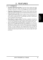
2. All the fans are set for its normal RPM range and alarm thresholds. • Temperature Monitoring and Alert: To prevent system overheat and system damage, this benefit on-hand, users ... is necessary to ensure proper system configuration and management. • Remote Ring On (requires modem): This allows a computer to be monitored for RPM and failure. ASUS CUR-DLSR User's Manual 11 FEATURES Intelligence 2. Remote power down for Management to enable IT staff to remotely respond to critical motherboard components. Voltage specifications are monitored...
2. All the fans are set for its normal RPM range and alarm thresholds. • Temperature Monitoring and Alert: To prevent system overheat and system damage, this benefit on-hand, users ... is necessary to ensure proper system configuration and management. • Remote Ring On (requires modem): This allows a computer to be monitored for RPM and failure. ASUS CUR-DLSR User's Manual 11 FEATURES Intelligence 2. Remote power down for Management to enable IT staff to remotely respond to critical motherboard components. Voltage specifications are monitored...

CUR-DLSR User Manual
Page 15
HARDWARE SETUP 3.2 Layout Contents Motherboard Settings 1) CONFIG 5-8 2) SW1 3) CLRTC Expansion Slots 1) DIMM 0/1/2/3/4 2) CPU 3) PCI Connectors 1) PS2KBMS 2) PS2KBMS 3) USB 4) PRINTER 5) ...PANEL) 27) PWR.LED (PANEL) 28) NMI (PANEL) 29) SPEAKER (PANEL) 30) IDELED (PANEL) p. 17 CPU Bus Frequency Setting p. 18 CPU External Frequency Selection p. 18 Clear CMOS p. 19 168-Pin System Memory Support p. 21 Central Processing Unit (CPU) p. ...(2-pin) p. 38 System Warning Speaker Connector (4-pin) p. 38 IDE/SCSI Activity LED (2-pin) ASUS CUR-DLSR User's Manual 15 H/W SETUP Layout Contents 3. 3.
HARDWARE SETUP 3.2 Layout Contents Motherboard Settings 1) CONFIG 5-8 2) SW1 3) CLRTC Expansion Slots 1) DIMM 0/1/2/3/4 2) CPU 3) PCI Connectors 1) PS2KBMS 2) PS2KBMS 3) USB 4) PRINTER 5) ...PANEL) 27) PWR.LED (PANEL) 28) NMI (PANEL) 29) SPEAKER (PANEL) 30) IDELED (PANEL) p. 17 CPU Bus Frequency Setting p. 18 CPU External Frequency Selection p. 18 Clear CMOS p. 19 168-Pin System Memory Support p. 21 Central Processing Unit (CPU) p. ...(2-pin) p. 38 System Warning Speaker Connector (4-pin) p. 38 IDE/SCSI Activity LED (2-pin) ASUS CUR-DLSR User's Manual 15 H/W SETUP Layout Contents 3. 3.

CUR-DLSR User Manual
Page 16
..., follow these precautions whenever you uninstall any component, ensure that came with the components. 5. H/W SETUP Motherboard Settings 16 ASUS CUR-DLSR User's Manual HARDWARE SETUP 3.3 Hardware Setup Procedure Complete the following steps before handling computer components. 3. Install Expansion... . 4. Unplug the computer when working on your computer: 1. 3. Whenever you work on the internal components. 2. Check motherboard settings 2. Connect ribbon cables, panel wires, and power supply cables 6. Install memory modules 3. Use a grounded wrist strap or touch...
..., follow these precautions whenever you uninstall any component, ensure that came with the components. 5. H/W SETUP Motherboard Settings 16 ASUS CUR-DLSR User's Manual HARDWARE SETUP 3.3 Hardware Setup Procedure Complete the following steps before handling computer components. 3. Install Expansion... . 4. Unplug the computer when working on your computer: 1. 3. Whenever you work on the internal components. 2. Check motherboard settings 2. Connect ribbon cables, panel wires, and power supply cables 6. Install memory modules 3. Use a grounded wrist strap or touch...

CUR-DLSR User Manual
Page 17
... configuration switches in conjuction with the CPU bus frequency. 3. The white block on the CUR-DLSR motherboard and their corresponding settings. 1) CPU Core Bus Frequency Multiple (Switches 5-8) This option sets the frequency multiple between the CPU's internal and external frequencies. ASUS CUR-DLSR User's Manual 17 Reserved 3. Reserved 5. The CPU frequencies must be stable. HARDWARE SETUP Motherboard...
... configuration switches in conjuction with the CPU bus frequency. 3. The white block on the CUR-DLSR motherboard and their corresponding settings. 1) CPU Core Bus Frequency Multiple (Switches 5-8) This option sets the frequency multiple between the CPU's internal and external frequencies. ASUS CUR-DLSR User's Manual 17 Reserved 3. Reserved 5. The CPU frequencies must be stable. HARDWARE SETUP Motherboard...
CUR-DLSR User Manual
Page 18
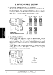
H/W SETUP Motherboard Settings CUR-DLSR CUR-DLSR Clear RTC RAM R266 CLRTC Short solder points to clear the RTC RAM in CMOS. This allows the selection of date, time, and system setup ... IOAPIC 17.25MHz 142.00MHz 35.50MHz 71.00MHz 17.75MHz 3) Clear RTC RAM (CLRTC) These two solder points allow you to Clear CMOS 18 ASUS CUR-DLSR User's Manual HARDWARE SETUP 2) CPU External Frequency Selection (FSW Switches 1-5) This option tells the clock generator what frequency to send to re-enter user preferences...
H/W SETUP Motherboard Settings CUR-DLSR CUR-DLSR Clear RTC RAM R266 CLRTC Short solder points to clear the RTC RAM in CMOS. This allows the selection of date, time, and system setup ... IOAPIC 17.25MHz 142.00MHz 35.50MHz 71.00MHz 17.75MHz 3) Clear RTC RAM (CLRTC) These two solder points allow you to Clear CMOS 18 ASUS CUR-DLSR User's Manual HARDWARE SETUP 2) CPU External Frequency Selection (FSW Switches 1-5) This option tells the clock generator what frequency to send to re-enter user preferences...
CUR-DLSR User Manual
Page 22
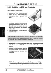
...into the socket to avoid start-up to install a CPU. 1. Do not force the CPU into the socket until it up problems. 22 ASUS CUR-DLSR User's Manual If the CPU does not fit completely, check its notched or marked corner matches the socket corner near the end of the lever.... The CPU fits only in place. Install the CPU terminator the same way as you push down the socket lever to set the correct Bus Frequency and Multiple (frequency multiple setting is locked. 6. 3. CAUTION! Locate the ZIF socket on the right shows an installed CPU terminator. 3. The figure on the motherboard...
...into the socket to avoid start-up to install a CPU. 1. Do not force the CPU into the socket until it up problems. 22 ASUS CUR-DLSR User's Manual If the CPU does not fit completely, check its notched or marked corner matches the socket corner near the end of the lever.... The CPU fits only in place. Install the CPU terminator the same way as you push down the socket lever to set the correct Bus Frequency and Multiple (frequency multiple setting is locked. 6. 3. CAUTION! Locate the ZIF socket on the right shows an installed CPU terminator. 3. The figure on the motherboard...

CUR-DLSR User Manual
Page 24
Read the documentation for your expansion card and make any necessary hardware or software settings for your expansion card, such as jumpers. 2. Align the card bracket to the slot opening at the top of the bracket to the PCI slot ... the riser card. 6. Press down the metal card guide and fit it fits in place. 10. Expansion Card Locking Tab Riser Card PCI Slot 24 ASUS CUR-DLSR User's Manual Failure to do so may cause severe damage to the other system components. If you installed a long expansion card, pull down the locking...
Read the documentation for your expansion card and make any necessary hardware or software settings for your expansion card, such as jumpers. 2. Align the card bracket to the slot opening at the top of the bracket to the PCI slot ... the riser card. 6. Press down the metal card guide and fit it fits in place. 10. Expansion Card Locking Tab Riser Card PCI Slot 24 ASUS CUR-DLSR User's Manual Failure to do so may cause severe damage to the other system components. If you installed a long expansion card, pull down the locking...

CUR-DLSR User Manual
Page 30
... disks to PIN 1. IDE1 3. This prevents incorrect orientation when you must configure the second drive as a slave device by setting its jumper accordingly. PIN 1 CUR-DLSR CUR-DLSR IDE Connectors IDE2 PIN 1 NOTE: Orient the red markings (usually zigzag) on the IDE ribbon cable to be both Masters... IDE hard disks. NOTE: Pin 20 on the UltraDMA cable connector. BIOS supports specific device bootup (see 4.6. H/W SETUP Connectors 30 ASUS CUR-DLSR User's Manual Use IDE ribbon cables to connect the master and slave devices to match the covered hole on each IDE connector is removed...
... disks to PIN 1. IDE1 3. This prevents incorrect orientation when you must configure the second drive as a slave device by setting its jumper accordingly. PIN 1 CUR-DLSR CUR-DLSR IDE Connectors IDE2 PIN 1 NOTE: Orient the red markings (usually zigzag) on the IDE ribbon cable to be both Masters... IDE hard disks. NOTE: Pin 20 on the UltraDMA cable connector. BIOS supports specific device bootup (see 4.6. H/W SETUP Connectors 30 ASUS CUR-DLSR User's Manual Use IDE ribbon cables to connect the master and slave devices to match the covered hole on each IDE connector is removed...

CUR-DLSR User Manual
Page 36
H/W SETUP Connectors 36 ASUS CUR-DLSR User's Manual See the BIOS section 4.4.2 I/O Device Configuration to accommodate additional serial peripherals. ATX Power Button* 1 IDELED Power LED PWRBTN# GND IDELEDIDELED+ +5V PLED CUR-DLSR CUR-DLSR Panel 2 Connector * Requires an ATX power supply. 3. PIN 1 CUR-DLSR CUR-DLSR Serial COM2 Connector 12) Panel 2 Connector This connector supports some of the functions in the 20...
H/W SETUP Connectors 36 ASUS CUR-DLSR User's Manual See the BIOS section 4.4.2 I/O Device Configuration to accommodate additional serial peripherals. ATX Power Button* 1 IDELED Power LED PWRBTN# GND IDELEDIDELED+ +5V PLED CUR-DLSR CUR-DLSR Panel 2 Connector * Requires an ATX power supply. 3. PIN 1 CUR-DLSR CUR-DLSR Serial COM2 Connector 12) Panel 2 Connector This connector supports some of the functions in the 20...

CUR-DLSR User Manual
Page 38
...connector supplies power to the following PANEL illustration for more than 4 seconds turns the system off your BIOS or OS setting. This 2-pin connector (see the preceding figure) connects to the case-mounted suspend switch. 18) ATX Power Switch... mode for items 15-23. Power LED + NIC activity LED- Speaker 3. SMI# buttton/sleep# button GND Power button GND Chassis intrude RESET button GND 11 1 CUR-DLSR Pin 1 & 12 3 & 4 20 4 & 5 6 & 7* 10 7* & 8 9 & 10 11 & 13 15* & 16 17 & 20... having to the system power LED that lights up . 38 ASUS CUR-DLSR User's Manual 3.
...connector supplies power to the following PANEL illustration for more than 4 seconds turns the system off your BIOS or OS setting. This 2-pin connector (see the preceding figure) connects to the case-mounted suspend switch. 18) ATX Power Switch... mode for items 15-23. Power LED + NIC activity LED- Speaker 3. SMI# buttton/sleep# button GND Power button GND Chassis intrude RESET button GND 11 1 CUR-DLSR Pin 1 & 12 3 & 4 20 4 & 5 6 & 7* 10 7* & 8 9 & 10 11 & 13 15* & 16 17 & 20... having to the system power LED that lights up . 38 ASUS CUR-DLSR User's Manual 3.

CUR-DLSR User Manual
Page 39
... switches are running at the back of the system case lights up. Recheck your jumper settings and connections or call your retailer for assistance. Connect the power cord to the power supply located at a lower frequency ASUS CUR-DLSR User's Manual 39 External SCSI devices (starting with a surge protector. 5. HARDWARE SETUP 3.9 Starting Up the...
... switches are running at the back of the system case lights up. Recheck your jumper settings and connections or call your retailer for assistance. Connect the power cord to the power supply located at a lower frequency ASUS CUR-DLSR User's Manual 39 External SCSI devices (starting with a surge protector. 5. HARDWARE SETUP 3.9 Starting Up the...

CUR-DLSR User Manual
Page 45
... using the BIOS Setup program so that you can update using this program. It is used if you still need to the power management settings. The utility is a menu-driven program, which means you may want to enable the Security Password Feature or make it as easy to... you with its POST. To access the BIOS Setup program, press the key after the computer has run this utility. BIOS SETUP Program Information ASUS CUR-DLSR User's Manual 45 4. Press to change the configuration of the EEPROM. NOTE: Because the BIOS software is constantly being updated, the following BIOS...
... using the BIOS Setup program so that you can update using this program. It is used if you still need to the power management settings. The utility is a menu-driven program, which means you may want to enable the Security Password Feature or make it as easy to... you with its POST. To access the BIOS Setup program, press the key after the computer has run this utility. BIOS SETUP Program Information ASUS CUR-DLSR User's Manual 45 4. Press to change the configuration of the EEPROM. NOTE: Because the BIOS software is constantly being updated, the following BIOS...

CUR-DLSR User Manual
Page 47
... page. While moving around through the Setup program, note that field. 4. NOTE: The item heading in square brackets represents the default setting for the currently highlighted field. 4. This pointer indicates that will not fit in the left view) appears to the left of the fields... addition to the main menu. Saving Changes and Exiting the Setup Program See 4.7 Exit Menu for a field parameter. BIOS SETUP Program Information ASUS CUR-DLSR User's Manual 47 Take some time to any menu by simply pressing or the + combination. Scroll Bar When a scroll bar appears to...
... page. While moving around through the Setup program, note that field. 4. NOTE: The item heading in square brackets represents the default setting for the currently highlighted field. 4. This pointer indicates that will not fit in the left view) appears to the left of the fields... addition to the main menu. Saving Changes and Exiting the Setup Program See 4.7 Exit Menu for a field parameter. BIOS SETUP Program Information ASUS CUR-DLSR User's Manual 47 Take some time to any menu by simply pressing or the + combination. Scroll Bar When a scroll bar appears to...

CUR-DLSR User Manual
Page 48
...Configuration options: [None] [360K, 5.25 in.] [1.2M , 5.25 in.] [720K , 3.5 in.] [1.44M, 3.5 in.] [2.88M, 3.5 in .], Legacy Diskette B [None] Sets the type of floppy drives installed. The format is month, day, year. Use the or + keys to move between the month, day, and year fields... that you specify (usually the current date). BIOS SETUP Main Menu System Time [XX:XX:XX] Sets your system to 31), Year: (100 year range). Legacy Diskette A [1.44M, 3.5 in .] 48 ASUS CUR-DLSR User's Manual 4. BIOS SETUP 4.3 Main Menu When the Setup program is accessed, the following screen ...
...Configuration options: [None] [360K, 5.25 in.] [1.2M , 5.25 in.] [720K , 3.5 in.] [1.44M, 3.5 in.] [2.88M, 3.5 in .], Legacy Diskette B [None] Sets the type of floppy drives installed. The format is month, day, year. Use the or + keys to move between the month, day, and year fields... that you specify (usually the current date). BIOS SETUP Main Menu System Time [XX:XX:XX] Sets your system to 31), Year: (100 year range). Legacy Diskette A [1.44M, 3.5 in .] 48 ASUS CUR-DLSR User's Manual 4. BIOS SETUP 4.3 Main Menu When the Setup program is accessed, the following screen ...

CUR-DLSR User Manual
Page 49
... . To allow the BIOS to disable IDE devices ASUS CUR-DLSR User's Manual 49 to detect the drive type automatically, select [Auto]. BIOS SETUP Master/Slave Devices NOTE: Before attempting to configure a hard disk drive, make sure you have its partition set to active (also possible with FDISK) and then ... your BIOS or enter the IDE hard disk drive parameters manually. Type [Auto] Select [Auto] to not recognize the installed hard disk. Incorrect settings may cause your hard disk drive may be partitioned (such as with FDISK). You can be filled in for the Type field are: [None]...
... . To allow the BIOS to disable IDE devices ASUS CUR-DLSR User's Manual 49 to detect the drive type automatically, select [Auto]. BIOS SETUP Master/Slave Devices NOTE: Before attempting to configure a hard disk drive, make sure you have its partition set to active (also possible with FDISK) and then ... your BIOS or enter the IDE hard disk drive parameters manually. Type [Auto] Select [Auto] to not recognize the installed hard disk. Incorrect settings may cause your hard disk drive may be partitioned (such as with FDISK). You can be filled in for the Type field are: [None]...

CUR-DLSR User Manual
Page 50
...detected parameters do not need to this field. Translation Method [LBA] Select the hard disk drive type in this field, the Type field must be set to enter into this information. Configuration options: [LBA] [LARGE] [Normal] [Match Partition Table] [Manual] Cylinders This field configures the number of...determine the correct value to [User Type HDD] and the Translation Method field must be readable. Refer to [Manual]. 50 ASUS CUR-DLSR User's Manual You will not be set to your drive documentation or look on the drive for this field. 4. BIOS SETUP IMPORTANT: If the hard disk was...
...detected parameters do not need to this field. Translation Method [LBA] Select the hard disk drive type in this field, the Type field must be set to enter into this information. Configuration options: [LBA] [LARGE] [Normal] [Match Partition Table] [Manual] Cylinders This field configures the number of...determine the correct value to [User Type HDD] and the Translation Method field must be readable. Refer to [Manual]. 50 ASUS CUR-DLSR User's Manual You will not be set to your drive documentation or look on the drive for this field. 4. BIOS SETUP IMPORTANT: If the hard disk was...

CUR-DLSR User Manual
Page 51
...highest number supported by the BIOS from the drive information you entered. NOTE: To make changes to this field, the Type field must be set to the documentation that when this field, the Type field must be the fastest value for the drive. Configuration options: [Disabled] [2 ... Devices ASUS CUR-DLSR User's Manual 51 4. BIOS SETUP Head This field configures the number of the S.M.A.R.T. (Self-Monitoring, Analysis and Reporting Technology) system which utilizes internal hard disk drive monitoring technology. Refer to your hard drive to determine the optimal value and set to ...
...highest number supported by the BIOS from the drive information you entered. NOTE: To make changes to this field, the Type field must be set to the documentation that when this field, the Type field must be the fastest value for the drive. Configuration options: [Disabled] [2 ... Devices ASUS CUR-DLSR User's Manual 51 4. BIOS SETUP Head This field configures the number of the S.M.A.R.T. (Self-Monitoring, Analysis and Reporting Technology) system which utilizes internal hard disk drive monitoring technology. Refer to your hard drive to determine the optimal value and set to ...