
AW1500-I5 English Manual
Page 2
... identification or explanation and to the owners' benefit, without the express written permission of ASUSTeK COMPUTER INC. ("ASUS"). Product Name: AW1500-S5 Manual Revision: First Edition E1345 Release Date: June 2003 ii ASUS AW1500-S5 IN NO EVENT SHALL ASUS, ITS DIRECTORS, OFFICERS, EMPLOYEES OR AGENTS BE LIABLE FOR ANY INDIRECT, SPECIAL, INCIDENTAL, OR CONSEQUENTIAL DAMAGES (INCLUDING...
... identification or explanation and to the owners' benefit, without the express written permission of ASUSTeK COMPUTER INC. ("ASUS"). Product Name: AW1500-S5 Manual Revision: First Edition E1345 Release Date: June 2003 ii ASUS AW1500-S5 IN NO EVENT SHALL ASUS, ITS DIRECTORS, OFFICERS, EMPLOYEES OR AGENTS BE LIABLE FOR ANY INDIRECT, SPECIAL, INCIDENTAL, OR CONSEQUENTIAL DAMAGES (INCLUDING...

AW1500-I5 English Manual
Page 4
... the receiver is required to an outlet on , the user is encouraged to try to correct the interference by the party responsible for help. iv ASUS AW1500-S5 This class B digital apparatus complies with FCC Rules Part 15. If this unit not expressly approved by one or more of the monitor to the...
... the receiver is required to an outlet on , the user is encouraged to try to correct the interference by the party responsible for help. iv ASUS AW1500-S5 This class B digital apparatus complies with FCC Rules Part 15. If this unit not expressly approved by one or more of the monitor to the...

AW1500-I5 English Manual
Page 6
2.7 Screwless Expansion Card Slot 2-20 2.8 Long Card Support Guide 2-21 2.9 Hard Drive Blower 2-22 2.10 Chassis Fan 2-23 2.11 Connecting Cables 2-24 2.12 SCSI Backplane 2-25 Appendix A: Optional chassis roller-wheel Chassis Roller-wheel Installation A-2 Appendix B: Power Modules Power Supply Specifications A-4 Removing Power Supply Case A-5 Appendix C: Troubleshooting Troubleshooting A-8 vi ASUS AW1500-S5
2.7 Screwless Expansion Card Slot 2-20 2.8 Long Card Support Guide 2-21 2.9 Hard Drive Blower 2-22 2.10 Chassis Fan 2-23 2.11 Connecting Cables 2-24 2.12 SCSI Backplane 2-25 Appendix A: Optional chassis roller-wheel Chassis Roller-wheel Installation A-2 Appendix B: Power Modules Power Supply Specifications A-4 Removing Power Supply Case A-5 Appendix C: Troubleshooting Troubleshooting A-8 vi ASUS AW1500-S5

AW1500-I5 English Manual
Page 8
Dispose of explosion if battery is to the manufacturer's instructions. viii ASUS AW1500-S5 Lithium-Ion Battery Warning CAUTION: Danger of used batteries according to be serviced by the manufacturer. Replace only with the same or equivalent type recommended by a trained personnel only. CD-ROM Drive Safety Warning CLASS 1 LASER PRODUCT • Electrical hazard, do not remove chassis cover. • This equipment is incorrectly replaced.
Dispose of explosion if battery is to the manufacturer's instructions. viii ASUS AW1500-S5 Lithium-Ion Battery Warning CAUTION: Danger of used batteries according to be serviced by the manufacturer. Replace only with the same or equivalent type recommended by a trained personnel only. CD-ROM Drive Safety Warning CLASS 1 LASER PRODUCT • Electrical hazard, do not remove chassis cover. • This equipment is incorrectly replaced.
AW1500-I5 English Manual
Page 10
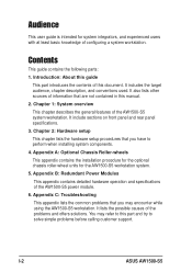
...on front panel and rear panel specifications. 3. Introduction: About this guide This part introduces the contents of the AW1500-S5 power module. 6. Appendix B: Redundant Power Modules This appendix contains detailed hardware operation and specifications of this document. ...AW1500-S5 system workstation. Appendix A: Optional Chassis Roller-wheels This appendix contains the installation procedure for the optional chassis roller-wheel units for system integrators, and experienced users with at least basic knowledge of information that you have to this manual. 2. I-2 ASUS AW1500-S5...
...on front panel and rear panel specifications. 3. Introduction: About this guide This part introduces the contents of the AW1500-S5 power module. 6. Appendix B: Redundant Power Modules This appendix contains detailed hardware operation and specifications of this document. ...AW1500-S5 system workstation. Appendix A: Optional Chassis Roller-wheels This appendix contains the installation procedure for the optional chassis roller-wheel units for system integrators, and experienced users with at least basic knowledge of information that you have to this manual. 2. I-2 ASUS AW1500-S5...

AW1500-I5 English Manual
Page 12
...tray (6 units) 9) AC power cord (1 piece) 10) Support CD that include drivers, utilities and the PC-cillin anti-virus software 11) ASUS PXL-S30 Ultra320 SCSI controller support CD 12) Motherboard user guide 13) System user guide 14) LSI SCSI controller user guide 15) Chassis roller wheels...) Keys for system door x 2 18) Screws and labels Optional: 1) ASUS AS-35 5U rackmount rail kit 2) ASUS PXI-G45 Gb LAN card 3) ASUS AGP8X V9280 graphics card If any of the above items is missing, contact your dealer. LSI MegaRAID 320-1 U320 Single Channel SCSI Card in standard packing; I-4 ASUS AW1500-S5
...tray (6 units) 9) AC power cord (1 piece) 10) Support CD that include drivers, utilities and the PC-cillin anti-virus software 11) ASUS PXL-S30 Ultra320 SCSI controller support CD 12) Motherboard user guide 13) System user guide 14) LSI SCSI controller user guide 15) Chassis roller wheels...) Keys for system door x 2 18) Screws and labels Optional: 1) ASUS AS-35 5U rackmount rail kit 2) ASUS PXI-G45 Gb LAN card 3) ASUS AGP8X V9280 graphics card If any of the above items is missing, contact your dealer. LSI MegaRAID 320-1 U320 Single Channel SCSI Card in standard packing; I-4 ASUS AW1500-S5

AW1500-I5 English Manual
Page 14
...™ processor in a 604-pin socket, and includes the latest I/O, LAN, and video technologies through the chipsets embedded on the motherboard. Motherboard ASUS PP-DLW Chipset North Bridge: Intel® E7505 North Bridge (Placer) South Bridge: Intel® 82801DA South Bridge (ICH4) 64-bit PCI-X...-bit PCI slot: 1 x AGP 8X Pro (1.5V) 1 x PCI-X 133MHz slot 3 x PCI-X 66MHz slots 1 x 32-bit 33MHz 5V PCI slot 1-2 ASUS AW1500-S5 Each RAM supports registered ECC/ unbuffered DDR DIMMs for a total of the workstation's many features: Chassis Pedestal or rackmount 5U with 35º ambient and...
...™ processor in a 604-pin socket, and includes the latest I/O, LAN, and video technologies through the chipsets embedded on the motherboard. Motherboard ASUS PP-DLW Chipset North Bridge: Intel® E7505 North Bridge (Placer) South Bridge: Intel® 82801DA South Bridge (ICH4) 64-bit PCI-X...-bit PCI slot: 1 x AGP 8X Pro (1.5V) 1 x PCI-X 133MHz slot 3 x PCI-X 66MHz slots 1 x 32-bit 33MHz 5V PCI slot 1-2 ASUS AW1500-S5 Each RAM supports registered ECC/ unbuffered DDR DIMMs for a total of the workstation's many features: Chassis Pedestal or rackmount 5U with 35º ambient and...

AW1500-I5 English Manual
Page 16
... remote reboot ASUS SCA SCSI Back Plane Health Monitor: SCSI HDD access and power status with the ASUS SCSI back plane Alert Notification: SNMP® trap,record into NT Event Log and Linux System Log Critical Event Actions: When the system overheats, the system can be shutdown or rebooted depending on setting. 1-4 ASUS AW1500-S5
... remote reboot ASUS SCA SCSI Back Plane Health Monitor: SCSI HDD access and power status with the ASUS SCSI back plane Alert Notification: SNMP® trap,record into NT Event Log and Linux System Log Critical Event Actions: When the system overheats, the system can be shutdown or rebooted depending on setting. 1-4 ASUS AW1500-S5

AW1500-I5 English Manual
Page 18
... Lock Line-Out 6 Full-Length Slots You may secure the chassis lock with an additional padlock or other security device for added server system security. 1-6 ASUS AW1500-S5 1.3 Rear Panel Features The server rear panel includes the connectors, the system devices, a chassis lock and six full-length expansion cards slot.
... Lock Line-Out 6 Full-Length Slots You may secure the chassis lock with an additional padlock or other security device for added server system security. 1-6 ASUS AW1500-S5 1.3 Rear Panel Features The server rear panel includes the connectors, the system devices, a chassis lock and six full-length expansion cards slot.

AW1500-I5 English Manual
Page 20
Icon LED Display Description Green HDD connected and Power status is enabled with HDD rebuilding function. 1-8 ASUS AW1500-S5 Tolerant Enclosure 1 2 3 4 Only RAID cards with SAF-TE feature is good 1 Drive Status LED Red HDD Fail Red blinking HDD rebuilding (RAID card SAF-TE* ... HW monitor event *SCSI Access Fault - 1.5 LED Table The following table describes the LED display found on the front panel and rear panel of the AW1500-S5 server system.
Icon LED Display Description Green HDD connected and Power status is enabled with HDD rebuilding function. 1-8 ASUS AW1500-S5 Tolerant Enclosure 1 2 3 4 Only RAID cards with SAF-TE feature is good 1 Drive Status LED Red HDD Fail Red blinking HDD rebuilding (RAID card SAF-TE* ... HW monitor event *SCSI Access Fault - 1.5 LED Table The following table describes the LED display found on the front panel and rear panel of the AW1500-S5 server system.

AW1500-I5 English Manual
Page 22
The side chassis cover is designed for about half an inch. 3. Release the cover from the chassis. 2-2 ASUS AW1500-S5 Slide the chassis cover for easy assembly and disassembly, making the installation of internal components very convenient. 2.1.1 Removing the chassis cover 1. 2.1 Removing and installing chassis cover The chassis is held by two large thumb screws. Loosen the screws. 2.
The side chassis cover is designed for about half an inch. 3. Release the cover from the chassis. 2-2 ASUS AW1500-S5 Slide the chassis cover for easy assembly and disassembly, making the installation of internal components very convenient. 2.1.1 Removing the chassis cover 1. 2.1 Removing and installing chassis cover The chassis is held by two large thumb screws. Loosen the screws. 2.

AW1500-I5 English Manual
Page 24
... may cause you place it . 2.2 Motherboard placement Before you install the motherboard, study the configuration of your chassis to do so may damage the motherboard. 2-4 ASUS AW1500-S5 Placement direction When installing the motherboard, make sure that you physical injury and damage motherboard components. The PP-DLW uses the extended ATX form factor...
... may cause you place it . 2.2 Motherboard placement Before you install the motherboard, study the configuration of your chassis to do so may damage the motherboard. 2-4 ASUS AW1500-S5 Placement direction When installing the motherboard, make sure that you physical injury and damage motherboard components. The PP-DLW uses the extended ATX form factor...

AW1500-I5 English Manual
Page 26
... in completely. 2. Make sure that it firmly on the motherboard. Carefully insert the CPU into the socket to indicate that the socket lever is locked. 2-6 ASUS AW1500-S5 2.3.2 Installing the CPU If you push down the socket lever to at least 115° angle.
... in completely. 2. Make sure that it firmly on the motherboard. Carefully insert the CPU into the socket to indicate that the socket lever is locked. 2-6 ASUS AW1500-S5 2.3.2 Installing the CPU If you push down the socket lever to at least 115° angle.

AW1500-I5 English Manual
Page 28
... assembly is in place, connect the fan cable to install two CPUs, repeat the same steps for the second CPU heatsink and fan assembly cable. 2-8 ASUS AW1500-S5 Don't forget to plug the fan cable. 5. CPU Socket 1 FAN connector System Fan Connector CPU Socket 2 FAN connector 6. 3. When the heatsink and fan assembly is...
... assembly is in place, connect the fan cable to install two CPUs, repeat the same steps for the second CPU heatsink and fan assembly cable. 2-8 ASUS AW1500-S5 Don't forget to plug the fan cable. 5. CPU Socket 1 FAN connector System Fan Connector CPU Socket 2 FAN connector 6. 3. When the heatsink and fan assembly is...

AW1500-I5 English Manual
Page 30
The same rule applies to use only the specified DIMM types for stable system operation. 2-10 ASUS AW1500-S5 2.4.2 Memory Configurations The motherboard supports system memory of 512MB module into DDRA2. The following table lists the DIMM socket pairs and the memory modules that ...
The same rule applies to use only the specified DIMM types for stable system operation. 2-10 ASUS AW1500-S5 2.4.2 Memory Configurations The motherboard supports system memory of 512MB module into DDRA2. The following table lists the DIMM socket pairs and the memory modules that ...

AW1500-I5 English Manual
Page 32
2.5 Fixed Device Bays 2.5.1 Overview The fixed device bay are available for device placement convenience. An IDE DVD-ROM drive is installed on the uppermost bay and two free bays are cinched by screwless locks for installation of additional storage devices like optical disc drives or tape drives. Front door bezel Screwless fixed device bay locks 2-12 ASUS AW1500-S5
2.5 Fixed Device Bays 2.5.1 Overview The fixed device bay are available for device placement convenience. An IDE DVD-ROM drive is installed on the uppermost bay and two free bays are cinched by screwless locks for installation of additional storage devices like optical disc drives or tape drives. Front door bezel Screwless fixed device bay locks 2-12 ASUS AW1500-S5

AW1500-I5 English Manual
Page 34
3. Do not use too much force when installing or removing items. 4. Remove the appropriate metallic bay panel cover of the bay slot you want to detach the hooked tabs from the left side of the front panel. Take caution in removing the front panel cover. Use thumbs or a flat-head screw driver to install your device. 2-14 ASUS AW1500-S5
3. Do not use too much force when installing or removing items. 4. Remove the appropriate metallic bay panel cover of the bay slot you want to detach the hooked tabs from the left side of the front panel. Take caution in removing the front panel cover. Use thumbs or a flat-head screw driver to install your device. 2-14 ASUS AW1500-S5
AW1500-I5 English Manual
Page 36
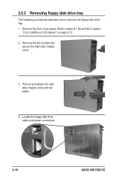
Pull out and detach the right side chassis cover and set aside. 4. Remove the front cover panel. Perform steps #1, #2 and #3 in section "2.5.2 Installing a 5.25 device" on page 2-13. 2. Locate the floppy disk drive cable and power connectors. 2-16 ASUS AW1500-S5 2.5.3 Removing floppy disk drive tray The following procedures describe how to remove the floppy disk drive tray. 1. Remove the two screws that secure the right side chassis cover. 3.
Pull out and detach the right side chassis cover and set aside. 4. Remove the front cover panel. Perform steps #1, #2 and #3 in section "2.5.2 Installing a 5.25 device" on page 2-13. 2. Locate the floppy disk drive cable and power connectors. 2-16 ASUS AW1500-S5 2.5.3 Removing floppy disk drive tray The following procedures describe how to remove the floppy disk drive tray. 1. Remove the two screws that secure the right side chassis cover. 3.
AW1500-I5 English Manual
Page 38
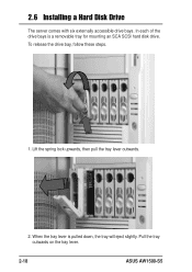
Lift the spring lock upwards, then pull the tray lever outwards. 2. To release the drive bay, follow these steps. 1. When the tray lever is a removable tray for mounting an SCA SCSI hard disk drive. Pull the tray outwards on the tray lever. 2-18 ASUS AW1500-S5 2.6 Installing a Hard Disk Drive The server comes with six externally accessible drive bays. In each of the drive bays is pulled down, the tray will eject slightly.
Lift the spring lock upwards, then pull the tray lever outwards. 2. To release the drive bay, follow these steps. 1. When the tray lever is a removable tray for mounting an SCA SCSI hard disk drive. Pull the tray outwards on the tray lever. 2-18 ASUS AW1500-S5 2.6 Installing a Hard Disk Drive The server comes with six externally accessible drive bays. In each of the drive bays is pulled down, the tray will eject slightly.

AW1500-I5 English Manual
Page 40
To lock, make sure that all expansion cards are properly inserted in place. 2-20 ASUS AW1500-S5 To open, push the lever to the left using your thumb to fasten the expansion cards in the slots, then pull the spring lock lever to release the spring lock. 2. To add or remove expansion cards, follow these steps: 1. 2.7 Screwless Expansion Card Slot The AW1500-S5 chassis is designed with a screwless expansion card slot for Personal Computer Interface (PCI) card installation convenience.
To lock, make sure that all expansion cards are properly inserted in place. 2-20 ASUS AW1500-S5 To open, push the lever to the left using your thumb to fasten the expansion cards in the slots, then pull the spring lock lever to release the spring lock. 2. To add or remove expansion cards, follow these steps: 1. 2.7 Screwless Expansion Card Slot The AW1500-S5 chassis is designed with a screwless expansion card slot for Personal Computer Interface (PCI) card installation convenience.


