

AW1500-I5 English Manual
Page 12
...10) AC power cord (1 piece) 11) Support CD that include drivers, utilities and the PC-cillin anti-virus software 12) ASUS PCI-SCU3 Ultra160 SCSI controller support CD 13) Motherboard user guide 14) System user guide 15) LSI SCSI controller user guide 16) Chassis roller wheels (4 sets) 17... HDD bridge board (5 pieces) 2) ASUS AS-35 5U rackmount rail kit 3) ASUS PXL-S30 U320 LSI 1030 SCSI Card 4) ASUS PXI-G45 Gb LAN card 5) ASUS AGP8X V9280 graphics card If any of the above items is missing, contact your dealer. I-4 ASUS AW1500-I5 System Package Contents The following checklist enumerates...
...10) AC power cord (1 piece) 11) Support CD that include drivers, utilities and the PC-cillin anti-virus software 12) ASUS PCI-SCU3 Ultra160 SCSI controller support CD 13) Motherboard user guide 14) System user guide 15) LSI SCSI controller user guide 16) Chassis roller wheels (4 sets) 17... HDD bridge board (5 pieces) 2) ASUS AS-35 5U rackmount rail kit 3) ASUS PXL-S30 U320 LSI 1030 SCSI Card 4) ASUS PXI-G45 Gb LAN card 5) ASUS AGP8X V9280 graphics card If any of the above items is missing, contact your dealer. I-4 ASUS AW1500-I5 System Package Contents The following checklist enumerates...

AW1500-I5 English Manual
Page 14
...; processor in a 604-pin socket, and includes the latest I/O, LAN, and video technologies through the chipsets embedded on the motherboard. 1.1 System Features The ASUS AW1500-I5 workstation is a stylish server system featuring the ASUS PP-DLW motherboard. Motherboard ASUS PP-DLW Chipset North Bridge: Intel® E7505 North Bridge (Placer) South Bridge: Intel® 82801DA South Bridge (ICH4...
...; processor in a 604-pin socket, and includes the latest I/O, LAN, and video technologies through the chipsets embedded on the motherboard. 1.1 System Features The ASUS AW1500-I5 workstation is a stylish server system featuring the ASUS PP-DLW motherboard. Motherboard ASUS PP-DLW Chipset North Bridge: Intel® E7505 North Bridge (Placer) South Bridge: Intel® 82801DA South Bridge (ICH4...

AW1500-I5 English Manual
Page 24
... you physical injury and damage motherboard components. Placement direction When installing the motherboard, make sure that measures 12 inches x 10.5 inches (30.5 x 26.67 cm). The edge with external ports goes to do so may damage the motherboard. 2-4 ASUS AW1500-I5 Make sure to the chassis....Do not overtighten the screws! The PP-DLW uses the extended ATX form factor that you place it . 2.2 Motherboard placement Before you install the motherboard, study the configuration of your chassis...
... you physical injury and damage motherboard components. Placement direction When installing the motherboard, make sure that measures 12 inches x 10.5 inches (30.5 x 26.67 cm). The edge with external ports goes to do so may damage the motherboard. 2-4 ASUS AW1500-I5 Make sure to the chassis....Do not overtighten the screws! The PP-DLW uses the extended ATX form factor that you place it . 2.2 Motherboard placement Before you install the motherboard, study the configuration of your chassis...

AW1500-I5 English Manual
Page 26
... lever to secure the CPU. Locate the 604-pin ZIF sockets on the side tab to indicate that the socket lever is locked. 2-6 ASUS AW1500-I5 The lever clicks on the motherboard. Unlock the socket by pressing the lever sideways, then lift it is lifted up to at least 115° angle, otherwise the...
... lever to secure the CPU. Locate the 604-pin ZIF sockets on the side tab to indicate that the socket lever is locked. 2-6 ASUS AW1500-I5 The lever clicks on the motherboard. Unlock the socket by pressing the lever sideways, then lift it is lifted up to at least 115° angle, otherwise the...

AW1500-I5 English Manual
Page 28
... connector on the motherboard labeled CPUFAN1. Use CPUFAN2 connector for CPU socket 2. When the heatsink and fan assembly is in place and the fan power cable are connected properly. If you fail to install two CPUs, repeat the same steps for the second CPU heatsink and fan assembly cable. 2-8 ASUS AW1500-I5 The fan...
... connector on the motherboard labeled CPUFAN1. Use CPUFAN2 connector for CPU socket 2. When the heatsink and fan assembly is in place and the fan power cable are connected properly. If you fail to install two CPUs, repeat the same steps for the second CPU heatsink and fan assembly cable. 2-8 ASUS AW1500-I5 The fan...
AW1500-I5 English Manual
Page 30
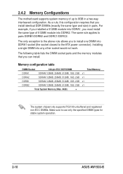
... you can install. 2.4.2 Memory Configurations The motherboard supports system memory of 512MB module into DDRA2. The same rule applies to 8GB in pairs. Installing a single DIMM into DDRA1 socket (the socket closest to use only the specified DIMM types for stable system operation. 2-10 ASUS AW1500-I5 Memory configuration table DIMM Socket 184-pin...
... you can install. 2.4.2 Memory Configurations The motherboard supports system memory of 512MB module into DDRA2. The same rule applies to 8GB in pairs. Installing a single DIMM into DDRA1 socket (the socket closest to use only the specified DIMM types for stable system operation. 2-10 ASUS AW1500-I5 Memory configuration table DIMM Socket 184-pin...
AW1500-I5 English Manual
Page 44
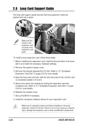
... cards are positioned firmly in the expansion card guide. Refer to do so may cause you physical injury, damage the expansion card or other motherboard components. 2-24 ASUS AW1500-I5 Make sure to the chassis by locking the expansion card slot screwless lock. Remove the system chassis cover. 3. Secure the card to unplug the...
... cards are positioned firmly in the expansion card guide. Refer to do so may cause you physical injury, damage the expansion card or other motherboard components. 2-24 ASUS AW1500-I5 Make sure to the chassis by locking the expansion card slot screwless lock. Remove the system chassis cover. 3. Secure the card to unplug the...

AW1500-I5 English Manual
Page 46
2.10 Chassis Fan The chassis is cooled by squeezing the pin tail and pushing the pin to the rear panel. 3. Release all four (4) pin-locks by a 12-cm chassis fan mounted at the rear panel.The chassis fan status can be monitored remotely through the ASUS® Server Management Software (ASMS). 2.10.1 Removing the 12-cm chassis fan To remove the 12-cm chassis fan, follow these steps. 1. Pull out the 12-cm chassis fan. 2-26 ASUS AW1500-I5 chassis fan pin-locks 2. Remove the 12-cm chassis fan 3-pin power cable (SYSFAN3) from the motherboard.
2.10 Chassis Fan The chassis is cooled by squeezing the pin tail and pushing the pin to the rear panel. 3. Release all four (4) pin-locks by a 12-cm chassis fan mounted at the rear panel.The chassis fan status can be monitored remotely through the ASUS® Server Management Software (ASMS). 2.10.1 Removing the 12-cm chassis fan To remove the 12-cm chassis fan, follow these steps. 1. Pull out the 12-cm chassis fan. 2-26 ASUS AW1500-I5 chassis fan pin-locks 2. Remove the 12-cm chassis fan 3-pin power cable (SYSFAN3) from the motherboard.

AW1500-I5 English Manual
Page 56
reserved A-6 5. Power case top view 1 23 4 5 6 7 8 9 1. 24-pin to motherboard ATX connector 2. 12V 8-pin to motherboard connector 3. DVD-ROM 7. reserved 6. SCSI Backplane 9. reserved ASUS AW1500-I5 Floppy disk drive 4. SCSI Backplane 8.
reserved A-6 5. Power case top view 1 23 4 5 6 7 8 9 1. 24-pin to motherboard ATX connector 2. 12V 8-pin to motherboard connector 3. DVD-ROM 7. reserved 6. SCSI Backplane 9. reserved ASUS AW1500-I5 Floppy disk drive 4. SCSI Backplane 8.

