AT5IONT-I User's manual
Page 3
Contents Notices...v Safety information vi About this guide vi AT5IONT-I Series specifications summary viii Chapter 1: Product introduction 1.1 Before you proceed 1-1 1.2 Motherboard overview 1-2 1.2.1 Motherboard layout 1-2 1.2.2 Layout contents 1-3 1.3 Central Processing ...Rear panel connectors 1-8 1.7.2 Internal connectors 1-10 1.8 Software support 1-14 1.8.1 Installing an operating system 1-14 1.8.2 Support DVD information 1-14 1.8.3 ASUS VideoSecurity 1-15 1.8.4 ASUS Home Theater Gate 1-17 1.8.5 ASUS @Vibe 1-20 Chapter 2: BIOS information 2.1 Managing and updating your BIOS...
Contents Notices...v Safety information vi About this guide vi AT5IONT-I Series specifications summary viii Chapter 1: Product introduction 1.1 Before you proceed 1-1 1.2 Motherboard overview 1-2 1.2.1 Motherboard layout 1-2 1.2.2 Layout contents 1-3 1.3 Central Processing ...Rear panel connectors 1-8 1.7.2 Internal connectors 1-10 1.8 Software support 1-14 1.8.1 Installing an operating system 1-14 1.8.2 Support DVD information 1-14 1.8.3 ASUS VideoSecurity 1-15 1.8.4 ASUS Home Theater Gate 1-17 1.8.5 ASUS @Vibe 1-20 Chapter 2: BIOS information 2.1 Managing and updating your BIOS...
AT5IONT-I User's manual
Page 10
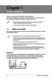
...supply. Chapter 1 Product introduction Thank you install or remove any component, ensure that lights up to page ix for buying an ASUS® AT5IONT-I Series motherboard! This is detached from the wall socket before removing or plugging in soft-off or the power cord is .... • Before you for the list of the onboard LED. The illustration below shows the location of accessories. • AT5IONT-I Series motherboards include AT5IONT-I and AT5IONT-I DELUXE Onboard LED 1-1 Chapter 1: Product introduction Failure to do so may cause severe damage to avoid touching the ICs on...
...supply. Chapter 1 Product introduction Thank you install or remove any component, ensure that lights up to page ix for buying an ASUS® AT5IONT-I Series motherboard! This is detached from the wall socket before removing or plugging in soft-off or the power cord is .... • Before you for the list of the onboard LED. The illustration below shows the location of accessories. • AT5IONT-I Series motherboards include AT5IONT-I and AT5IONT-I DELUXE Onboard LED 1-1 Chapter 1: Product introduction Failure to do so may cause severe damage to avoid touching the ICs on...
AT5IONT-I User's manual
Page 11
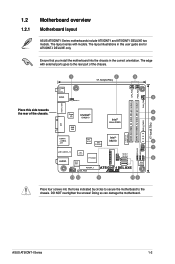
...USBPW56 LAN1_USB3.0_12 NEC USB3.0 AUDIO ALC 887 P17C9X20 USB56 SATA1 SATA2 CLRTC 8 8Mb BIOS AAFP PCIEX4_1 SB_PWR AT5IONT-I DELUXE only. ASUS AT5IONT-I DELUXE two models. DO NOT overtighten the screws! Ensure that you install the motherboard into the holes ... into the chassis in this side towards the rear of the chassis. 1.2 1.2.1 Motherboard overview Motherboard layout ASUS AT5IONT-I Series motherboards include AT5IONT-I and AT5IONT-I Series 1-2 The layout illustrations in the correct orientation. The edge with models. The layout varies with external...
...USBPW56 LAN1_USB3.0_12 NEC USB3.0 AUDIO ALC 887 P17C9X20 USB56 SATA1 SATA2 CLRTC 8 8Mb BIOS AAFP PCIEX4_1 SB_PWR AT5IONT-I DELUXE only. ASUS AT5IONT-I DELUXE two models. DO NOT overtighten the screws! Ensure that you install the motherboard into the holes ... into the chassis in this side towards the rear of the chassis. 1.2 1.2.1 Motherboard overview Motherboard layout ASUS AT5IONT-I Series motherboards include AT5IONT-I and AT5IONT-I Series 1-2 The layout illustrations in the correct orientation. The edge with models. The layout varies with external...
AT5IONT-I User's manual
Page 13
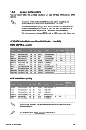
...HYNIX KTC ELPIDA ELPIDA Chip NO. J1108BDBG-DJ-F 9 1.5V J1108BDBG-DJ-F - - ASUS AT5IONT-I Series Motherboard Qualified Vendors Lists (QVL) DDR3-1067 MHz capability Vendors Part No. AT5IONT-I Series 1-4 Timing Voltage AM5D5808AEWSBG 9 - 1.4.2 Memory configurations You may install 512MB, 1GB,...• • • • • • • • DDR3 1333MHz and DDR3 1067MHz memory modules run at www.asus.com for the OS can be about 3GB or less. H5TQ1G83TFR - - Size APACER AS01GFA06C7NBGC 1GB HYNIX HMT112S6BFR6C-G7 1GB KINGSTON KVR1066D3S7/1G 1GB ...
...HYNIX KTC ELPIDA ELPIDA Chip NO. J1108BDBG-DJ-F 9 1.5V J1108BDBG-DJ-F - - ASUS AT5IONT-I Series Motherboard Qualified Vendors Lists (QVL) DDR3-1067 MHz capability Vendors Part No. AT5IONT-I Series 1-4 Timing Voltage AM5D5808AEWSBG 9 - 1.4.2 Memory configurations You may install 512MB, 1GB,...• • • • • • • • DDR3 1333MHz and DDR3 1067MHz memory modules run at www.asus.com for the OS can be about 3GB or less. H5TQ1G83TFR - - Size APACER AS01GFA06C7NBGC 1GB HYNIX HMT112S6BFR6C-G7 1GB KINGSTON KVR1066D3S7/1G 1GB ...
AT5IONT-I User's manual
Page 15
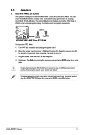
... the boot process and enter BIOS setup to pins 2-3. Removing the cap will cause system boot failure! ASUS AT5IONT-I DELUXE Clear RTC RAM To erase the RTC RAM: 1. CLRTC 12 23 AT5IONT-I DELUXE Normal (Default) Clear RTC AT5IONT-I Series 1-6 Except when clearing the RTC RAM, never remove the cap on pins 2-3 for about 5-10...
... the boot process and enter BIOS setup to pins 2-3. Removing the cap will cause system boot failure! ASUS AT5IONT-I DELUXE Clear RTC RAM To erase the RTC RAM: 1. CLRTC 12 23 AT5IONT-I DELUXE Normal (Default) Clear RTC AT5IONT-I Series 1-6 Except when clearing the RTC RAM, never remove the cap on pins 2-3 for about 5-10...
AT5IONT-I User's manual
Page 17
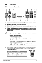
... BLINKING Data activity SPEED LED Status OFF ORANGE GREEN Description 10 Mbps connection 100 Mbps connection 1 Gbps connection ACT/LINK SPEED LED LED LAN port ASUS AT5IONT-I DELUXE only). This port connects to a Local Area Network (LAN) through a network hub. Working distance up to the table below : 1. Switch on.... • Under Windows® XP, if the Bluetooth Driver item is for the LAN port LED indications. Open the Support DVD and click ASUS InstAll. 5. LAN (RJ-45) port. This port is not displayed on the PSU and boot up your computer and switch off the Power ...
... BLINKING Data activity SPEED LED Status OFF ORANGE GREEN Description 10 Mbps connection 100 Mbps connection 1 Gbps connection ACT/LINK SPEED LED LED LAN port ASUS AT5IONT-I DELUXE only). This port connects to a Local Area Network (LAN) through a network hub. Working distance up to the table below : 1. Switch on.... • Under Windows® XP, if the Bluetooth Driver item is for the LAN port LED indications. Open the Support DVD and click ASUS InstAll. 5. LAN (RJ-45) port. This port is not displayed on the PSU and boot up your computer and switch off the Power ...
AT5IONT-I User's manual
Page 19
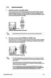
.... The plug from the power supply is designed to the Recommended Power Supply Wattage Calculator at http://support.asus. GND RSATA_TXP2 RSATA_TXN2 GND RSATA_RXP2 RSATA_RXN2 GND AT5IONT-I AT5IONT-I only) This connector is faster than the standard parallel ATA (133 MB/s). The Serial ATA 3Gb/s is... for Serial ATA 3Gb/s hard disk drives and optical disk drives. SATA1 SATA2 AT5IONT-I DELUXE AT5IONT-I Series 1-10 Find the proper orientation and push down firmly until the connector completely fits. ASUS AT5IONT-I DELUXE SATA connectors • Install the Windows® XP Service Pack 2 ...
.... The plug from the power supply is designed to the Recommended Power Supply Wattage Calculator at http://support.asus. GND RSATA_TXP2 RSATA_TXN2 GND RSATA_RXP2 RSATA_RXN2 GND AT5IONT-I AT5IONT-I only) This connector is faster than the standard parallel ATA (133 MB/s). The Serial ATA 3Gb/s is... for Serial ATA 3Gb/s hard disk drives and optical disk drives. SATA1 SATA2 AT5IONT-I DELUXE AT5IONT-I Series 1-10 Find the proper orientation and push down firmly until the connector completely fits. ASUS AT5IONT-I DELUXE SATA connectors • Install the Windows® XP Service Pack 2 ...
AT5IONT-I User's manual
Page 21
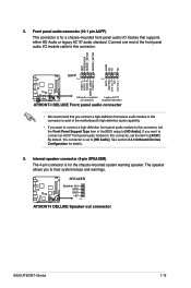
... See section 2.4.4 Onboard Devices Configuration for a chassis-mounted front panel audio I Series 1-12 SPEAKER AT5IONT-I DELUXE Speaker Out GND GND +5V PIN 1 AT5IONT-I DELUXE Speaker out connector ASUS AT5IONT-I /O module that you connect a high-definition front panel audio module to this connector to avail ... PIN 1 MIC2 MICPWR Line out_R NC Line out_L PORT1 L PORT1 R PORT2 R SENSE_SEND PORT2 L AT5IONT-I DELUXE HD-audio-compliant Legacy AC'97 pin definition compliant definition AT5IONT-I /O module cable to hear system beeps and warnings. If you to this connector is for the ...
... See section 2.4.4 Onboard Devices Configuration for a chassis-mounted front panel audio I Series 1-12 SPEAKER AT5IONT-I DELUXE Speaker Out GND GND +5V PIN 1 AT5IONT-I DELUXE Speaker out connector ASUS AT5IONT-I /O module that you connect a high-definition front panel audio module to this connector to avail ... PIN 1 MIC2 MICPWR Line out_R NC Line out_L PORT1 L PORT1 R PORT2 R SENSE_SEND PORT2 L AT5IONT-I DELUXE HD-audio-compliant Legacy AC'97 pin definition compliant definition AT5IONT-I /O module cable to hear system beeps and warnings. If you to this connector is for the ...
AT5IONT-I User's manual
Page 23
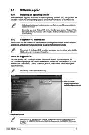
Double-click the ASSETUP.EXE to display their respective menus. ASUS AT5IONT-I Series 1-14 1.8 Software support 1.8.1 Installing an operating system This motherboard supports Windows® XP/Vista/7 Operating Systems (OS). Click Drivers, Utilities, Make Disk, Manual, ... DVD that comes with the motherboard package contains the drivers, software applications, and utilities that you can install to the optical drive. Visit the ASUS website at any time without notice. Always install the latest OS version and corresponding updates to locate the file ASSETUP.EXE from the BIN folder...
Double-click the ASSETUP.EXE to display their respective menus. ASUS AT5IONT-I Series 1-14 1.8 Software support 1.8.1 Installing an operating system This motherboard supports Windows® XP/Vista/7 Operating Systems (OS). Click Drivers, Utilities, Make Disk, Manual, ... DVD that comes with the motherboard package contains the drivers, software applications, and utilities that you can install to the optical drive. Visit the ASUS website at any time without notice. Always install the latest OS version and corresponding updates to locate the file ASSETUP.EXE from the BIN folder...
AT5IONT-I User's manual
Page 25
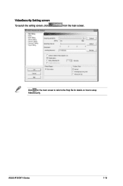
VideoSecurity Setting screen To launch the setting screen, click from the main screen. Click for the main screen to refer to the Help file for details on how to setup VideoSecurity. ASUS AT5IONT-I Series 1-16
VideoSecurity Setting screen To launch the setting screen, click from the main screen. Click for the main screen to refer to the Help file for details on how to setup VideoSecurity. ASUS AT5IONT-I Series 1-16
AT5IONT-I User's manual
Page 27
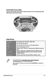
ASUS AT5IONT-I Series 1-18 Internet Radio channel setting Long press the channel number and the station information on the currently playing station will be saved to recognize ..., PowerDVD 8 (Cyberlink), WinDVD 9 (Corel/ InterVideo), KMPlayer, Media Player Classic, RealPlayer and Arcsoft TotalMedia Theatre 3 Windows® Media Player, Winamp, KMPlayer, RealPlayer, iTunes • Visit the ASUS website at http://support.asus.com/download/download.
ASUS AT5IONT-I Series 1-18 Internet Radio channel setting Long press the channel number and the station information on the currently playing station will be saved to recognize ..., PowerDVD 8 (Cyberlink), WinDVD 9 (Corel/ InterVideo), KMPlayer, Media Player Classic, RealPlayer and Arcsoft TotalMedia Theatre 3 Windows® Media Player, Winamp, KMPlayer, RealPlayer, iTunes • Visit the ASUS website at http://support.asus.com/download/download.

AT5IONT-I User's manual
Page 29
To launch ASUS @Vibe ,click Start > All Programs > ASUS > ASUS VIBE > ASUS VIBE. ASUS AT5IONT-I Series 1-20 Launching ASUS @Vibe 1. 1.8.5 ASUS @Vibe ASUS @Vibe allows you to enjoy online entertainment contents including Radio, Live TV and Games, etc. • The ASUS @Vibe service contents differ for each territory. • This utility does not work on Windows® 64-bit XP OS. Install ASUS @Vibe from the motherboard support DVD. 2.
To launch ASUS @Vibe ,click Start > All Programs > ASUS > ASUS VIBE > ASUS VIBE. ASUS AT5IONT-I Series 1-20 Launching ASUS @Vibe 1. 1.8.5 ASUS @Vibe ASUS @Vibe allows you to enjoy online entertainment contents including Radio, Live TV and Games, etc. • The ASUS @Vibe service contents differ for each territory. • This utility does not work on Windows® 64-bit XP OS. Install ASUS @Vibe from the motherboard support DVD. 2.
AT5IONT-I User's manual
Page 30
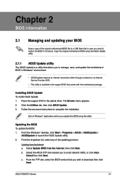
...(ISP). • This utility is a utility that allows you to avoid network traffic, or click Auto Select then click Next. Select the ASUS FTP site nearest you to manage, save, and update the motherboard BIOS in the support DVD that comes with the motherboard package. The Drivers ...174; applications before you need to download then click Next. Select Update BIOS from the Internet a. b. c. Click the Utilities tab, then click ASUS Update. 3. ASUS AT5IONT-I Series 2-1 From the FTP site, select the BIOS version that you wish to restore the BIOS in the optical drive.
...(ISP). • This utility is a utility that allows you to avoid network traffic, or click Auto Select then click Next. Select the ASUS FTP site nearest you to manage, save, and update the motherboard BIOS in the support DVD that comes with the motherboard package. The Drivers ...174; applications before you need to download then click Next. Select Update BIOS from the Internet a. b. c. Click the Utilities tab, then click ASUS Update. 3. ASUS AT5IONT-I Series 2-1 From the FTP site, select the BIOS version that you wish to restore the BIOS in the optical drive.
AT5IONT-I User's manual
Page 32
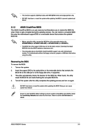
... the BIOS file in the removable device into AT5IONT.ROM (for AT5IONT-I Series 2-3 Recovering the BIOS To recover the BIOS: 1. Turn on again. Download the latest BIOS file from the ASUS website at www.asus.com. • The removable device that ASUS CrashFree BIOS support vary with FAT 32/16 ...format and single partition only. • DO NOT shut down or reset the system while updating the BIOS! ASUS AT5IONT-I DELUXE) or AT5IONTI.ROM (for the BIOS file. For motherboards without the floppy connector, prepare a USB flash disk before using this utility....
... the BIOS file in the removable device into AT5IONT.ROM (for AT5IONT-I Series 2-3 Recovering the BIOS To recover the BIOS: 1. Turn on again. Download the latest BIOS file from the ASUS website at www.asus.com. • The removable device that ASUS CrashFree BIOS support vary with FAT 32/16 ...format and single partition only. • DO NOT shut down or reset the system while updating the BIOS! ASUS AT5IONT-I DELUXE) or AT5IONTI.ROM (for the BIOS file. For motherboards without the floppy connector, prepare a USB flash disk before using this utility....

AT5IONT-I User's manual
Page 34
... entering Setup, the BIOS automatically detects the presence of SATA drive. Configuration options: [Auto] [0] [1] [2] [3] [4] DMA Mode [Auto] Selects the DMA mode. Configuration options: [Disabled] [Enabled] ASUS AT5IONT-I Series 2-5 The BIOS automatically detects the values opposite the dimmed items (Device, Vendor, Size, LBA Mode, Block Mode, PIO Mode, Async DMA, Ultra DMA, and...
... entering Setup, the BIOS automatically detects the presence of SATA drive. Configuration options: [Auto] [0] [1] [2] [3] [4] DMA Mode [Auto] Selects the DMA mode. Configuration options: [Disabled] [Enabled] ASUS AT5IONT-I Series 2-5 The BIOS automatically detects the values opposite the dimmed items (Device, Vendor, Size, LBA Mode, Block Mode, PIO Mode, Async DMA, Ultra DMA, and...
AT5IONT-I User's manual
Page 36
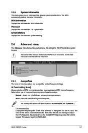
... item to the system bus and PCI bus. allows you set overclocking parameters. The following item appears only when you to adjust the CPU frequency. ASUS AT5IONT-I DELUXE BIOS Setup Power Boot Tools Exit JumperFree CPU Configuration Chipset Onboard Devices Configuration USB Configuration PCIPnP Version 0214 2.4.1 JumperFree The items in this item...
... item to the system bus and PCI bus. allows you set overclocking parameters. The following item appears only when you to adjust the CPU frequency. ASUS AT5IONT-I DELUXE BIOS Setup Power Boot Tools Exit JumperFree CPU Configuration Chipset Onboard Devices Configuration USB Configuration PCIPnP Version 0214 2.4.1 JumperFree The items in this item...
AT5IONT-I User's manual
Page 38
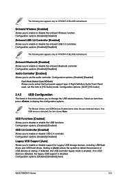
...Select an item then press to detect the presence of USB devices at startup. The following item appears only on AT5IONT-I Series 2-9 Onboard Wireless [Enabled] Allows you to enable or disable USB 2.0 controller. The Module Version and ...: [Enabled] [Disabled] The following item appears only on AT5IONT-I DELUXE motherboard. Configuration options: [Enabled] [Disabled] Audio Controller [Enabled] Allows you to change the USB-related features. Configuration options: [Disabled] [Enabled] [Auto] ASUS AT5IONT-I DELUXE motherboard. Configuration options: [Enabled] [Disabled] Front ...
...Select an item then press to detect the presence of USB devices at startup. The following item appears only on AT5IONT-I Series 2-9 Onboard Wireless [Enabled] Allows you to enable or disable USB 2.0 controller. The Module Version and ...: [Enabled] [Disabled] The following item appears only on AT5IONT-I DELUXE motherboard. Configuration options: [Enabled] [Disabled] Audio Controller [Enabled] Allows you to change the USB-related features. Configuration options: [Disabled] [Enabled] [Auto] ASUS AT5IONT-I DELUXE motherboard. Configuration options: [Enabled] [Disabled] Front ...
AT5IONT-I User's manual
Page 40
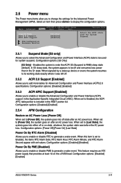
...Power Off] When set to [Power Off], the system goes into either off or on the +5VSB lead. Configuration options: [Disabled] [Enabled] ASUS AT5IONT-I DELUXE BIOS Setup Power Boot Tools Exit Suspend Mode [S3 only] ACPI 2.0 Support [Enabled] ACPI APIC Support [Enabled] APM Configuration Hardware Monitor ...power loss. 2.5 Power menu The Power menu items allow you to be off and consumes less power than in the S1 state. Main Advanced AT5IONT-I Series 2-11 Enables the system to enter the ACPI S3 (Suspend to generate a wake event. Configuration options: [Power Off] [Power On]...
...Power Off] When set to [Power Off], the system goes into either off or on the +5VSB lead. Configuration options: [Disabled] [Enabled] ASUS AT5IONT-I DELUXE BIOS Setup Power Boot Tools Exit Suspend Mode [S3 only] ACPI 2.0 Support [Enabled] ACPI APIC Support [Enabled] APM Configuration Hardware Monitor ...power loss. 2.5 Power menu The Power menu items allow you to be off and consumes less power than in the S1 state. Main Advanced AT5IONT-I Series 2-11 Enables the system to enter the ACPI S3 (Suspend to generate a wake event. Configuration options: [Power Off] [Power On]...

AT5IONT-I User's manual
Page 42
... POST. 2.6.2 Boot Settings Configuration Quick Boot [Enabled] Enabling this item to [Enabled] to set a password, this item shows Installed. ASUS AT5IONT-I Series 2-13 AddOn ROM Display Mode [Force BIOS] Sets the display mode for the NumLock. The Supervisor Password item on state for ... the password when prompted. When set to [Enabled], the system displays the message Press DEL to run Setup during system startup, press when ASUS Logo appears. • To access Windows® OS in a password containing up to change the supervisor password. Configuration options: [Disabled] ...
... POST. 2.6.2 Boot Settings Configuration Quick Boot [Enabled] Enabling this item to [Enabled] to set a password, this item shows Installed. ASUS AT5IONT-I Series 2-13 AddOn ROM Display Mode [Force BIOS] Sets the display mode for the NumLock. The Supervisor Password item on state for ... the password when prompted. When set to [Enabled], the system displays the message Press DEL to run Setup during system startup, press when ASUS Logo appears. • To access Windows® OS in a password containing up to change the supervisor password. Configuration options: [Disabled] ...
AT5IONT-I User's manual
Page 44
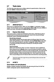
... Express Gate's settings as well as any personal information stored by the web browser (bookmarks, cookies, browsing history, etc.). Main Advanced AT5IONT-I Series 2-15 This is a unique instant-on environment that provides quick access to the BIOS so that the system waits at the first... countdown duration that the user data will run the utility to display the sub-menu. Configuration options: [Disabled] [Enabled] ASUS AT5IONT-I DELUXE BIOS Setup Power Boot Tools Exit ASUS EZ Flash 2 Express Gate Enter OS Timer Reset User Data AI NET2 [Auto] [10 Seconds] [No] Version 0214 ...
... Express Gate's settings as well as any personal information stored by the web browser (bookmarks, cookies, browsing history, etc.). Main Advanced AT5IONT-I Series 2-15 This is a unique instant-on environment that provides quick access to the BIOS so that the system waits at the first... countdown duration that the user data will run the utility to display the sub-menu. Configuration options: [Disabled] [Enabled] ASUS AT5IONT-I DELUXE BIOS Setup Power Boot Tools Exit ASUS EZ Flash 2 Express Gate Enter OS Timer Reset User Data AI NET2 [Auto] [10 Seconds] [No] Version 0214 ...


