User Manual
Page 1
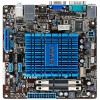
Motherboard AT4NM10T-I
Motherboard AT4NM10T-I
User Manual
Page 3
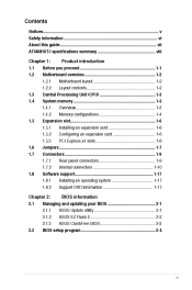
Contents Notices...v Safety information...vi About this guide...vii AT4NM10T-I specifications summary...viii Chapter 1: 1.1 1.2 Before you proceed...1-1 Motherboard overview...1-2 1.2.1 1.2.2 Motherboard layout...1-2 Layout contents...1-2 Product introduction 1.3 1.4 Central Processing Unit (CPU)...1-3 System memory...1-3 1.4.1 1.4.2 ... information...1-17 1.8 Software support...1-17 Chapter 2: 2.1 Managing and updating your BIOS...2-1 2.1.1 2.1.2 2.1.3 ASUS Update utility...2-1 ASUS EZ Flash 2...2-2 ASUS CrashFree BIOS...2-3 BIOS information 2.2 BIOS setup program...2-4 iii
Contents Notices...v Safety information...vi About this guide...vii AT4NM10T-I specifications summary...viii Chapter 1: 1.1 1.2 Before you proceed...1-1 Motherboard overview...1-2 1.2.1 1.2.2 Motherboard layout...1-2 Layout contents...1-2 Product introduction 1.3 1.4 Central Processing Unit (CPU)...1-3 System memory...1-3 1.4.1 1.4.2 ... information...1-17 1.8 Software support...1-17 Chapter 2: 2.1 Managing and updating your BIOS...2-1 2.1.1 2.1.2 2.1.3 ASUS Update utility...2-1 ASUS EZ Flash 2...2-2 ASUS CrashFree BIOS...2-3 BIOS information 2.2 BIOS setup program...2-4 iii
User Manual
Page 6
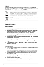
..., humidity, and temperature extremes. vi DO NOT throw the mercury-containing button cell battery in our products at ASUS REACH website at http://csr.asus.com/english/REACH.htm. Operation safety Before installing the motherboard and adding devices on a stable surface. Before using an adapter or extension cord. Place the product on it...
..., humidity, and temperature extremes. vi DO NOT throw the mercury-containing button cell battery in our products at ASUS REACH website at http://csr.asus.com/english/REACH.htm. Operation safety Before installing the motherboard and adding devices on a stable surface. Before using an adapter or extension cord. Place the product on it...
User Manual
Page 7
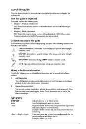
... guide To ensure that you must press the enclosed key. DANGER/WARNING: Information to prevent injury to yourself when trying to the ASUS contact information. Where to complete a task. Example: means that you complete a task. Refer to complete a task. CAUTION: ...8226; Chapter 1: Product introduction • This chapter describes the features of the BIOS parameters are also provided. Detailed descriptions of the motherboard and the new technology it supports. These documents are linked with a plus sign (+). If you MUST follow to find more keys ...
... guide To ensure that you must press the enclosed key. DANGER/WARNING: Information to prevent injury to yourself when trying to the ASUS contact information. Where to complete a task. Example: means that you complete a task. Refer to complete a task. CAUTION: ...8226; Chapter 1: Product introduction • This chapter describes the features of the BIOS parameters are also provided. Detailed descriptions of the motherboard and the new technology it supports. These documents are linked with a plus sign (+). If you MUST follow to find more keys ...

User Manual
Page 11
...do so may cause severe damage to page ix for buying an ASUS® AT4NM10T-I Onboard LED 1-1 Chapter 1: Product introduction If any of the items is damaged or missing, contact your motherboard package. The illustration below shows the location of the onboard LED. ... 1 Product introduction Thank you for the list of accessories. Refer to the motherboard, peripherals, or components. SB_PWR AT4NM10T-I ON Standby Power OFF Powered Off AT4NM10T-I motherboard! Before you start installing the motherboard, and hardware devices on it on them. • Whenever you uninstall any...
...do so may cause severe damage to page ix for buying an ASUS® AT4NM10T-I Onboard LED 1-1 Chapter 1: Product introduction If any of the items is damaged or missing, contact your motherboard package. The illustration below shows the location of the onboard LED. ... 1 Product introduction Thank you for the list of accessories. Refer to the motherboard, peripherals, or components. SB_PWR AT4NM10T-I ON Standby Power OFF Powered Off AT4NM10T-I motherboard! Before you start installing the motherboard, and hardware devices on it on them. • Whenever you uninstall any...
User Manual
Page 12
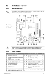
...) Internal speaker connector (4-pin SPEAKER) Digital audio connector (4-1 pin SPDIF_OUT) 1-15 1-8 Front panel audio connector (10-1 pin AAFP) 1-13 ASUS AT4NM10T-I 17.0cm(6.7in) LAN1_USB12 RTL 8111E Intel® NM10 SB_PWR 2 8 9 8Mb BIOS AUDIO AAFP VIA VT1705 Lithium Cell CMOS Power JMB ...14 13 12 11 10 Place four screws into the chassis in the correct orientation. 1.2 1.2.1 Motherboard overview Motherboard layout Ensure that you install the motherboard into the holes indicated by circles to secure the motherboard to the rear part of the chassis. 1 2 3 17.0cm(6.7in) 4 5 6...
...) Internal speaker connector (4-pin SPEAKER) Digital audio connector (4-1 pin SPDIF_OUT) 1-15 1-8 Front panel audio connector (10-1 pin AAFP) 1-13 ASUS AT4NM10T-I 17.0cm(6.7in) LAN1_USB12 RTL 8111E Intel® NM10 SB_PWR 2 8 9 8Mb BIOS AUDIO AAFP VIA VT1705 Lithium Cell CMOS Power JMB ...14 13 12 11 10 Place four screws into the chassis in the correct orientation. 1.2 1.2.1 Motherboard overview Motherboard layout Ensure that you install the motherboard into the holes indicated by circles to secure the motherboard to the rear part of the chassis. 1 2 3 17.0cm(6.7in) 4 5 6...
User Manual
Page 13
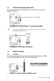
... connect the CPU fan cable to the connector on the motherboard labeled CPU_FAN. CPU_FAN GND CPU FAN PWR CPU FAN IN CPU FAN PWM DIMM_A1 DIMM_A2 AT4NM10T-I CPU fan connector 1.4 1.4.1 System memory Overview The motherboard comes with an onboard Intel® Atom™ D425 ...processor and a specially designed CPU heatsink. Intel® Atom™ processor D425 AT4NM10T-I AT4NM10T-I 204-pin DDR3 SO-DIMM sockets 1-3 ...
... connect the CPU fan cable to the connector on the motherboard labeled CPU_FAN. CPU_FAN GND CPU FAN PWR CPU FAN IN CPU FAN PWM DIMM_A1 DIMM_A2 AT4NM10T-I CPU fan connector 1.4 1.4.1 System memory Overview The motherboard comes with an onboard Intel® Atom™ D425 ...processor and a specially designed CPU heatsink. Intel® Atom™ processor D425 AT4NM10T-I AT4NM10T-I 204-pin DDR3 SO-DIMM sockets 1-3 ...
User Manual
Page 14
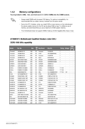
... megabits (Mb) chips or less. DIMM Timing Voltage support A* B* 1.5V 1.5V 1.5V 1.5V 7-7-7-20 7-7-7-20 7-7-7-20 7 7 7 - ASUS AT4NM10T-I Motherboard Qualified Vendors Lists (QVL) DDR3-1066 MHz capability Vendor Transcend Transcend Transcend Transcend APACER APACER CORSAIR CORSAIR G.SKILL G.SKILL GEIL HYNIX KINGMAX KINGMAX KINGMAX KINGSTON... Elixir KINGTIGER KINGTIGER KINGTIGER Part No. For optimum compatibility, it is recommended that you install 4GB or more memory on the motherboard, the actual usable memory for the OS can be about 3GB or less. 1.4.2 You may install 512MB, 1GB, and ...
... megabits (Mb) chips or less. DIMM Timing Voltage support A* B* 1.5V 1.5V 1.5V 1.5V 7-7-7-20 7-7-7-20 7-7-7-20 7 7 7 - ASUS AT4NM10T-I Motherboard Qualified Vendors Lists (QVL) DDR3-1066 MHz capability Vendor Transcend Transcend Transcend Transcend APACER APACER CORSAIR CORSAIR G.SKILL G.SKILL GEIL HYNIX KINGMAX KINGMAX KINGMAX KINGSTON... Elixir KINGTIGER KINGTIGER KINGTIGER Part No. For optimum compatibility, it is recommended that you install 4GB or more memory on the motherboard, the actual usable memory for the OS can be about 3GB or less. 1.4.2 You may install 512MB, 1GB, and ...

User Manual
Page 15
... at 800 MHz on the next page) 1-5 Chapter 1: Product introduction The 1333/1066 MHz memory modules run at www.asus.com for the latest QVL. (continued on this motherboard. DS DS DS DS DS DS DS DS DS DS DS DS DS DS DS DS DS DS DS DS DS DS DS...
... at 800 MHz on the next page) 1-5 Chapter 1: Product introduction The 1333/1066 MHz memory modules run at www.asus.com for the latest QVL. (continued on this motherboard. DS DS DS DS DS DS DS DS DS DS DS DS DS DS DS DS DS DS DS DS DS DS DS...
User Manual
Page 16
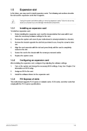
...to the card. See Chapter 2 for the expansion card. 1.5 Expansion slot In the future, you may cause you physical injury and damage motherboard components. 1.5.1 1. 2. 3. 4. 5. 6. Remove the bracket opposite the slot that came with the screw you removed earlier. Replace the ...ASUS AT4NM10T-I 1-6 Unplug the power cord before adding or removing expansion cards. Turn on the slot. Keep the screw for the card. After installing the expansion card, configure it supports. Assign an IRQ to install expansion cards. Remove the system unit cover (if your motherboard...
...to the card. See Chapter 2 for the expansion card. 1.5 Expansion slot In the future, you may cause you physical injury and damage motherboard components. 1.5.1 1. 2. 3. 4. 5. 6. Remove the bracket opposite the slot that came with the screw you removed earlier. Replace the ...ASUS AT4NM10T-I 1-6 Unplug the power cord before adding or removing expansion cards. Turn on the slot. Keep the screw for the card. After installing the expansion card, configure it supports. Assign an IRQ to install expansion cards. Remove the system unit cover (if your motherboard...
User Manual
Page 20
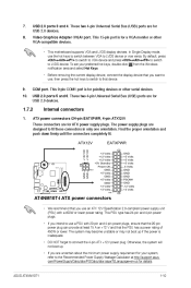
... and press ++ to switch to LVDS device or vice versa. This 9-pin COM1 port is for pointing devices or other VGA-compatible devices. • This motherboard supports VGA and LVDS display devices. This PSU type has 24-pin and 4-pin power plugs. • If you want to use a PSU with a...12 V and that you intend to use , then press the hot keys to switch to fit these connectors in only one orientation. USB 2.0 ports 5 and 6. ASUS AT4NM10T-I AT4NM10T-I ATX power connectors • We recommend that you are designed to that the 20-pin power plug can provide at http://support...
... and press ++ to switch to LVDS device or vice versa. This 9-pin COM1 port is for pointing devices or other VGA-compatible devices. • This motherboard supports VGA and LVDS display devices. This PSU type has 24-pin and 4-pin power plugs. • If you want to use a PSU with a...12 V and that you intend to use , then press the hot keys to switch to fit these connectors in only one orientation. USB 2.0 ports 5 and 6. ASUS AT4NM10T-I AT4NM10T-I ATX power connectors • We recommend that you are designed to that the 20-pin power plug can provide at http://support...
User Manual
Page 21
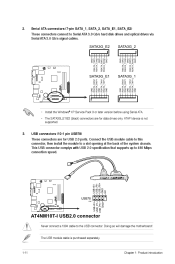
... connectors are for USB 2.0 ports. This USB connector complys with USB 2.0 specification that supports up to the USB connector. USB connectors (10-1 pin USB78) AT4NM10T-I USB78 PIN 1 AT4NM10T-I SATA 3.0Gb/s connectors • Install the Windows® XP Service Pack 3 or later version before using Serial ATA. • The SATA3G_E1/E2 (black) connectors..., then install the module to Serial ATA 3.0 Gb/s hard disk drives and optical drives via Serial ATA 3.0 Gb/s signal cables. Doing so will damage the motherboard!
... connectors are for USB 2.0 ports. This USB connector complys with USB 2.0 specification that supports up to the USB connector. USB connectors (10-1 pin USB78) AT4NM10T-I USB78 PIN 1 AT4NM10T-I SATA 3.0Gb/s connectors • Install the Windows® XP Service Pack 3 or later version before using Serial ATA. • The SATA3G_E1/E2 (black) connectors..., then install the module to Serial ATA 3.0 Gb/s hard disk drives and optical drives via Serial ATA 3.0 Gb/s signal cables. Doing so will damage the motherboard!
User Manual
Page 23
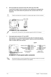
...10-1 pin AAFP) This connector is for a chassis-mounted front panel audio I /O module cable to this connector to avail of the motherboard's high-definition audio capability. 1-13 Chapter 1: Product introduction Connect one end of the connector. 6. CPU and chassis fan connectors (4-pin CPU_FAN...definition Legacy AC'97 compliant definition AT4NM10T-I fan connectors Only 4-pin CPU_FAN and CHA_FAN connectors support the ASUS Q-FAN feature. 7. Both CPU and chassis fan These fan connectors are not jumpers! Do not place jumper caps on the motherboard, ensuring that you connect a ...
...10-1 pin AAFP) This connector is for a chassis-mounted front panel audio I /O module cable to this connector to avail of the motherboard's high-definition audio capability. 1-13 Chapter 1: Product introduction Connect one end of the connector. 6. CPU and chassis fan connectors (4-pin CPU_FAN...definition Legacy AC'97 compliant definition AT4NM10T-I fan connectors Only 4-pin CPU_FAN and CHA_FAN connectors support the ASUS Q-FAN feature. 7. Both CPU and chassis fan These fan connectors are not jumpers! Do not place jumper caps on the motherboard, ensuring that you connect a ...
User Manual
Page 27
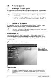
... for reference only. If Autorun is NOT enabled in your computer, browse the contents of ASUS motherboard. Double-click the ASSETUP.EXE to display their respective menus. Visit the ASUS website at any time without notice. Support DVD information To run the DVD. 1-17 Chapter ...1: Product introduction 1.8 1.8.1 Software support Installing an operating system This motherboard supports Windows® XP/Vista/7 Operating Systems (...
... for reference only. If Autorun is NOT enabled in your computer, browse the contents of ASUS motherboard. Double-click the ASSETUP.EXE to display their respective menus. Visit the ASUS website at any time without notice. Support DVD information To run the DVD. 1-17 Chapter ...1: Product introduction 1.8 1.8.1 Software support Installing an operating system This motherboard supports Windows® XP/Vista/7 Operating Systems (...
User Manual
Page 28
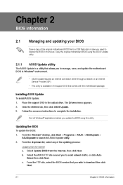
... a. From the dropdown list, select any of the original motherboard BIOS file to a USB flash disk in case you need to manage, save, and update the motherboard BIOS in Windows® environment. • ASUS Update requires an Internet connection either through a network or an... installation. The Drivers menu appears. Updating the BIOS To update the BIOS: 1. 2. b. Copy the original motherboard BIOS using this utility. Click the Utilities tab, then click ASUS Update. Chapter 2 BIOS information 2.1 Managing and updating your BIOS Save a copy of the updating process: Updating...
... a. From the dropdown list, select any of the original motherboard BIOS file to a USB flash disk in case you need to manage, save, and update the motherboard BIOS in Windows® environment. • ASUS Update requires an Internet connection either through a network or an... installation. The Drivers menu appears. Updating the BIOS To update the BIOS: 1. 2. b. Copy the original motherboard BIOS using this utility. Click the Utilities tab, then click ASUS Update. Chapter 2 BIOS information 2.1 Managing and updating your BIOS Save a copy of the updating process: Updating...
User Manual
Page 30
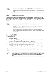
...flash disk before using this utility. Doing so can restore a corrupted BIOS file using the motherboard support DVD or a removable device that allows you to section 2.8 Exit menu for the...BIOS file. • Before using this utility, rename the BIOS file in the removable device into AT4NM10T.ROM. • The BIOS file in the support DVD may not be the latest version. ...settings to the floppy disk drive, if supported. You can cause system boot failure! Turn on again. ASUS CrashFree BIOS Recovering the BIOS To recover the BIOS: 1. 2. 3. 4. Turn off the system after the...
...flash disk before using this utility. Doing so can restore a corrupted BIOS file using the motherboard support DVD or a removable device that allows you to section 2.8 Exit menu for the...BIOS file. • Before using this utility, rename the BIOS file in the removable device into AT4NM10T.ROM. • The BIOS file in the support DVD may not be the latest version. ...settings to the floppy disk drive, if supported. You can cause system boot failure! Turn on again. ASUS CrashFree BIOS Recovering the BIOS To recover the BIOS: 1. 2. 3. 4. Turn off the system after the...

User Manual
Page 31
Press the power button to ensure system compatibility and stability. ASUS AT4NM10T-I 2-4 Entering BIOS Setup at startup To enter BIOS Setup at www.asus.com to download the latest BIOS file for this section are for most conditions to ensure optimum performance. Using the power button, reset button, ... and brief online help to guide you failed to enter BIOS Setup using the BIOS Setup program. Do this option only if you in this motherboard. See section 2.8 Exit Menu. • The BIOS setup screens shown in using the first two options. Press the reset button on your data or...
Press the power button to ensure system compatibility and stability. ASUS AT4NM10T-I 2-4 Entering BIOS Setup at startup To enter BIOS Setup at www.asus.com to download the latest BIOS file for this section are for most conditions to ensure optimum performance. Using the power button, reset button, ... and brief online help to guide you failed to enter BIOS Setup using the BIOS Setup program. Do this option only if you in this motherboard. See section 2.8 Exit Menu. • The BIOS setup screens shown in using the first two options. Press the reset button on your data or...

User Manual
Page 38
...] 2.5.5 Hardware Monitor CPU/MB Temperature [xxxºC/xxxºF] or [Ignored] The onboard hardware monitor automatically detects and displays the CPU/motherboard temperature. If the fan is not connected to turn on the +5VSB lead. Select Ignored if you do not wish to display the ... detects and displays the CPU/chassis fan speeds in rotations per minute (RPM). CPU/Chassis Q-Fan Function [Enabled] Enables or disables the ASUS Q-Fan feature that provides at least 1A on the system. Configuration options: [Disabled] [Enabled] Power On By PS/2 Keyboard [Disabled]...
...] 2.5.5 Hardware Monitor CPU/MB Temperature [xxxºC/xxxºF] or [Ignored] The onboard hardware monitor automatically detects and displays the CPU/motherboard temperature. If the fan is not connected to turn on the +5VSB lead. Select Ignored if you do not wish to display the ... detects and displays the CPU/chassis fan speeds in rotations per minute (RPM). CPU/Chassis Q-Fan Function [Enabled] Enables or disables the ASUS Q-Fan feature that provides at least 1A on the system. Configuration options: [Disabled] [Enabled] Power On By PS/2 Keyboard [Disabled]...
User Manual
Page 44
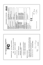
...55013:2001+A1:2003+A2:2006 (510)739-3777/(510)608-4555 conform with part 15 of the FCC Rules. TAIWAN ASUS COMPUTER GmbH HARKORT STR. 21-23, 40880 RATINGEN GERMANY Motherboard AT4NM10T-I, AT5NM10T-I Conforms to begin affixing CE marking:2011 Signature : _____ CE marking (EC conformity marking) Position : CEO Name...including interference that the product 1999/5/EC-R &TTE Directive EN 55024:1998+A1:2001+A2:2003 EN 61000-3-3:2008 EN 55020:2007 Product Name : Motherboard EN 300 328 V1.7.1(2006-05) EN 300 440-1 V1.4.1(2008-05) EN 300 440-2 V1.2.1(2008-03) EN 301 511 V9.0.2(2003-03...
...55013:2001+A1:2003+A2:2006 (510)739-3777/(510)608-4555 conform with part 15 of the FCC Rules. TAIWAN ASUS COMPUTER GmbH HARKORT STR. 21-23, 40880 RATINGEN GERMANY Motherboard AT4NM10T-I, AT5NM10T-I Conforms to begin affixing CE marking:2011 Signature : _____ CE marking (EC conformity marking) Position : CEO Name...including interference that the product 1999/5/EC-R &TTE Directive EN 55024:1998+A1:2001+A2:2003 EN 61000-3-3:2008 EN 55020:2007 Product Name : Motherboard EN 300 328 V1.7.1(2006-05) EN 300 440-1 V1.4.1(2008-05) EN 300 440-2 V1.2.1(2008-03) EN 301 511 V9.0.2(2003-03...


