User Manual
Page 8
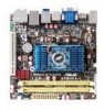
... NVIDIA® GeForce Series DirectX10 graphics processor Supports CUDA technology Supports PhysX technology Supports RGB with max. AT3N7A-I specifications summary CPU Chipset Front Side Bus Memory Graphics Expansion slot Storage Audio LAN USB Fan rated speed ASUS special features Integrated Dual-Core Intel® Atom™ 330 processor NVIDIA® ION™ 533...
... NVIDIA® GeForce Series DirectX10 graphics processor Supports CUDA technology Supports PhysX technology Supports RGB with max. AT3N7A-I specifications summary CPU Chipset Front Side Bus Memory Graphics Expansion slot Storage Audio LAN USB Fan rated speed ASUS special features Integrated Dual-Core Intel® Atom™ 330 processor NVIDIA® ION™ 533...
User Manual
Page 9
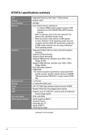
AT3N7A-I specifications summary Rear panel ports Internal connectors BIOS features Accessories Support DVD contents Form Factor 1 x PS/2 Keyboard port 1 x Bluetooth adapter 1 x eSATA port 2 x S/PDIF out ports (Optical & Coaxial) 1 x VGA port 1 x HDMI port 1 x LAN (RJ-45) port 8 x USB 2.0/1.1 ports 8-channel audio I/O ports 1 x USB 2.0/1.1 connector supports additional 2 USB 2.0/1.1 ports 1 x CPU fan connector 1 x Chassis fan...Serial ATA cables 1 x I/O shield 1 x User Manual Drivers ASUS PC Probe II ASUS Update Anti-virus software (OEM version) Mini ITX form factor: 6.75 in x 6.75 in (17.1cm x ...
AT3N7A-I specifications summary Rear panel ports Internal connectors BIOS features Accessories Support DVD contents Form Factor 1 x PS/2 Keyboard port 1 x Bluetooth adapter 1 x eSATA port 2 x S/PDIF out ports (Optical & Coaxial) 1 x VGA port 1 x HDMI port 1 x LAN (RJ-45) port 8 x USB 2.0/1.1 ports 8-channel audio I/O ports 1 x USB 2.0/1.1 connector supports additional 2 USB 2.0/1.1 ports 1 x CPU fan connector 1 x Chassis fan...Serial ATA cables 1 x I/O shield 1 x User Manual Drivers ASUS PC Probe II ASUS Update Anti-virus software (OEM version) Mini ITX form factor: 6.75 in x 6.75 in (17.1cm x ...
User Manual
Page 11
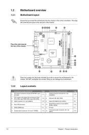
... the screws! System panel connector (10-1 pin F_PANEL) Page 1-11 7. 1.2 1.2.1 Motherboard overview Motherboard layout Ensure that you install the motherboard into the holes indicated by circles to secure the motherboard to the rear part of the chassis. Connectors/Jumpers/Slots/LED Chassis intrusion connector (4-1 ...pin CHASSIS) 1-14 8. PCI slot 1-15 12. The edge with external ports goes to the chassis. USB connector (10-1 pin USB910) 4. CPU, power, and chassis fan connectors...
... the screws! System panel connector (10-1 pin F_PANEL) Page 1-11 7. 1.2 1.2.1 Motherboard overview Motherboard layout Ensure that you install the motherboard into the holes indicated by circles to secure the motherboard to the rear part of the chassis. Connectors/Jumpers/Slots/LED Chassis intrusion connector (4-1 ...pin CHASSIS) 1-14 8. PCI slot 1-15 12. The edge with external ports goes to the chassis. USB connector (10-1 pin USB910) 4. CPU, power, and chassis fan connectors...
User Manual
Page 12
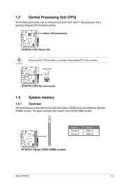
The figure illustrates the location of the DDR2 DIMM sockets: Channel Channel A Channel B Sockets DIMM_A1 DIMM_B1 ASUS AT3N7A-I 1-3 Ensure that the CPU fan cable is connected to the onboard CPU_Fan connector. 1.4 System memory 1.4.1 Overview The motherboard comes with an onboard Dual-Core Intel® Atom™ 330 processor and a specially designed CPU heatsink and fan. 1.3 Central Processing Unit (CPU) The motherboard comes with two Double Data Rate 2 (DDR2) Dual Inline Memory Modules (DIMM) sockets.
The figure illustrates the location of the DDR2 DIMM sockets: Channel Channel A Channel B Sockets DIMM_A1 DIMM_B1 ASUS AT3N7A-I 1-3 Ensure that the CPU fan cable is connected to the onboard CPU_Fan connector. 1.4 System memory 1.4.1 Overview The motherboard comes with an onboard Dual-Core Intel® Atom™ 330 processor and a specially designed CPU heatsink and fan. 1.3 Central Processing Unit (CPU) The motherboard comes with two Double Data Rate 2 (DDR2) Dual Inline Memory Modules (DIMM) sockets.
User Manual
Page 23
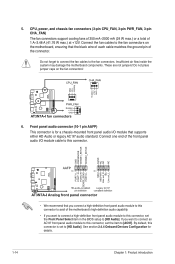
... item in the BIOS setup to the fan connectors on the fan connectors! 6. CPU, power, and chassis fan connectors (3-pin CPU_FAN, 3-pin PWR_FAN, 3-pin CHA_FAN) The fan connectors support cooling fans of 350 mA~2000 mA (24 W max.) or a total of the motherboard's high-definition audio capability. • ...[HD Audio]. 5. Connect one end of the connector. Connect the fan cables to [HD Audio]. By default, this connector to avail of 1 A~3.48 A (41.76 W max.) at +12V. Do not place jumper caps on the motherboard, ensuring that you connect a high-definition front panel audio module to...
... item in the BIOS setup to the fan connectors on the fan connectors! 6. CPU, power, and chassis fan connectors (3-pin CPU_FAN, 3-pin PWR_FAN, 3-pin CHA_FAN) The fan connectors support cooling fans of 350 mA~2000 mA (24 W max.) or a total of the motherboard's high-definition audio capability. • ...[HD Audio]. 5. Connect one end of the connector. Connect the fan cables to [HD Audio]. By default, this connector to avail of 1 A~3.48 A (41.76 W max.) at +12V. Do not place jumper caps on the motherboard, ensuring that you connect a high-definition front panel audio module to...
User Manual
Page 36
...Monitor CPU Temperature [xxxºC/xxxºF] or [Ignored] The onboard hardware monitor automatically detects and displays the CPU temperature. ASUS AT3N7A-I 2-11 When set to display the detected temperatures. Configuration options: [Disabled] [Enabled] 2.5.3 ACPI APIC Support [Enabled]...you to Enabled, the ACPI APIC table pointer is not connected to display the detected speed. If the fan is included in rotations per minute (RPM). Select Ignored if you to enable or disable RTC to generate... [Disabled] Allows you do not wish to the motherboard, the field shows N/A.
...Monitor CPU Temperature [xxxºC/xxxºF] or [Ignored] The onboard hardware monitor automatically detects and displays the CPU temperature. ASUS AT3N7A-I 2-11 When set to display the detected temperatures. Configuration options: [Disabled] [Enabled] 2.5.3 ACPI APIC Support [Enabled]...you to Enabled, the ACPI APIC table pointer is not connected to display the detected speed. If the fan is included in rotations per minute (RPM). Select Ignored if you to enable or disable RTC to generate... [Disabled] Allows you do not wish to the motherboard, the field shows N/A.


