
User Manual
Page 8
... Media Accelerator 950 D-Sub Max. AT3GC-I specifications summary CPU Chipset North Bridge Fan Front Side Bus Memory Integrated dual-core Intel® Atom™ processor 330 Northbridge: Intel® 945GC Southbridge: Intel® ICH7 Dimension of 224MB 1 x PCI slot 1 x UltraDMA 100/66 connector 2 x Serial... features Back panel I/O ports * Refer to 8 USB 2.0/1.1 ports (4 ports at mid-board, 4 ports at the back panel) Realtek® PCIe Gb LAN ASUS CrashFree BIOS 3 ASUS EZ Flash 2 ASUS MyLogo 2 1 x PS/2 Keyboard port 1 x PS/2 Mouse port 1 x RJ45 port 1 x VGA port 1 x COM port 1 x LPT port 4...
... Media Accelerator 950 D-Sub Max. AT3GC-I specifications summary CPU Chipset North Bridge Fan Front Side Bus Memory Integrated dual-core Intel® Atom™ processor 330 Northbridge: Intel® 945GC Southbridge: Intel® ICH7 Dimension of 224MB 1 x PCI slot 1 x UltraDMA 100/66 connector 2 x Serial... features Back panel I/O ports * Refer to 8 USB 2.0/1.1 ports (4 ports at mid-board, 4 ports at the back panel) Realtek® PCIe Gb LAN ASUS CrashFree BIOS 3 ASUS EZ Flash 2 ASUS MyLogo 2 1 x PS/2 Keyboard port 1 x PS/2 Mouse port 1 x RJ45 port 1 x VGA port 1 x COM port 1 x LPT port 4...

User Manual
Page 11
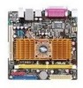
...Speaker connector (4- 1.2 1.2.1 Motherboard overview Motherboard layout Ensure that you install the motherboard into the holes indicated by circles to secure the motherboard to the rear part of the chassis. 12 3 4 5 17.1cm(6.75in) 67 KBMS KBPWR ATX12V COM Intel® Atom 330 Place this side towards the ... CHA_FAN CHASSIS Intel® SATA2 8 AUDIO CD USB56 ICH7 PRI_IDE USBPW5-8 USB78 SATA1 VIA VT1705 AAFP PCI1 F_PANEL SB_PWR 8Mb BIOS SPEAKER 9 16 4 15 14 13 12 11 10 Place four screws into the chassis in connector (4-pin CD) 1-8 ASUS AT3GC-I 1-2 Front...
...Speaker connector (4- 1.2 1.2.1 Motherboard overview Motherboard layout Ensure that you install the motherboard into the holes indicated by circles to secure the motherboard to the rear part of the chassis. 12 3 4 5 17.1cm(6.75in) 67 KBMS KBPWR ATX12V COM Intel® Atom 330 Place this side towards the ... CHA_FAN CHASSIS Intel® SATA2 8 AUDIO CD USB56 ICH7 PRI_IDE USBPW5-8 USB78 SATA1 VIA VT1705 AAFP PCI1 F_PANEL SB_PWR 8Mb BIOS SPEAKER 9 16 4 15 14 13 12 11 10 Place four screws into the chassis in connector (4-pin CD) 1-8 ASUS AT3GC-I 1-2 Front...
User Manual
Page 12
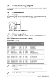
... SS/DD Brand Chip No. Visit the ASUS website at www.asus.com for the latest QVL. 1-3 Chapter 1: Product introduction The figure illustrates the location of the DDR2 DIMM socket: AT3GC-I DIMM1 AT3GC-I Motherboard Qualified Vendors List (QVL) DDR2-533MHz capability...one Double Data Rate 2 (DDR2) Dual Inline Memory Modules (DIMM) sockets. 1.3 Central Processing Unit (CPU) The motherboard comes with an onboard Intel® Atom 330 processor and a specially designed CPU heatsink. 1.4 System memory 1.4.1 Overview The motherboard comes with one module inserted into the DIMM socket.
... SS/DD Brand Chip No. Visit the ASUS website at www.asus.com for the latest QVL. 1-3 Chapter 1: Product introduction The figure illustrates the location of the DDR2 DIMM socket: AT3GC-I DIMM1 AT3GC-I Motherboard Qualified Vendors List (QVL) DDR2-533MHz capability...one Double Data Rate 2 (DDR2) Dual Inline Memory Modules (DIMM) sockets. 1.3 Central Processing Unit (CPU) The motherboard comes with an onboard Intel® Atom 330 processor and a specially designed CPU heatsink. 1.4 System memory 1.4.1 Overview The motherboard comes with one module inserted into the DIMM socket.


