

User Manual
Page 5
1.8 1.8.1 1-18 1-18 1.8.2 1-18 1.8.3 PCI 1-20 1.8.4 AGP 1-20 1.9 1-21 1.10 1.10.1 1-22 1-22 1.10.2 1-24 BIOS 2.1 BIOS 2-3 2.2 BIOS 2-4 2.3 Standard CMOS Features 2-6 2.4 Advanced BIOS Features 2-10 2.5 Integrated Peripherals 2-12 2.6 Power Management Setup 2-16 2.7 PC Health Status 2-18 2.8 2-20 2.8.1 Load Optimized Defaults 2-20 2.8.2 Supervisor Password 2-20 2.8.3 User Password 2-20 2.8.4 Save & Exit Setup 2-20 2.8.5 Exit Without Saving 2-20 5
1.8 1.8.1 1-18 1-18 1.8.2 1-18 1.8.3 PCI 1-20 1.8.4 AGP 1-20 1.9 1-21 1.10 1.10.1 1-22 1-22 1.10.2 1-24 BIOS 2.1 BIOS 2-3 2.2 BIOS 2-4 2.3 Standard CMOS Features 2-6 2.4 Advanced BIOS Features 2-10 2.5 Integrated Peripherals 2-12 2.6 Power Management Setup 2-16 2.7 PC Health Status 2-18 2.8 2-20 2.8.1 Load Optimized Defaults 2-20 2.8.2 Supervisor Password 2-20 2.8.3 User Password 2-20 2.8.4 Save & Exit Setup 2-20 2.8.5 Exit Without Saving 2-20 5

User Manual
Page 22
CPU 2. 3. 4. CPU_FAN1 1-14 CPU_FAN CPU_FAN GND CPU FAN PWR CPU FAN IN CPU FAN PWM ® CPU FAN Connector CPU_FAN Hardware monitoring errors CPU 1.6.3 1.
CPU 2. 3. 4. CPU_FAN1 1-14 CPU_FAN CPU_FAN GND CPU FAN PWR CPU FAN IN CPU FAN PWM ® CPU FAN Connector CPU_FAN Hardware monitoring errors CPU 1.6.3 1.

User Manual
Page 34
Serial ATA 7-pin SATA1, SATA2 Serial ATA SATA2 GND RSATA_RXN1 RSATA_RXP1 GND RSATA_TXN1 RSATA_TXP1 GND SATA1 ® GND RSATA_RXN2 RSATA_RXP2 GND RSATA_TXN2 RSATA_TXP2 GND Serial ATA SATA Connectors Serial ATA • Serial ATA Windows XP Service Pack 2 Windows 2000 Service Pack 4 • standard IDE mode SATA1 SATA2 Primary Serial ATA Master Slave SATA1 SATA2 Master Slave 1-26 3.
Serial ATA 7-pin SATA1, SATA2 Serial ATA SATA2 GND RSATA_RXN1 RSATA_RXP1 GND RSATA_TXN1 RSATA_TXP1 GND SATA1 ® GND RSATA_RXN2 RSATA_RXP2 GND RSATA_TXN2 RSATA_TXP2 GND Serial ATA SATA Connectors Serial ATA • Serial ATA Windows XP Service Pack 2 Windows 2000 Service Pack 4 • standard IDE mode SATA1 SATA2 Primary Serial ATA Master Slave SATA1 SATA2 Master Slave 1-26 3.

User Manual
Page 35
4. / 4-pin CPU_FAN, 3-pin CHA_FAN 350 740 8.88 1 2.22 26.64 /+12 +12V GND CHA_FAN GND +12V Rotation ® FAN Connectors CPU_FAN GND CPU FAN PWR CPU FAN IN CPU FAN PWM 5. 4-1 pin SPDIF1 S/PDIF S/ PDIF +5V SPDIFOUT GND ® SPDIF_OUT Digital Audio Connector 1-27
4. / 4-pin CPU_FAN, 3-pin CHA_FAN 350 740 8.88 1 2.22 26.64 /+12 +12V GND CHA_FAN GND +12V Rotation ® FAN Connectors CPU_FAN GND CPU FAN PWR CPU FAN IN CPU FAN PWM 5. 4-1 pin SPDIF1 S/PDIF S/ PDIF +5V SPDIFOUT GND ® SPDIF_OUT Digital Audio Connector 1-27

User Manual
Page 36
6. 20-pin ATXPWR1, 4-pin ATX12V1 ATX +12V • 20-pin ATX 12V PSU 250W • 4-pin ATX +12V • ® ATX Power Connectors ATX12V ATXPWR GND +12V DC GND +12V DC +12.0VDC +5VSB PWR_OK GND +5.0VDC GND +5.0VDC GND +3.3VDC +3.3VDC +5.0VDC +5.0VDC -5.0VDC GND GND GND PS_ON# GND -12.0VDC +3.3VDC 7. 10-1 pin FP_AUDIO / LINE_OUT_L/BLINE_OUT_L LINE_OUT_R/BLINE_OUT_R AGND +5VA BLINE_OUT_R BLINE_OUT_L MIC2 MICPWR Line out_R NC Line out_L 1-28 ® FP_AUDIO Front Panel Audio Connector
6. 20-pin ATXPWR1, 4-pin ATX12V1 ATX +12V • 20-pin ATX 12V PSU 250W • 4-pin ATX +12V • ® ATX Power Connectors ATX12V ATXPWR GND +12V DC GND +12V DC +12.0VDC +5VSB PWR_OK GND +5.0VDC GND +5.0VDC GND +3.3VDC +3.3VDC +5.0VDC +5.0VDC -5.0VDC GND GND GND PS_ON# GND -12.0VDC +3.3VDC 7. 10-1 pin FP_AUDIO / LINE_OUT_L/BLINE_OUT_L LINE_OUT_R/BLINE_OUT_R AGND +5VA BLINE_OUT_R BLINE_OUT_L MIC2 MICPWR Line out_R NC Line out_L 1-28 ® FP_AUDIO Front Panel Audio Connector
User Manual
Page 42
2.1 BIOS 2-3 2.2 BIOS 2-4 2.3 Standard CMOS Features 2-6 2.4 Advanced BIOS Features 2-10 2.5 Integrated Peripherals 2-12 2.6 Power Management Setup 2-16 2.7 PC Health Status 2-18 2.8 2-20 2.8.1 Load Optimized Defaults 2-20 2.8.2 Supervisor Password 2-20 2.8.3 User Password 2-20 2.8.4 Save & Exit Setup 2-20 2.8.5 Exit Without Saving 2-20 2-2 BIOS
2.1 BIOS 2-3 2.2 BIOS 2-4 2.3 Standard CMOS Features 2-6 2.4 Advanced BIOS Features 2-10 2.5 Integrated Peripherals 2-12 2.6 Power Management Setup 2-16 2.7 PC Health Status 2-18 2.8 2-20 2.8.1 Load Optimized Defaults 2-20 2.8.2 Supervisor Password 2-20 2.8.3 User Password 2-20 2.8.4 Save & Exit Setup 2-20 2.8.5 Exit Without Saving 2-20 2-2 BIOS
User Manual
Page 43
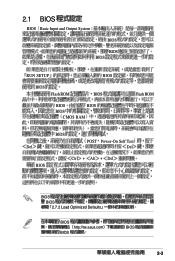
2.1 BIOS BIOS Basic Input and Output System BIOS BIOS BIOS RUN SETUP BIOS BIOS Flash ROM BIOS BIOS BIOS BIOS CMOS RAM Flash ROM Del BIOS BIOS POST Power-On Self Test Del Ctrl + Alt + Del BIOS BIOS 2.7.2 Load Optimized Defaults BIOS http://tw.asus.com BIOS BIOS 2-3
2.1 BIOS BIOS Basic Input and Output System BIOS BIOS BIOS RUN SETUP BIOS BIOS Flash ROM BIOS BIOS BIOS BIOS CMOS RAM Flash ROM Del BIOS BIOS POST Power-On Self Test Del Ctrl + Alt + Del BIOS BIOS 2.7.2 Load Optimized Defaults BIOS http://tw.asus.com BIOS BIOS 2-3
User Manual
Page 44
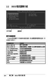
BIOS or or Exit ← or → (keypad arrow) ↑ or ↓ (keypad arrows) - (minus key) + (plus key) or spacebar or or BIOS 2-4 BIOS Award BIOS CMOS Setup Utility Standard BIOS Features Advanced BIOS Features Integrated Peripherals Power Management Setup PC Health Status Load Optimized Defaults Set Supervisor Password Set User Password Save & Exit Setup Exit Without Saving Esc : Quit F10 : Save & Exit Setup : Select Item F1 : General Help Time, Date, Hard Disk Type... 2.2 BIOS Phoenix -
BIOS or or Exit ← or → (keypad arrow) ↑ or ↓ (keypad arrows) - (minus key) + (plus key) or spacebar or or BIOS 2-4 BIOS Award BIOS CMOS Setup Utility Standard BIOS Features Advanced BIOS Features Integrated Peripherals Power Management Setup PC Health Status Load Optimized Defaults Set Supervisor Password Set User Password Save & Exit Setup Exit Without Saving Esc : Quit F10 : Save & Exit Setup : Select Item F1 : General Help Time, Date, Hard Disk Type... 2.2 BIOS Phoenix -
User Manual
Page 46
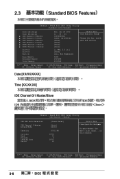
... Access Mode Capacity Cylinder Head Precomp Landing Zone Sector [Press Enter] [Auto] [Auto] 20021 MB 38792 16 0 38791 63 Select Menu Item Specific Help To auto-detect the HDD's size, head... on this channel : Move Enter:Select +/-/PU/PD:Value F10:Save ESC:Exit F1:General Help F5: Previous Values F6: Fail Safe Defaults F7: Optimized Defaults 2-6 BIOS Award BIOS CMOS Setup Utility Standard BIOS...
... Access Mode Capacity Cylinder Head Precomp Landing Zone Sector [Press Enter] [Auto] [Auto] 20021 MB 38792 16 0 38791 63 Select Menu Item Specific Help To auto-detect the HDD's size, head... on this channel : Move Enter:Select +/-/PU/PD:Value F10:Save ESC:Exit F1:General Help F5: Previous Values F6: Fail Safe Defaults F7: Optimized Defaults 2-6 BIOS Award BIOS CMOS Setup Utility Standard BIOS...

User Manual
Page 48
Award BIOS CMOS Setup Utility SATA Channel 2 Master SATA Auto-Detection Extended IDE Drive Access Mode Capacity Cylinder Head Precomp Landing Zone Sector [Press Enter] [Auto] [Auto] 20021 MB 38792 16 0 38791 63 Select Menu Item Specific Help To auto-detect the HDD's size, head... on this channel : Move Enter:Select +/-/PU/PD:Value F10:Save ESC:Exit F1:General Help F5: Previous Values F6...
Award BIOS CMOS Setup Utility SATA Channel 2 Master SATA Auto-Detection Extended IDE Drive Access Mode Capacity Cylinder Head Precomp Landing Zone Sector [Press Enter] [Auto] [Auto] 20021 MB 38792 16 0 38791 63 Select Menu Item Specific Help To auto-detect the HDD's size, head... on this channel : Move Enter:Select +/-/PU/PD:Value F10:Save ESC:Exit F1:General Help F5: Previous Values F6...
User Manual
Page 50
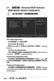
... BIOS CMOS Setup Utility Advanced BIOS Features CPU Feature Hard Disk Boot Priority First Boot Device Second Boot Device Third Boot Device Boot other Device Boot Up Floppy Seek Boot Up NumLock Status Security Option [Press Enter] [Press Enter] [Hard Disk] [CDROM] [Floppy] [Enabled] [Disabled] [On] [Setup] Select Menu Item Specific Help Select Hard Disk Boot Device Priority : Move Enter:Select +/-/PU/PD:Value F10:Save ESC:Exit F1:General Help F5: Previous Values F6: Fail Safe Defaults F7: Optimized Defaults CPU Feature [Press Enter] CPU Execute Disable Bit [Enabled] [Disabled] CPU...
... BIOS CMOS Setup Utility Advanced BIOS Features CPU Feature Hard Disk Boot Priority First Boot Device Second Boot Device Third Boot Device Boot other Device Boot Up Floppy Seek Boot Up NumLock Status Security Option [Press Enter] [Press Enter] [Hard Disk] [CDROM] [Floppy] [Enabled] [Disabled] [On] [Setup] Select Menu Item Specific Help Select Hard Disk Boot Device Priority : Move Enter:Select +/-/PU/PD:Value F10:Save ESC:Exit F1:General Help F5: Previous Values F6: Fail Safe Defaults F7: Optimized Defaults CPU Feature [Press Enter] CPU Execute Disable Bit [Enabled] [Disabled] CPU...
User Manual
Page 51
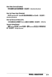
Boot Other Device [Enabled] Boot Up Floppy Seek [Disabled] [Enabled] BIOS [Disabled] [Enabled] Boot Up NumLock Status [On] NumLock Security Option[Setup] [Setup] BIOS [Setup] [System] [Enabled] [Disabled] 40 80 [System] [Off] [On] 2-11
Boot Other Device [Enabled] Boot Up Floppy Seek [Disabled] [Enabled] BIOS [Disabled] [Enabled] Boot Up NumLock Status [On] NumLock Security Option[Setup] [Setup] BIOS [Setup] [System] [Enabled] [Disabled] 40 80 [System] [Off] [On] 2-11
User Manual
Page 52
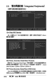
... Safe Defaults F7: Optimized Defaults IDE Primary ,Secondary Master/Slave PIO [Auto] PIO Programmed Input/Output Mode 0 Mode 4 [Mode 0] [Mode 1] [Mode 2] [Mode 3] [Mode 4] IDE [Auto] IDE Primary,Secondary Master/Slave UDMA [Auto] Ultra DMA [Disabled] IDE Ultra DMA [Disabled] [Auto] 2-12 BIOS 2.5 Integrated Peripherals Phoenix - Award BIOS CMOS Setup Utility Integrated Peripherals On-Chip IDE Device Onboard Device SuperIO Device [Press Enter] [Press Enter] [Press Enter] Select Menu Item Specific Help Onchip IDE Device Setup menu : Move Enter...
... Safe Defaults F7: Optimized Defaults IDE Primary ,Secondary Master/Slave PIO [Auto] PIO Programmed Input/Output Mode 0 Mode 4 [Mode 0] [Mode 1] [Mode 2] [Mode 3] [Mode 4] IDE [Auto] IDE Primary,Secondary Master/Slave UDMA [Auto] Ultra DMA [Disabled] IDE Ultra DMA [Disabled] [Auto] 2-12 BIOS 2.5 Integrated Peripherals Phoenix - Award BIOS CMOS Setup Utility Integrated Peripherals On-Chip IDE Device Onboard Device SuperIO Device [Press Enter] [Press Enter] [Press Enter] Select Menu Item Specific Help Onchip IDE Device Setup menu : Move Enter...
User Manual
Page 53
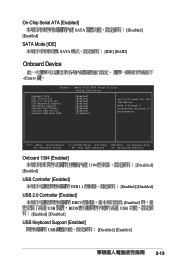
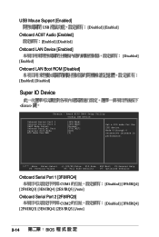
... Safe Defaults F7: Optimized Defaults Onboard 1394 [Enabled] [Enabled] 1394 [Disabled] USB Controller [Enabled] USB 1.1 [Enabled] [Disabled] USB 2.0 Controller [Enabled] EHCI USB BIOS [Enabled] [Disabled] [Enabled] USB USB Keyboard Support [Enabled] USB [Disabled] [Enabled] 2-13 Award BIOS CMOS Setup Utility Onchip IDE Device Onboard 1394 USB Controller USB 2.0 Controller USB Keyboard Support USB Mouse Support Onboard AC97 Audio Onboard LAN Device Onboard LAN Boot ROM [Enabled] [Enabled] [Enabled] [Enabled] [Enabled] [Enabled] [Enabled] [Disabled] Set a PIO mode for the...
... Safe Defaults F7: Optimized Defaults Onboard 1394 [Enabled] [Enabled] 1394 [Disabled] USB Controller [Enabled] USB 1.1 [Enabled] [Disabled] USB 2.0 Controller [Enabled] EHCI USB BIOS [Enabled] [Disabled] [Enabled] USB USB Keyboard Support [Enabled] USB [Disabled] [Enabled] 2-13 Award BIOS CMOS Setup Utility Onchip IDE Device Onboard 1394 USB Controller USB 2.0 Controller USB Keyboard Support USB Mouse Support Onboard AC97 Audio Onboard LAN Device Onboard LAN Boot ROM [Enabled] [Enabled] [Enabled] [Enabled] [Enabled] [Enabled] [Enabled] [Disabled] Set a PIO mode for the...
User Manual
Page 54
... Enter:Select +/-/PU/PD:Value F10:Save ESC:Exit F1:General Help F5: Previous Values F6: Fail Safe Defaults F7: Optimized Defaults Onboard Serial Port 1 [3F8/IRQ4] COM1 [2F8/IRQ3] [3E8/IRQ4] [2E8/IRQ3] [Auto] Onboard Serial Port 2 [2F8/IRQ3] COM2 [2F8/IRQ3] [3E8/IRQ4] [2E8/IRQ3] [Auto] [Disabled] [3F8/IRQ4] [Disabled] [3F8/IRQ4] 2-14 BIOS USB Mouse Support [Enabled] USB Onboard AC97 Audio [Enabled] [Enabled] [Disabled] Onboard LAN Device [Enabled] [Enabled] Onboard LAN Boot ROM [Disabled] [Disabled] [Enabled] [Disabled] [Enabled] [Disabled...
... Enter:Select +/-/PU/PD:Value F10:Save ESC:Exit F1:General Help F5: Previous Values F6: Fail Safe Defaults F7: Optimized Defaults Onboard Serial Port 1 [3F8/IRQ4] COM1 [2F8/IRQ3] [3E8/IRQ4] [2E8/IRQ3] [Auto] Onboard Serial Port 2 [2F8/IRQ3] COM2 [2F8/IRQ3] [3E8/IRQ4] [2E8/IRQ3] [Auto] [Disabled] [3F8/IRQ4] [Disabled] [3F8/IRQ4] 2-14 BIOS USB Mouse Support [Enabled] USB Onboard AC97 Audio [Enabled] [Enabled] [Disabled] Onboard LAN Device [Enabled] [Enabled] Onboard LAN Boot ROM [Disabled] [Disabled] [Enabled] [Disabled] [Enabled] [Disabled...
User Manual
Page 56
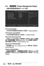
Award BIOS CMOS Setup Utility Power Management Setup ACPI Function ACPI Suspend Type Off by Power Button Resume by PCI PME Resume by Ring Resume by USB(S3) Resume by Alarm x Date (of Month) Alarm x Time (hh:mm:ss) Alarm State after Power Failure [Enabled] [S3(STR)] [Instant-Off] [Disabled] [Disabled] [Disabled] [Disabled] 0 0 : 0 : 0 [off] Select Menu Item Specific Help Select the ACPI state used for System Suspend. : Move Enter:Select +/-/PU/PD:Value F10...
Award BIOS CMOS Setup Utility Power Management Setup ACPI Function ACPI Suspend Type Off by Power Button Resume by PCI PME Resume by Ring Resume by USB(S3) Resume by Alarm x Date (of Month) Alarm x Time (hh:mm:ss) Alarm State after Power Failure [Enabled] [S3(STR)] [Instant-Off] [Disabled] [Disabled] [Disabled] [Disabled] 0 0 : 0 : 0 [off] Select Menu Item Specific Help Select the ACPI state used for System Suspend. : Move Enter:Select +/-/PU/PD:Value F10...

User Manual
Page 57
hour =0 =23 minutes =0 =59 seconds =0 =59 State after Power Failure [off] [Off] [On] [Former-Sts] 2-17 tab 4. 5. tab 6. Resume by USB (S3) [Enabled] USB [Disabled] [Enabled] Resume by Alarm [Disabled] RTC [Disabled] [Enabled] Day of Month Alarm [NA] RTC [Max=31] Time (hh:mm:ss) Alarm [0 : 0 : 0] [Enabled] [Min=0] 1. 2. 3.
hour =0 =23 minutes =0 =59 seconds =0 =59 State after Power Failure [off] [Off] [On] [Former-Sts] 2-17 tab 4. 5. tab 6. Resume by USB (S3) [Enabled] USB [Disabled] [Enabled] Resume by Alarm [Disabled] RTC [Disabled] [Enabled] Day of Month Alarm [NA] RTC [Max=31] Time (hh:mm:ss) Alarm [0 : 0 : 0] [Enabled] [Min=0] 1. 2. 3.
User Manual
Page 58
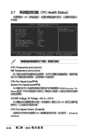
... Phoenix - Award BIOS CMOS Setup Utility PC Health Status CPU Temperature MB Temperature CPU Fan Speed System Fan Speed VCORE Voltage 3.3V Voltage +5V in +13V in CPU FAN SPEED CONTROL Start Up Temperature(oC) Full Speed Temperature(oC) Start Up PWM Slope Select PWM/oC 38oC 37oC 3835 RPM 0 RPM 1.50 V 3.34 V 5.19 V 11.61 V [Enabled] [54] [66] [45] [4 PWM/oC] Select Menu Item Specific Help : Move Enter:Select +/-/PU...
... Phoenix - Award BIOS CMOS Setup Utility PC Health Status CPU Temperature MB Temperature CPU Fan Speed System Fan Speed VCORE Voltage 3.3V Voltage +5V in +13V in CPU FAN SPEED CONTROL Start Up Temperature(oC) Full Speed Temperature(oC) Start Up PWM Slope Select PWM/oC 38oC 37oC 3835 RPM 0 RPM 1.50 V 3.34 V 5.19 V 11.61 V [Enabled] [54] [66] [45] [4 PWM/oC] Select Menu Item Specific Help : Move Enter:Select +/-/PU...
User Manual
Page 60
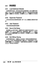
2.8 2.8.1 Load Optimized Defaults Enter BIOS [OK] [Cancel] BIOS 2.8.2 Supervisor Password 2.8.3 User Password 2.8.4 Save & Exit Setup BIOS BIOS Enter CMOS BIOS 2.8.5 Exit Without Saving Enter BIOS [Cancel] BIOS BIOS CMOS [Yes] [Cancel] [OK] CMOS 2-20 BIOS
2.8 2.8.1 Load Optimized Defaults Enter BIOS [OK] [Cancel] BIOS 2.8.2 Supervisor Password 2.8.3 User Password 2.8.4 Save & Exit Setup BIOS BIOS Enter CMOS BIOS 2.8.5 Exit Without Saving Enter BIOS [Cancel] BIOS BIOS CMOS [Yes] [Cancel] [OK] CMOS 2-20 BIOS

User Manual
Page 64
3.2.2 Drivers menu ASUS InstAll VIA Chipset VIA S3G Realtek AC97 ASUS InstAll VIA VIA S3G Realtek AC97 Realtek RTL8169/8100 Realtek RTL8169/8100 USB 2.0 USB2.0 3-4
3.2.2 Drivers menu ASUS InstAll VIA Chipset VIA S3G Realtek AC97 ASUS InstAll VIA VIA S3G Realtek AC97 Realtek RTL8169/8100 Realtek RTL8169/8100 USB 2.0 USB2.0 3-4


