A8V-E SE User's Manual for English Edition
Page 11
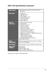
xi A8V-E SE specifications summary BIOS features Rear panel Internal connectors...1 x CPU fan connector 1 x Power fan connector 1 x Chassis fan connector 1 x Serial port connector (COM port) 1 x 24-pin ATX power connector 1 x 4-pin ATX 12 V power connector 2 x USB 2.0 connectors for 4 additional USB 2.0 ports 1 x GAME/MIDI connector 1 x Chassis intrusion connector 1 ... connectors System panel connector ATX power supply (with 24-pin and 4-pin 12 V plugs) ATX 12 V 2.0 compliant ATX form factor: 12 in x 9.6 in (30.5 cm x 24.4 cm) Device drivers ASUS PC Probe ASUS Live Update Utility Antivirus ...
xi A8V-E SE specifications summary BIOS features Rear panel Internal connectors...1 x CPU fan connector 1 x Power fan connector 1 x Chassis fan connector 1 x Serial port connector (COM port) 1 x 24-pin ATX power connector 1 x 4-pin ATX 12 V power connector 2 x USB 2.0 connectors for 4 additional USB 2.0 ports 1 x GAME/MIDI connector 1 x Chassis intrusion connector 1 ... connectors System panel connector ATX power supply (with 24-pin and 4-pin 12 V plugs) ATX 12 V 2.0 compliant ATX form factor: 12 in x 9.6 in (30.5 cm x 24.4 cm) Device drivers ASUS PC Probe ASUS Live Update Utility Antivirus ...

A8V-E SE User's Manual for English Edition
Page 18
... it on a grounded antistatic pad or in the bag that came with the component. • Before you install or remove any component, ensure that the ATX power supply is switched off mode. Onboard LEDs The motherboard comes with a green standby power LED that lights up to avoid touching the ICs on... supply case, before removing or plugging in any motherboard component. Failure to do so may cause severe damage to the motherboard, peripherals, and/or components. A8V-E SE ® A8V-E SE Onboard LED SB_PWR ON Standby Power OFF Powered Off 1-6 Chapter 1: Product introduction
... it on a grounded antistatic pad or in the bag that came with the component. • Before you install or remove any component, ensure that the ATX power supply is switched off mode. Onboard LEDs The motherboard comes with a green standby power LED that lights up to avoid touching the ICs on... supply case, before removing or plugging in any motherboard component. Failure to do so may cause severe damage to the motherboard, peripherals, and/or components. A8V-E SE ® A8V-E SE Onboard LED SB_PWR ON Standby Power OFF Powered Off 1-6 Chapter 1: Product introduction

A8V-E SE User's Manual for English Edition
Page 33
This feature requires an ATX power supply that can supply at least 1A on the +5VSB lead for each USB port; USBPW34 USBPW12 12 23 A8V-E SE ® A8V-E SE USB device wake-up +5V (Default) +5VSB USBPW78 USBPW56 2 1 +5V (Default) 3 2 +5VSB • The USB device wake... supply that can provide 500mA on the +5VSB lead, and a corresponding setting in reduced power mode). A8V-E SE KBPWR 2 1 +5V (Default) 2 1 +5VSB ® A8V-E SE Keyboard power setting ASUS A8V-E SE 1-21 Refer of the Keyboard power (3-pin KBPWR) This jumper allows you press a key on the keyboard...
This feature requires an ATX power supply that can supply at least 1A on the +5VSB lead for each USB port; USBPW34 USBPW12 12 23 A8V-E SE ® A8V-E SE USB device wake-up +5V (Default) +5VSB USBPW78 USBPW56 2 1 +5V (Default) 3 2 +5VSB • The USB device wake... supply that can provide 500mA on the +5VSB lead, and a corresponding setting in reduced power mode). A8V-E SE KBPWR 2 1 +5V (Default) 2 1 +5VSB ® A8V-E SE Keyboard power setting ASUS A8V-E SE 1-21 Refer of the Keyboard power (3-pin KBPWR) This jumper allows you press a key on the keyboard...

A8V-E SE User's Manual for English Edition
Page 40
.... 9 . otherwise, the system will not boot up if the power is recommended for an ATX power supply plugs. EATXPWR +3 Volts -12 Volts ATX12V Ground PSON# A8V-E SE GND +12V DC GND Ground +12V DC Ground Ground -5 Volts ® +5 Volts +5 Volts A8V-E SE ATX power connectors +5 Volts Ground +3 Volts +3 Volts Ground +5 Volts Ground +5 Volts Ground Power OK...
.... 9 . otherwise, the system will not boot up if the power is recommended for an ATX power supply plugs. EATXPWR +3 Volts -12 Volts ATX12V Ground PSON# A8V-E SE GND +12V DC GND Ground +12V DC Ground Ground -5 Volts ® +5 Volts +5 Volts A8V-E SE ATX power connectors +5 Volts Ground +3 Volts +3 Volts Ground +5 Volts Ground +5 Volts Ground Power OK...
A8V-E SE User's Manual for English Edition
Page 42
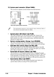
...The speaker allows you turn on the BIOS settings. ExtSMI# Ground PWR Ground Reset Ground IDE LED RESET ® SMI PWR * Requires an ATX power supply. Connect the chassis power LED cable to hear system beeps and warnings. • Hard disk drive activity (Red 2-pin IDE_LED) This... in sleep mode. • System warning speaker (Orange 4-pin SPEAKER) This 4-pin connector is for the chassis-mounted system warning speaker. 12. A8V-E SE System panel connector The sytem panel connector is for easy connection. Refer to the HDD. • Power/Soft-off the system power. 1-30 Chapter...
...The speaker allows you turn on the BIOS settings. ExtSMI# Ground PWR Ground Reset Ground IDE LED RESET ® SMI PWR * Requires an ATX power supply. Connect the chassis power LED cable to hear system beeps and warnings. • Hard disk drive activity (Red 2-pin IDE_LED) This... in sleep mode. • System warning speaker (Orange 4-pin SPEAKER) This 4-pin connector is for the chassis-mounted system warning speaker. 12. A8V-E SE System panel connector The sytem panel connector is for easy connection. Refer to the HDD. • Power/Soft-off the system power. 1-30 Chapter...

A8V-E SE User's Manual for English Edition
Page 72
... Password Max 8 numbers. Configuration options: [Disabled] [Enabled] Power On By RTC Alarm [Disabled] Allows you to turn on the +5VSB lead. This feature requires an ATX power supply that provides at least 1A on the system through a PCI LAN or modem card. Configuration options: [Disabled] [Enabled] 2-30 Chapter 2: BIOS setup F1... the external modem receives a call while the computer is set specific keys on the PS/2 keyboard to turn on the system. This feature requires an ATX power supply that provides at least 1A on the +5VSB lead. This feature requires an...
... Password Max 8 numbers. Configuration options: [Disabled] [Enabled] Power On By RTC Alarm [Disabled] Allows you to turn on the +5VSB lead. This feature requires an ATX power supply that provides at least 1A on the system through a PCI LAN or modem card. Configuration options: [Disabled] [Enabled] 2-30 Chapter 2: BIOS setup F1... the external modem receives a call while the computer is set specific keys on the PS/2 keyboard to turn on the system. This feature requires an ATX power supply that provides at least 1A on the +5VSB lead. This feature requires an...

