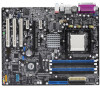
A8V-E SE User's Manual for English Edition
Page 13
This chapter describes the motherboard features and the new technologies it supports. 1Product introduction ASUS A8V-E SE 1-1
A8V-E SE User's Manual for English Edition
Page 14
... technologies, making it , check the items in the long line of the above items is damaged or missing, contact your motherboard package for buying an ASUS® A8V-E SE motherboard! Thank you start installing the motherboard, and hardware devices on it another standout in your package with the list below. 1.2 Package contents Check...
A8V-E SE User's Manual for English Edition
Page 15
... DDR memory support Employing the Double Data Rate (DDR) memory technology, the motherboard supports up to 48 times faster than other existing technologies. See page 1-9. ASUS A8V-E SE 1-3 See page 1-9. See page 1-13. 1.3 Special features 1.3.1 Product highlights AMD Dual-Core Architecture The motherboard supports AMD dual-core processors containing two physical CPU cores...
A8V-E SE User's Manual for English Edition
Page 17
...the bootup process, AI NET 2 immediately diagnoses the LAN cable(s) and reports shorts and faults up to buy a replacement ROM chip. ASUS Q-Fan technology The ASUS Q-Fan technology smartly adjusts the fan speeds according to the system loading to restore the original BIOS data from the support CD in the... AI NET 2 AI NET 2 is a BIOS-based diagnostic tool that detects and reports Ethernet cable faults and shorts. ASUS A8V-E SE 1-5 PEG Link mode This feature allows you to personalize and add style to your system configuration for overclocking aficionados, this utility, you can...
A8V-E SE User's Manual for English Edition
Page 19
... holes indicated by circles to secure the motherboard to the chassis. Do not overtighten the screws! Place this side towards the rear of the chassis A8V-E SE ® ASUS A8V-E SE 1-7 Make sure to do so can damage the motherboard. Failure to unplug the power cord before installing or removing the motherboard. Doing so can...
A8V-E SE User's Manual for English Edition
Page 21
... data paths. Gold triangle 1.6.2 Installling the CPU To install a CPU: 1. 1.6 Central Processing Unit (CPU) 1.6.1 Overview The motherboard comes with gold triangle) on the CPU. ASUS A8V-E SE 1-9 A8V-E SE ® A8V-E SE CPU Socket 939 Before installing the CPU, make sure that the socket box is facing towards you and the load lever is on the socket...
A8V-E SE User's Manual for English Edition
Page 23
... bracket lock Retention Module Base Your boxed CPU heatsink and fan assembly should come with installation instructions for the CPU, heatsink, and the retention mechanism. ASUS A8V-E SE 1-11 1.6.3 Installing the heatsink and fan The AMD Athlon™ 64, AMD Athlon™ 64FX or AMD Athlon™ 64 X2 processors require a specially designed...
A8V-E SE User's Manual for English Edition
Page 25
ASUS A8V-E SE 1-13 Refer to chipset resource allocation, the system may install 64MB, 128MB, 256 MB, 512 MB and 1 GB unbuffered ECC or non-ECC DDR DIMMs ... 184-pin Double Data Rate (DDR) Dual Inline Memory Modules (DIMM) sockets. The following figure illustrates the location of the sockets: DIMM_A1 DIMM_A2 DIMM_B1 DIMM_B2 A8V-E SE ® A8V-E SE 184-pin DDR DIMM sockets Channel Channel A Channel B Sockets DIMM_A1 and DIMM_A2 DIMM_B1 and DIMM_B2 1.7.2 Memory Configurations You may detect less than 4 GB of...
A8V-E SE User's Manual for English Edition
Page 27
B - Visit the ASUS website (www.asus.com) for 4 modules inserted into the yellow and black slots as one module inserted into either the yellow slots or the black slots as two ...pairs of Dual-channel memory configuration. Double Sided DIMM Support: A - supports on pair of modules inserted into either slot, in a Single-channel memory configuration. ASUS A8V-E SE 1-15 supports one pair of Dual-channel memory configuration. DDR400 Qualified Vendors List Size Vendor Model 256MB 512MB 1024MB 512MB 256MB 256MB 512MB 256MB 512MB...
A8V-E SE User's Manual for English Edition
Page 29
... x16 card. 1.8.1 Installing an expansion card To install an expansion card: 1. Keep the screw for the expansion card. Install the software drivers for later use . ASUS A8V-E SE 1-17 Failure to do so may need to install expansion cards. Remove the bracket opposite the slot that you removed earlier. 6. Align the card connector...
A8V-E SE User's Manual for English Edition
Page 31
... slot. 1.8.6 PCI Express x1 slot This motherboard supports PCI Express x1 network cards, SCSI cards and other cards that comply with the PCI Express specifications. ASUS A8V-E SE 1-19 The figure shows a LAN card installed on a PCI slot. 1.8.5 PCI Express x16 slot This motherboard supports PCI Express x16 graphic cards that comply with...
A8V-E SE User's Manual for English Edition
Page 33
This feature requires an ATX power supply that can supply at least 1A on the keyboard (the default is the Space Bar). A8V-E SE KBPWR 2 1 +5V (Default) 2 1 +5VSB ® A8V-E SE Keyboard power setting ASUS A8V-E SE 1-21 Refer of the otherwise, the system would not power up. • The total current consumed must NOT exceed the power...
A8V-E SE User's Manual for English Edition
Page 35
... an FDD cable with a covered Pin 5. The Pin 5 on the floppy ribbon cable to PIN 1. PIN 1 A8V-E SE Floppy disk drive connector ASUS A8V-E SE 1-23 U S B 2 . 0 p o r t s 1 a n d 2 . This port connects an external audio output device via a coaxial S/PDIF cable. 1 2 . P S / 2 k e y b o a r d p o r t ( p u r p l e ) . A8V-E DELUXE ® FLOPPY NOTE: Orient the red markings on the connector is for a PS/2 mouse. 1.10.2 Internal...
A8V-E SE User's Manual for English Edition
Page 37
... JBOD) is available only if you are for the Serial ATA signal cables for a serial (COM) port. ASUS A8V-E SE 1-25 Serial port connector (10-1 pin COM1) This connector is purchased separately. A8V-E SE ® COM1 PIN 1 A8V-E SE COM port connector The Serial port module is for Serial ATA hard disk drives. Serial ATA connectors (7-pin...
A8V-E SE User's Manual for English Edition
Page 39
Line out_L NC Line out_R MICPWR MIC2 A8V-E SE ® FP_AUDIO A8V-E SE Front panel audio connector ASUS A8V-E SE BLINE_OUT_L BLINE_OUT_R +5VA AGND 1-27 7 . Doing so will damage the motherboard! USB+5V USB_P8USB_P8+ GND NC USB+5V USB_P6USB_P6+ GND NC USB+5V USB_P7USB_P7+ GND A8V-E SE ® USB56 1 A8V-E SE USB 2.0 connectors USB78 1 USB+5V USB_P5USB_P5+ GND The USB/GAME port...
A8V-E SE User's Manual for English Edition
Page 41
...intend to this connector when a chassis component is for playing or editing audio files. +5V J2B1 J2CX MIDI_OUT J2CY J2B2 MIDI_IN A8V-E SE ® A8V-E SE Game connector GAME +5V J1B1 J1CX GND GND J1CY J1B2 +5V The USB/GAME port module is purchased separately. 11. ...intrusion sensor or switch sends a high-level signal to use the chassis intrusion detection feature. +5VSB_MB Chassis Signal GND A8V-E SE CHASSIS ® (Default) A8V-E SE Chassis alarm lead ASUS A8V-E SE 1-29 The GAME/MIDI port connects a joystick or game pad for playing games, and MIDI devices for a chassis-...
A8V-E SE User's Manual for English Edition
Page 43
This chapter tells how to change the system settings through the BIOS Setup menus. Detailed descriptions of the BIOS parameters are also provided. 2 BIOS setup ASUS A8V-E SE 2-1
A8V-E SE User's Manual for English Edition
Page 45
... to avoid loading the wrong BIOS file. 2. Copy the AwardBIOS Flash Utility (awdflash.exe) from the ASUS web site. When the A : > appears, replace the bootable floppy disk with the latest BIOS file. 3. For K8T890-8237-A8V-E-00 DATE: 09/10/2004 Flash Type - E _ S E . Boot the system in the floppy disk to the... or the latest motherboard BIOS file to update the BIOS using the AwardBIOS Flash Utility. Rename the file to a floppy disk. B I N and save it to A 8 V - ASUS A8V-E SE 2-3 All Rights Reserved BIOS Flash Utility screen appears. e.
A8V-E SE User's Manual for English Edition
Page 47
... to 6 of the previous section. 2. All Rights Reserved For K8T890-8237-A8V-E-00 DATE: 09/10/2004 Flash Type - ASUS A8V-E SE 2-5 Follow steps 1 to the BIOS flashing process. All Rights Reserved For K8T890-8237-A8V-E-00 DATE: 09/10/2004 Flash Type - The following screen Flash Type ...- AwardBIOS Flash Utility for ASUS V1.01 (C) Phoenix Technologies Ltd. PMC ...
A8V-E SE User's Manual for English Edition
Page 49
...file. BIOS ROM checksum error Detecting IDE ATAPI device... Fail Detecting floppy drive A media... Doing so can cause system boot failure! 4. ASUS A8V-E SE 2-7 The utility displays the following message and automatically checks the floppy disk for the original or updated BIOS file. The recovered BIOS may ... to download the latest BIOS file. Found CDROM, try to Boot from the optical drive, then turn on the system. 2. Visit the ASUS website (www.asus.com) to the floppy disk drive. 3. Award BootBlock BIOS v1.0 Copyright (c) 2000, Award Software, Inc. Restart the system after the...