
A8V Deluxe User's Manual
Page 25
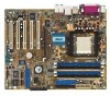
...Motherboard layout PS/2KBMS T: Mouse B: Keyboard KBPWR SPDIF_O SPDIF_O2 ATX12V 24.5cm (9.6in) CPU_FAN ATX Power Connector DDR DIMM_B1 (64 bit,184-pin module) DDR DIMM_B2 (64 bit,184-pin module) DDR DIMM_A1 (64 bit,184-pin module) DDR DIMM_A2 (64 bit,184-pin module) Socket 939... Graphics Port (AGP) PRI_IDE Marvell Gigabit LAN CD Realtek ALC850 AUX FP_AUDIO PCI1 PCI2 PCI3 PCI4 A8V PCI5 FLOPPY ® CR2032 3V Lithium Cell CMOS Power VIA VT8237 PRI_RAID SATA2 SATA1 CHA_FAN Promise ...SW ATX Power IDE_LED Switch* * Requires an ATX power supply. ASUS A8V Deluxe motherboard 2-3
...Motherboard layout PS/2KBMS T: Mouse B: Keyboard KBPWR SPDIF_O SPDIF_O2 ATX12V 24.5cm (9.6in) CPU_FAN ATX Power Connector DDR DIMM_B1 (64 bit,184-pin module) DDR DIMM_B2 (64 bit,184-pin module) DDR DIMM_A1 (64 bit,184-pin module) DDR DIMM_A2 (64 bit,184-pin module) Socket 939... Graphics Port (AGP) PRI_IDE Marvell Gigabit LAN CD Realtek ALC850 AUX FP_AUDIO PCI1 PCI2 PCI3 PCI4 A8V PCI5 FLOPPY ® CR2032 3V Lithium Cell CMOS Power VIA VT8237 PRI_RAID SATA2 SATA1 CHA_FAN Promise ...SW ATX Power IDE_LED Switch* * Requires an ATX power supply. ASUS A8V Deluxe motherboard 2-3

A8V Deluxe User's Manual
Page 28
... the CPU. This mark should match a specific corner on the motherboard. 2-6 Chapter 2: Hardware information Take note of these steps to ensure correct installation. The 128-bit-wide data paths of the marked corner (with a surface mount 939-pin Zero Insertion Force (ZIF) socket designed for the AMD Athlon™ 64FX or AMD Athlon...
... the CPU. This mark should match a specific corner on the motherboard. 2-6 Chapter 2: Hardware information Take note of these steps to ensure correct installation. The 128-bit-wide data paths of the marked corner (with a surface mount 939-pin Zero Insertion Force (ZIF) socket designed for the AMD Athlon™ 64FX or AMD Athlon...

A8V User Manual
Page 25
...Motherboard layout PS/2KBMS T: Mouse B: Keyboard KBPWR SPDIF_O SPDIF_O2 ATX12V 24.5cm (9.6in) CPU_FAN ATX Power Connector DDR DIMM_B1 (64 bit,184-pin module) DDR DIMM_B2 (64 bit,184-pin module) DDR DIMM_A1 (64 bit,184-pin module) DDR DIMM_A2 (64 bit,184-pin module) Socket 939... Graphics Port (AGP) PRI_IDE Marvell Gigabit LAN CD Realtek ALC850 AUX FP_AUDIO PCI1 PCI2 PCI3 PCI4 A8V PCI5 FLOPPY ® CR2032 3V Lithium Cell CMOS Power VIA VT8237 PRI_RAID SATA2 SATA1 CHA_FAN Promise ...SW ATX Power IDE_LED Switch* * Requires an ATX power supply. ASUS A8V Deluxe motherboard 2-3
...Motherboard layout PS/2KBMS T: Mouse B: Keyboard KBPWR SPDIF_O SPDIF_O2 ATX12V 24.5cm (9.6in) CPU_FAN ATX Power Connector DDR DIMM_B1 (64 bit,184-pin module) DDR DIMM_B2 (64 bit,184-pin module) DDR DIMM_A1 (64 bit,184-pin module) DDR DIMM_A2 (64 bit,184-pin module) Socket 939... Graphics Port (AGP) PRI_IDE Marvell Gigabit LAN CD Realtek ALC850 AUX FP_AUDIO PCI1 PCI2 PCI3 PCI4 A8V PCI5 FLOPPY ® CR2032 3V Lithium Cell CMOS Power VIA VT8237 PRI_RAID SATA2 SATA1 CHA_FAN Promise ...SW ATX Power IDE_LED Switch* * Requires an ATX power supply. ASUS A8V Deluxe motherboard 2-3
A8V User Manual
Page 28
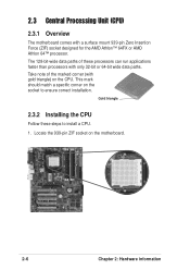
Take note of these steps to ensure correct installation. 2.3 Central Processing Unit (CPU) 2.3.1 Overview The motherboard comes with gold triangle) on the CPU. Gold triangle 2.3.2 Installing the CPU Follow these processors can run applications faster than ... of the marked corner (with a surface mount 939-pin Zero Insertion Force (ZIF) socket designed for the AMD Athlon™ 64FX or AMD Athlon 64™ processor. Locate the 939-pin ZIF socket on the socket to install a CPU. 1. This mark should match a specific corner on the motherboard. 2-6 Chapter 2: Hardware information
Take note of these steps to ensure correct installation. 2.3 Central Processing Unit (CPU) 2.3.1 Overview The motherboard comes with gold triangle) on the CPU. Gold triangle 2.3.2 Installing the CPU Follow these processors can run applications faster than ... of the marked corner (with a surface mount 939-pin Zero Insertion Force (ZIF) socket designed for the AMD Athlon™ 64FX or AMD Athlon 64™ processor. Locate the 939-pin ZIF socket on the socket to install a CPU. 1. This mark should match a specific corner on the motherboard. 2-6 Chapter 2: Hardware information


