
Motherboard DIY Troubleshooting Guide
Page 4
...Memory Installation 26 3.6 Central Processing Unit (CPU 27 3.7 Expansion Cards 28 3.7.1 Installing an Expansion Card 28 3.7.2 Assigning IRQs for Expansion Cards 29 3.7.3 Accelerated Graphics Port (AGP) Pro Slot 30 3.7.4 Advanced Communication Riser (ACR) Slot 30 3.8 Connectors 31 3.8.1 External Connectors 31 3.9 Starting Up the First Time 44 4. FEATURES 8 2.1 ASUS A7V266... Updating BIOS Procedures 47 4.2 BIOS Setup Program 49 4.2.1 BIOS Menu Bar 50 4.2.2 Legend Bar 50 4 ASUS A7V266 User's Manual INTRODUCTION 7 1.1 How This Manual Is Organized 7 1.2 Item Checklist 7 2.
...Memory Installation 26 3.6 Central Processing Unit (CPU 27 3.7 Expansion Cards 28 3.7.1 Installing an Expansion Card 28 3.7.2 Assigning IRQs for Expansion Cards 29 3.7.3 Accelerated Graphics Port (AGP) Pro Slot 30 3.7.4 Advanced Communication Riser (ACR) Slot 30 3.8 Connectors 31 3.8.1 External Connectors 31 3.9 Starting Up the First Time 44 4. FEATURES 8 2.1 ASUS A7V266... Updating BIOS Procedures 47 4.2 BIOS Setup Program 49 4.2.1 BIOS Menu Bar 50 4.2.2 Legend Bar 50 4 ASUS A7V266 User's Manual INTRODUCTION 7 1.1 How This Manual Is Organized 7 1.2 Item Checklist 7 2.

Motherboard DIY Troubleshooting Guide
Page 8
... complies with three root hubs for home PCs, workstations and servers. FEATURES 2.1 ASUS A7V266 Motherboard The ASUS A7V266 motherboard is targeted diversely for six USB ports. • PC2100 / PC1600 DDR Support: Equipped with three Double Data Rate Dual Inline Memory Module (DDR DIMM) sockets to support up to 3GB of frequency and Vcore voltage through...
... complies with three root hubs for home PCs, workstations and servers. FEATURES 2.1 ASUS A7V266 Motherboard The ASUS A7V266 motherboard is targeted diversely for six USB ports. • PC2100 / PC1600 DDR Support: Equipped with three Double Data Rate Dual Inline Memory Module (DDR DIMM) sockets to support up to 3GB of frequency and Vcore voltage through...
Motherboard DIY Troubleshooting Guide
Page 10
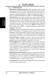
...the onboard IDE bus master controller triples the UltraDMA/33 burst transfer rate. The chip supports software access to the memory and processor. 10 ASUS A7V266 User's Manual Color-coded connectors and descriptive icons make identification easy as Windows 98. • Smartcard Reader Connector:...-3/DTS via SPDIF. FEATURES 2.1.2 Performance • DDR DRAM Optimized Performance: This motherboard supports a new generation memory, Double Data Rate (DDR) Dynamic Random Access Memory (DDR DRAM). To fully utilize the ACPI benefits, use an ACPI-supported OS such as required by executing...
...the onboard IDE bus master controller triples the UltraDMA/33 burst transfer rate. The chip supports software access to the memory and processor. 10 ASUS A7V266 User's Manual Color-coded connectors and descriptive icons make identification easy as Windows 98. • Smartcard Reader Connector:...-3/DTS via SPDIF. FEATURES 2.1.2 Performance • DDR DRAM Optimized Performance: This motherboard supports a new generation memory, Double Data Rate (DDR) Dynamic Random Access Memory (DDR DRAM). To fully utilize the ACPI benefits, use an ACPI-supported OS such as required by executing...

Motherboard DIY Troubleshooting Guide
Page 11
... their computers anywhere. • Temperature Monitoring and Alert: CPU temperature is necessary to be monitored for more than 4 seconds when the system is kept in memory on the BIOS or OS setting (See PWR Button < 4 Secs in sleep mode. FEATURES Intelligence 2. This function reduces both energy consumption and system noise, and... modem): This allows a computer to ensure proper system configuration and management. • Chassis Intrusion Detection: Supports chassis-intrusion monitoring through an internal or external modem. ASUS A7V266 User's Manual 11
... their computers anywhere. • Temperature Monitoring and Alert: CPU temperature is necessary to be monitored for more than 4 seconds when the system is kept in memory on the BIOS or OS setting (See PWR Button < 4 Secs in sleep mode. FEATURES Intelligence 2. This function reduces both energy consumption and system noise, and... modem): This allows a computer to ensure proper system configuration and management. • Chassis Intrusion Detection: Supports chassis-intrusion monitoring through an internal or external modem. ASUS A7V266 User's Manual 11

Motherboard DIY Troubleshooting Guide
Page 12
...VIA® VT8366 North Bridge 1 VIA® VT8233 South Bridge 9 ASUS System Monitor controller 7 C-Media® 6 Channel CMI8738 PCI audio controller 13 Multi-I/O controller 18 2Mbit Programmable Flash EEPROM 17 Main Memory Maximum 3GB support 3 DDR DIMM Sockets 4 Expansion Slots 5 PCI Slots ... 13 1 ASUS iPanel Audio Connector 14 1 Game/MIDI Port Top) 21 1 Line Out Connector Bottom, left) 21 1 Line In Connector Bottom, center) 21 1 Microphone Connector Bottom, right) 21 Internal Audio Connectors Power ATX Power Supply Connector 5 Form Factor ATX 12 ASUS A7V266 User's Manual...
...VIA® VT8366 North Bridge 1 VIA® VT8233 South Bridge 9 ASUS System Monitor controller 7 C-Media® 6 Channel CMI8738 PCI audio controller 13 Multi-I/O controller 18 2Mbit Programmable Flash EEPROM 17 Main Memory Maximum 3GB support 3 DDR DIMM Sockets 4 Expansion Slots 5 PCI Slots ... 13 1 ASUS iPanel Audio Connector 14 1 Game/MIDI Port Top) 21 1 Line Out Connector Bottom, left) 21 1 Line In Connector Bottom, center) 21 1 Microphone Connector Bottom, right) 21 Internal Audio Connectors Power ATX Power Supply Connector 5 Form Factor ATX 12 ASUS A7V266 User's Manual...

Motherboard DIY Troubleshooting Guide
Page 15
... (2 pin contact) 12) THEMCPU p. 24 Thermal Sensor CPU Setting (Athlon-Duron / Reserved) Expansion Slots/Sockets 1) DIMM 1/2/3 p. 25 System Memory Support 2) Socket 462 / A p. 28 CPU Support 3) PCI 1/2/3/4/5 p. 29 32-bit PCI Bus Expansion Slots 4) AGP Pro p. 31 ... Audio Connectors (Three 1/8" AUDIO) (optional) 8) IDELED p. 36 IDE Activity LED (2 pin) 9) FLOPPY p. 36 Floppy Disk Drive Connector (34 pin) ASUS A7V266 User's Manual 15 3. HARDWARE SETUP 3.2 Layout Contents Motherboard Settings 1) JEN p. 18 JumperFree Mode Setting (Disable / Enable) 2) DIP_SW p. 19 CPU External ...
... (2 pin contact) 12) THEMCPU p. 24 Thermal Sensor CPU Setting (Athlon-Duron / Reserved) Expansion Slots/Sockets 1) DIMM 1/2/3 p. 25 System Memory Support 2) Socket 462 / A p. 28 CPU Support 3) PCI 1/2/3/4/5 p. 29 32-bit PCI Bus Expansion Slots 4) AGP Pro p. 31 ... Audio Connectors (Three 1/8" AUDIO) (optional) 8) IDELED p. 36 IDE Activity LED (2 pin) 9) FLOPPY p. 36 Floppy Disk Drive Connector (34 pin) ASUS A7V266 User's Manual 15 3. HARDWARE SETUP 3.2 Layout Contents Motherboard Settings 1) JEN p. 18 JumperFree Mode Setting (Disable / Enable) 2) DIP_SW p. 19 CPU External ...

Motherboard DIY Troubleshooting Guide
Page 17
Install memory modules 3. Configure the BIOS parameter settings 3.4 Motherboard Settings This section tells you work on a grounded antistatic pad or in the bag that the system is ... may cause severe damage to change motherboard function settings through the switches and/or jumpers. H/W SETUP Motherboard Settings 01 01 01 A7V266 A7V266 Onboard LED LED ON Standby Power OFF Powered Off ASUS A7V266 User's Manual 17 See illustration below.) 3. Connect ribbon cables, panel wires, and power supply cables 6. Whenever you install or remove...
Install memory modules 3. Configure the BIOS parameter settings 3.4 Motherboard Settings This section tells you work on a grounded antistatic pad or in the bag that the system is ... may cause severe damage to change motherboard function settings through the switches and/or jumpers. H/W SETUP Motherboard Settings 01 01 01 A7V266 A7V266 Onboard LED LED ON Standby Power OFF Powered Off ASUS A7V266 User's Manual 17 See illustration below.) 3. Connect ribbon cables, panel wires, and power supply cables 6. Whenever you install or remove...

Motherboard DIY Troubleshooting Guide
Page 24
...type of date, time, and system setup parameters by removing and replacing the jumper cap. 4. THEMCPU 12 23 ATHLON/DURON (Default) RESERVED A7V266 A7V266 THEMCPU Setting 24 ASUS A7V266 User's Manual Remove the battery. 3. Plug the power cord and turn ON the computer. 6. HARDWARE SETUP 11) Clear RTC RAM (2-pin... CLR_RTC) This jumper allows you to re-enter data. 01 01 01 01 01 01 3. You can clear the CMOS memory of CPU...
...type of date, time, and system setup parameters by removing and replacing the jumper cap. 4. THEMCPU 12 23 ATHLON/DURON (Default) RESERVED A7V266 A7V266 THEMCPU Setting 24 ASUS A7V266 User's Manual Remove the battery. 3. Plug the power cord and turn ON the computer. 6. HARDWARE SETUP 11) Clear RTC RAM (2-pin... CLR_RTC) This jumper allows you to re-enter data. 01 01 01 01 01 01 3. You can clear the CMOS memory of CPU...

Motherboard DIY Troubleshooting Guide
Page 25
... Total Memory 64MB, 128MB, 256MB, 512MB, 1GB x1 64MB, 128MB, 256MB, 512MB, 1GB x1 64MB, 128MB, 256MB, 512MB, 1GB x1 Total System Memory (Max 3GB) = 3. DDR DIMMs support non-ECC memory (used on the motherboard. H/W SETUP System Memory ASUS A7V266 User's Manual 25 One side (with memory chips)... of 64MB, 128MB, 256MB, 512MB, and 1GB to form a memory size between 64MB to 3GB.
... Total Memory 64MB, 128MB, 256MB, 512MB, 1GB x1 64MB, 128MB, 256MB, 512MB, 1GB x1 64MB, 128MB, 256MB, 512MB, 1GB x1 Total System Memory (Max 3GB) = 3. DDR DIMMs support non-ECC memory (used on the motherboard. H/W SETUP System Memory ASUS A7V266 User's Manual 25 One side (with memory chips)... of 64MB, 128MB, 256MB, 512MB, and 1GB to form a memory size between 64MB to 3GB.

Motherboard DIY Troubleshooting Guide
Page 26
... different on either side of the breaks, the module will not be possible. 3.5.2 Memory Installation WARNING! WARNING! Failure to do so may cause severe damage to the right of center. 01 01 01 104 Pins A7V266 80 Pins A7V266 184-Pin DDR DIMM Sockets This motherboard supports three pairs of pins are not.... Make sure that you use can handle the specified DDR RAM MHz or else bootup will only fit in 64, 128, and 256MB; 3. H/W SETUP System Memory 3. Because the number of differential clock signals per DIMM. 26 ASUS A7V266 User's Manual
... different on either side of the breaks, the module will not be possible. 3.5.2 Memory Installation WARNING! WARNING! Failure to do so may cause severe damage to the right of center. 01 01 01 104 Pins A7V266 80 Pins A7V266 184-Pin DDR DIMM Sockets This motherboard supports three pairs of pins are not.... Make sure that you use can handle the specified DDR RAM MHz or else bootup will only fit in 64, 128, and 256MB; 3. H/W SETUP System Memory 3. Because the number of differential clock signals per DIMM. 26 ASUS A7V266 User's Manual

Motherboard DIY Troubleshooting Guide
Page 27
... force the CPU into place. Place the CPU fan and heatsink on the system. 01 01 01 CPU NOTCH TO INNER CORNER A7V266 AMD™ CPU LOCK LEVER CPU NOTCH A7V266 Socket A 1. Carefully attach the heatsink locking brace to heatsink/CPU documentation. CAUTION! Refer to the plastic clips on unlocked processors) to... damage may occur. A fan and heatsink should entirely cover the CPU. The socket lever must be attached to the CPU to avoid start-up problems. ASUS A7V266 User's Manual 27 3. H/W SETUP System Memory 3.
... force the CPU into place. Place the CPU fan and heatsink on the system. 01 01 01 CPU NOTCH TO INNER CORNER A7V266 AMD™ CPU LOCK LEVER CPU NOTCH A7V266 Socket A 1. Carefully attach the heatsink locking brace to heatsink/CPU documentation. CAUTION! Refer to the plastic clips on unlocked processors) to... damage may occur. A fan and heatsink should entirely cover the CPU. The socket lever must be attached to the CPU to avoid start-up problems. ASUS A7V266 User's Manual 27 3. H/W SETUP System Memory 3.

Motherboard DIY Troubleshooting Guide
Page 30
...slot is shipped with the Audio Modem Riser (AMR) cards. The ACR slot on the motherboard shares the same expansion slot with ultra-high memory bandwidth. Use a rigid tip, such as a pen tip, to the card, slot, and motherboard. IMPORTANT! DO NOT remove this .... The slot supports modem, audio, LAN, and Home Phoneline Networking Alliance (HPNA) or Home Networking cards. H/W SETUP Expansion Cards A7V266 A7V266 Advanced Communication Riser (ACR) 30 ASUS A7V266 User's Manual AGP Card without a retention notch. 01 01 01 01 01 01 3. HARDWARE SETUP 3.7.3 Accelerated Graphics Port (AGP)...
...slot is shipped with the Audio Modem Riser (AMR) cards. The ACR slot on the motherboard shares the same expansion slot with ultra-high memory bandwidth. Use a rigid tip, such as a pen tip, to the card, slot, and motherboard. IMPORTANT! DO NOT remove this .... The slot supports modem, audio, LAN, and Home Phoneline Networking Alliance (HPNA) or Home Networking cards. H/W SETUP Expansion Cards A7V266 A7V266 Advanced Communication Riser (ACR) 30 ASUS A7V266 User's Manual AGP Card without a retention notch. 01 01 01 01 01 01 3. HARDWARE SETUP 3.7.3 Accelerated Graphics Port (AGP)...

Motherboard DIY Troubleshooting Guide
Page 42
... NC SCRUI SCRRES# VCC NC SCRFET# SCRCLK NC GND NC2 42 ASUS A7V266 User's Manual HARDWARE SETUP 23) ASUS iPanel Audio Connector (10-1 pin AAPANEL) Connect the audio cable from the memory chip of PC/SC smart cards. AAPANEL A7V266 A7V266 Audio Panel Connectors 24) ASUS SmartCard Connector (14-1 pin SMARTCON) This connector attaches to this for...
... NC SCRUI SCRRES# VCC NC SCRFET# SCRCLK NC GND NC2 42 ASUS A7V266 User's Manual HARDWARE SETUP 23) ASUS iPanel Audio Connector (10-1 pin AAPANEL) Connect the audio cable from the memory chip of PC/SC smart cards. AAPANEL A7V266 A7V266 Audio Panel Connectors 24) ASUS SmartCard Connector (14-1 pin SMARTCON) This connector attaches to this for...

Motherboard DIY Troubleshooting Guide
Page 44
... power switch after the system LED does. The system then runs the power-on the devices in some systems, marked with ATX power supplies. 44 ASUS A7V266 User's Manual Be sure that all the connections, replace the system case cover. 2. The power LED on the screen. BIOS SETUP. * Powering Off ... beeps High frequency beeps when system is working Meaning No error during POST No DRAM installed or detected Video card not found or video card memory bad CPU overheated System running , the BIOS beeps or additional messages appear on the front panel of the chassis.) 6. Award BIOS Beep Codes...
... power switch after the system LED does. The system then runs the power-on the devices in some systems, marked with ATX power supplies. 44 ASUS A7V266 User's Manual Be sure that all the connections, replace the system case cover. 2. The power LED on the screen. BIOS SETUP. * Powering Off ... beeps High frequency beeps when system is working Meaning No error during POST No DRAM installed or detected Video card not found or video card memory bad CPU overheated System running , the BIOS beeps or additional messages appear on the front panel of the chassis.) 6. Award BIOS Beep Codes...
Motherboard DIY Troubleshooting Guide
Page 45
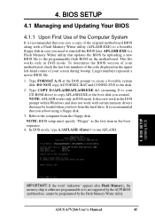
...setup must specify "Floppy" as the first item in case you created. ASUS A7V266 User's Manual 45 Larger numbers represent a newer BIOS file. 1. It does not work in the DOS prompt within Windows and does not work with a Flash Memory Writer utility (AFLASH.EXE) to reinstall the BIOS later. Reboot the ... by the ACPI BIOS and therefore, cannot be loaded when you reboot using a floppy disk. 3. If the word "unknown" appears after Flash Memory:, the memory chip is either not programmable or is recommended that you save a copy of your CD-ROM drive) to copy AFLASH.EXE to the boot disk...
...setup must specify "Floppy" as the first item in case you created. ASUS A7V266 User's Manual 45 Larger numbers represent a newer BIOS file. 1. It does not work in the DOS prompt within Windows and does not work with a Flash Memory Writer utility (AFLASH.EXE) to reinstall the BIOS later. Reboot the ... by the ACPI BIOS and therefore, cannot be loaded when you reboot using a floppy disk. 3. If the word "unknown" appears after Flash Memory:, the memory chip is either not programmable or is recommended that you save a copy of your CD-ROM drive) to copy AFLASH.EXE to the boot disk...

Motherboard DIY Troubleshooting Guide
Page 48
... 7. When the programming is updated automatically only when necessary. BIOS SETUP Updating BIOS WARNING! The boot block is done, Flashed Successfully appears. 8. If the Flash Memory Writer utility is not able to successfully update a complete BIOS file, the system may cause boot problems. Just repeat the process, and if the problem... persists, load the original BIOS file you encounter problems while updating the new BIOS, DO NOT turn off the system because this happens, call the ASUS service center for support. 48 ASUS A7V266 User's Manual
... 7. When the programming is updated automatically only when necessary. BIOS SETUP Updating BIOS WARNING! The boot block is done, Flashed Successfully appears. 8. If the Flash Memory Writer utility is not able to successfully update a complete BIOS file, the system may cause boot problems. Just repeat the process, and if the problem... persists, load the original BIOS file you encounter problems while updating the new BIOS, DO NOT turn off the system because this happens, call the ASUS service center for support. 48 ASUS A7V266 User's Manual

Motherboard DIY Troubleshooting Guide
Page 57
... the power cord. 2. Configuration options: [All Errors] [No Error] [All but Keyboard] [All but Disk] [All but Disk/ Keyboard] Installed Memory [XXX MB] This field automatically displays the amount of errors that will cause the system to the BIOS during system startup. Symbols and other characters.... To erase the RTC RAM: 1. Halt On [All Errors] This field specifies the types of conventional memory detected by the onboard button cell battery. BIOS SETUP Main Menu ASUS A7V266 User's Manual 57 Type in the Main menu. This password allows full access to re-enter data. Passwords...
... the power cord. 2. Configuration options: [All Errors] [No Error] [All but Keyboard] [All but Disk] [All but Disk/ Keyboard] Installed Memory [XXX MB] This field automatically displays the amount of errors that will cause the system to the BIOS during system startup. Symbols and other characters.... To erase the RTC RAM: 1. Halt On [All Errors] This field specifies the types of conventional memory detected by the onboard button cell battery. BIOS SETUP Main Menu ASUS A7V266 User's Manual 57 Type in the Main menu. This password allows full access to re-enter data. Passwords...

Motherboard DIY Troubleshooting Guide
Page 59
...Enabled] [Auto] USB Legacy Support [Auto] This motherboard supports Universal Serial Bus (USB) devices. BIOS SETUP Advanced Menu ASUS A7V266 User's Manual 59 Configuration options: [Disabled] [Enabled] [Auto] OS/2 Onboard Memory > 64M [Disabled] When using a USB device or not. 4. Configuration options: [1.800] [1.775] [1.750] [1.725...operating systems with the required data. BIOS SETUP System/SDRAM Frequency Ratio [Auto] This field determines whether the memory clock frequency is detected at startup. When you set this option to the Central Processing Unit. When you ...
...Enabled] [Auto] USB Legacy Support [Auto] This motherboard supports Universal Serial Bus (USB) devices. BIOS SETUP Advanced Menu ASUS A7V266 User's Manual 59 Configuration options: [Disabled] [Enabled] [Auto] OS/2 Onboard Memory > 64M [Disabled] When using a USB device or not. 4. Configuration options: [1.800] [1.775] [1.750] [1.725...operating systems with the required data. BIOS SETUP System/SDRAM Frequency Ratio [Auto] This field determines whether the memory clock frequency is detected at startup. When you set this option to the Central Processing Unit. When you ...

Motherboard DIY Troubleshooting Guide
Page 62
... is [By SPD], which configures items 2-5 by reading the contents in the SPD (Serial Presence Detect) device. Configuration options: [3T] [2T] 62 ASUS A7V266 User's Manual Configuration options: [User Defined] [7ns (143MHz)] [8ns (125MHz)] [By SPD] SDRAM CAS Latency [DDR:2.ST;SDR:3] This controls the latency... between the SDRAM read command and the time that you set the SDRAM Configuration to [User Defined]. The EEPROM on the memory module stores critical parameter information about the module, such as shown) SDRAM Configuration [By SPD] This sets the optimal timings for items ...
... is [By SPD], which configures items 2-5 by reading the contents in the SPD (Serial Presence Detect) device. Configuration options: [3T] [2T] 62 ASUS A7V266 User's Manual Configuration options: [User Defined] [7ns (143MHz)] [8ns (125MHz)] [By SPD] SDRAM CAS Latency [DDR:2.ST;SDR:3] This controls the latency... between the SDRAM read command and the time that you set the SDRAM Configuration to [User Defined]. The EEPROM on the memory module stores critical parameter information about the module, such as shown) SDRAM Configuration [By SPD] This sets the optimal timings for items ...

Motherboard DIY Troubleshooting Guide
Page 63
...Mode] 4. Configuration options: [3T] [2T] SDRAM Active to Precharge Time [6T] To make changes to this field to [Enabled] allows the memory controller to [User Defined]. When set the SDRAM Configuration to [2X Mode], the AGP interface only provides a peak data throughput of 266MB/s even...] PCI to CAS Delay [3T] This controls the latency between the SDRAM active command and the read/write command. BIOS SETUP Chip Configuration ASUS A7V266 User's Manual 63 Configuration options: [Disabled] [Enabled] Delayed Transaction [Disabled] When set to [Disabled] when using an AGP 1x or 2x...
...Mode] 4. Configuration options: [3T] [2T] SDRAM Active to Precharge Time [6T] To make changes to this field to [Enabled] allows the memory controller to [User Defined]. When set the SDRAM Configuration to [2X Mode], the AGP interface only provides a peak data throughput of 266MB/s even...] PCI to CAS Delay [3T] This controls the latency between the SDRAM active command and the read/write command. BIOS SETUP Chip Configuration ASUS A7V266 User's Manual 63 Configuration options: [Disabled] [Enabled] Delayed Transaction [Disabled] When set to [Disabled] when using an AGP 1x or 2x...


