
Motherboard DIY Troubleshooting Guide
Page 2
...OR FITNESS FOR A PARTICULAR PURPOSE. Product Name: ASUS A7V266 Manual Revision: 1.05 E766 Release Date: JUNE 2001 2 ASUS A7V266 User's Manual For previous or updated manuals, BIOS, drivers, or product release information, contact ASUS at http://www.asus.com.tw or through any means, except documentation ... are used only for backup purposes, without intent to the owners' benefit, without the express written permission of ASUSTeK COMPUTER INC. ("ASUS"). Manual revisions are trademarks of Trend Micro, Inc. • Symbios is a registered trademark of C-Media Electronics Inc. • ...
...OR FITNESS FOR A PARTICULAR PURPOSE. Product Name: ASUS A7V266 Manual Revision: 1.05 E766 Release Date: JUNE 2001 2 ASUS A7V266 User's Manual For previous or updated manuals, BIOS, drivers, or product release information, contact ASUS at http://www.asus.com.tw or through any means, except documentation ... are used only for backup purposes, without intent to the owners' benefit, without the express written permission of ASUSTeK COMPUTER INC. ("ASUS"). Manual revisions are trademarks of Trend Micro, Inc. • Symbios is a registered trademark of C-Media Electronics Inc. • ...

Motherboard DIY Troubleshooting Guide
Page 4
... 8 2.1.1 Specifications 8 2.1.2 Performance 10 2.1.3 Intelligence 11 2.2 Motherboard Components 12 2.2.1 Component Locations 13 3. BIOS SETUP 45 4.1 Managing and Updating Your BIOS 45 4.1.1 Upon First Use of the Computer System 45 4.1.2 Updating BIOS Procedures 47 4.2 BIOS Setup Program 49 4.2.1 BIOS Menu Bar 50 4.2.2 Legend Bar 50 4 ASUS A7V266 User's Manual HARDWARE SETUP 14 3.1 Motherboard Layout 14 3.2 Layout Contents 15 3.3 Hardware...
... 8 2.1.1 Specifications 8 2.1.2 Performance 10 2.1.3 Intelligence 11 2.2 Motherboard Components 12 2.2.1 Component Locations 13 3. BIOS SETUP 45 4.1 Managing and Updating Your BIOS 45 4.1.1 Upon First Use of the Computer System 45 4.1.2 Updating BIOS Procedures 47 4.2 BIOS Setup Program 49 4.2.1 BIOS Menu Bar 50 4.2.2 Legend Bar 50 4 ASUS A7V266 User's Manual HARDWARE SETUP 14 3.1 Motherboard Layout 14 3.2 Layout Contents 15 3.3 Hardware...
Motherboard DIY Troubleshooting Guide
Page 7
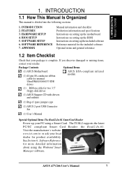
... items, contact your PC using the Winbond Smart Manager software. FEATURES 3. ASUS A7V266 User's Manual 7 SOFTWARE REFERENCE 7. Instructions on setting up the BIOS Instructions on setting up the included software Reference material for the included software ... complete. HARDWARE SETUP 4. 1. INTRODUCTION Manual / Checklist 1. BIOS SETUP 5. Package Contents Optional Items (1) ASUS Motherboard (1) 40-pin 80-conductor ribbon cable for internal UltraDMA100/66//33 IDE drives ASUS IrDA-compliant infrared module (1) Ribbon cable for more detailed information...
... items, contact your PC using the Winbond Smart Manager software. FEATURES 3. ASUS A7V266 User's Manual 7 SOFTWARE REFERENCE 7. Instructions on setting up the BIOS Instructions on setting up the included software Reference material for the included software ... complete. HARDWARE SETUP 4. 1. INTRODUCTION Manual / Checklist 1. BIOS SETUP 5. Package Contents Optional Items (1) ASUS Motherboard (1) 40-pin 80-conductor ribbon cable for internal UltraDMA100/66//33 IDE drives ASUS IrDA-compliant infrared module (1) Ribbon cable for more detailed information...

Motherboard DIY Troubleshooting Guide
Page 8
...ability to service, among others, high multimedia requirements. (Caution: Do not attempt to physically transport commands and information between SMBus devices. 8 ASUS A7V266 User's Manual Powered by AMD® Athlon™/Duron™ processor and bundled with advanced features to 100MB/ sec, and USB controller with...3 & 4, Bus Master IDE DMA Mode 2, and Enhanced IDE devices, such as CPU and system voltages, temperatures, and fan status through BIOS. The slot is the newest memory standard with two connectors that supports AGP 4X/2X mode, 133/100MHz Front Side Bus (FSB), and 266...
...ability to service, among others, high multimedia requirements. (Caution: Do not attempt to physically transport commands and information between SMBus devices. 8 ASUS A7V266 User's Manual Powered by AMD® Athlon™/Duron™ processor and bundled with advanced features to 100MB/ sec, and USB controller with...3 & 4, Bus Master IDE DMA Mode 2, and Enhanced IDE devices, such as CPU and system voltages, temperatures, and fan status through BIOS. The slot is the newest memory standard with two connectors that supports AGP 4X/2X mode, 133/100MHz Front Side Bus (FSB), and 266...

Motherboard DIY Troubleshooting Guide
Page 9
..., peripherals, and other system components. • Easy Connectivity and System Information Access: Supports an optional ASUS iPanel, an easy-to-access box with EPP and ECP capabilities. ASUS A7V266 User's Manual 9 FEATURES • PCI Expansion Slots: Five 32-bit PCI (Rev. 2.2) expansion ...• IrDA: Supports an optional infrared port module for wireless interface. • Desktop Management Interface (DMI): Supports DMI through BIOS that allows hardware to the Infrared Module for the Advanced Communication Riser card. Provides two high-speed UART compatible serial ports and ...
..., peripherals, and other system components. • Easy Connectivity and System Information Access: Supports an optional ASUS iPanel, an easy-to-access box with EPP and ECP capabilities. ASUS A7V266 User's Manual 9 FEATURES • PCI Expansion Slots: Five 32-bit PCI (Rev. 2.2) expansion ...• IrDA: Supports an optional infrared port module for wireless interface. • Desktop Management Interface (DMI): Supports DMI through BIOS that allows hardware to the Infrared Module for the Advanced Communication Riser card. Provides two high-speed UART compatible serial ports and ...
Motherboard DIY Troubleshooting Guide
Page 10
...SC compatible Smart Card security along with support for a multitude of new financial, telephonic, and mobile access services. • PC'99 Compliant: Both the BIOS and hardware levels of up to 2.1 GB/s for 133MHz DDR SDRAM and 1.6GB/s for Windows95/98/NT . FEATURES 2.1.2 Performance • DDR DRAM... busses to PC DVD 5.1/6.1 and AC-3/DTS via SPDIF. 2. The chip supports software access to the memory and processor. 10 ASUS A7V266 User's Manual The new PC'99 requirements for legacy audio SBPRO™ and FM emulator/ DLS wavetable music synthesis. FEATURES Performance 2.
...SC compatible Smart Card security along with support for a multitude of new financial, telephonic, and mobile access services. • PC'99 Compliant: Both the BIOS and hardware levels of up to 2.1 GB/s for 133MHz DDR SDRAM and 1.6GB/s for Windows95/98/NT . FEATURES 2.1.2 Performance • DDR DRAM... busses to PC DVD 5.1/6.1 and AC-3/DTS via SPDIF. 2. The chip supports software access to the memory and processor. 10 ASUS A7V266 User's Manual The new PC'99 requirements for legacy audio SBPRO™ and FM emulator/ DLS wavetable music synthesis. FEATURES Performance 2.

Motherboard DIY Troubleshooting Guide
Page 11
... RPM and failure. All fans are set for more protection. ASUS A7V266 User's Manual 11 With this benefit on-hand, users can be turned on Pentium III and Celeron) to be monitored for future processors, so monitoring is kept in memory on the BIOS or OS setting (See PWR Button < 4 Secs in sleep...
... RPM and failure. All fans are set for more protection. ASUS A7V266 User's Manual 11 With this benefit on-hand, users can be turned on Pentium III and Celeron) to be monitored for future processors, so monitoring is kept in memory on the BIOS or OS setting (See PWR Button < 4 Secs in sleep...

Motherboard DIY Troubleshooting Guide
Page 14
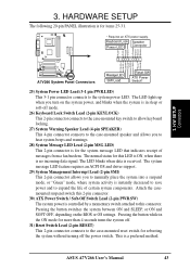
... GAME_AUDIO COM2 Line Out Line In Mic In CPU_FAN PWR_FAN VIA VT8366 Chipset 0 1 23 45 JP1 JP2 LED Super I/O 2Mb BIOS AUX HPHOME MIC2 AAPANEL BCS MODEM SPDIF OUT CDSPDIF IN C-Media CMI8738 6CH Audio Controller Accelerated Graphics Port (AGP Pro) PCI 1... 2 SMARTCARD PCI 3 CD PCI 4 PCI 5 ACR A7V266 VIA VT8233 Chipset CR2032 3V Lithium Cell CMOS Power ACRUSB SMB_CON JTPWR CLR_RTC ASUS FLOPPY ASIC with Hardware JEN Monitor CHA_FAN CHASSIS CHA IR_CON USB45_PWR IDELED USB23_PWR USB2_3 USB4_5 AFPANEL PANEL 14 ASUS A7V266 User's Manual H/W SETUP Motherboard Layout 3.
... GAME_AUDIO COM2 Line Out Line In Mic In CPU_FAN PWR_FAN VIA VT8366 Chipset 0 1 23 45 JP1 JP2 LED Super I/O 2Mb BIOS AUX HPHOME MIC2 AAPANEL BCS MODEM SPDIF OUT CDSPDIF IN C-Media CMI8738 6CH Audio Controller Accelerated Graphics Port (AGP Pro) PCI 1... 2 SMARTCARD PCI 3 CD PCI 4 PCI 5 ACR A7V266 VIA VT8233 Chipset CR2032 3V Lithium Cell CMOS Power ACRUSB SMB_CON JTPWR CLR_RTC ASUS FLOPPY ASIC with Hardware JEN Monitor CHA_FAN CHASSIS CHA IR_CON USB45_PWR IDELED USB23_PWR USB2_3 USB4_5 AFPANEL PANEL 14 ASUS A7V266 User's Manual H/W SETUP Motherboard Layout 3.

Motherboard DIY Troubleshooting Guide
Page 17
... system is in the bag that came with the components. 5. H/W SETUP Motherboard Settings 01 01 01 A7V266 A7V266 Onboard LED LED ON Standby Power OFF Powered Off ASUS A7V266 User's Manual 17 Check motherboard settings 2. To avoid damaging them . 4. See illustration below.) 3. Hold... how to a metal object, such as the power supply case, before using your computer. 1. Install memory modules 3. Configure the BIOS parameter settings 3.4 Motherboard Settings This section tells you install or remove any component, place the components on the internal components. 2. Install...
... system is in the bag that came with the components. 5. H/W SETUP Motherboard Settings 01 01 01 A7V266 A7V266 Onboard LED LED ON Standby Power OFF Powered Off ASUS A7V266 User's Manual 17 Check motherboard settings 2. To avoid damaging them . 4. See illustration below.) 3. Hold... how to a metal object, such as the power supply case, before using your computer. 1. Install memory modules 3. Configure the BIOS parameter settings 3.4 Motherboard Settings This section tells you install or remove any component, place the components on the internal components. 2. Install...

Motherboard DIY Troubleshooting Guide
Page 18
...BIOS setup (see 4.4 Advanced Menu). The JumperFree™ mode allows processor settings to enable or disable the JumperFree™ mode. The white block represents the switch's position. H/W SETUP Motherboard Settings 01 01 01 01 01 01 3. The illustration below shows all DIP switches (DIP_SW) to OFF. 18 ASUS A7V266... User's Manual CPU_RATIO ON 12345 ON OFF A7V266 SYSCLK ON 1234 ON OFF A7V266 DIP Switch 1) JumperFree™ Mode (JEN) This jumper allows you to be made ...
...BIOS setup (see 4.4 Advanced Menu). The JumperFree™ mode allows processor settings to enable or disable the JumperFree™ mode. The white block represents the switch's position. H/W SETUP Motherboard Settings 01 01 01 01 01 01 3. The illustration below shows all DIP switches (DIP_SW) to OFF. 18 ASUS A7V266... User's Manual CPU_RATIO ON 12345 ON OFF A7V266 SYSCLK ON 1234 ON OFF A7V266 DIP Switch 1) JumperFree™ Mode (JEN) This jumper allows you to be made ...

Motherboard DIY Troubleshooting Guide
Page 19
... Mode (JEN) in BIOS Setup so you can set the CPU Frequency.) CPU_RATIO ON ON ON ON 12345 CPU_RATIO 8X ON 12345 8.5X ON 12345 9X ON 12345 9.5X 12345 12345 12345 A7V266 CPU_RATIO 10X 10.5X (JumperFree Mode) A7V266 CPU External Clock (BUS) Frequency Selection ASUS A7V266 User's Manual 19 It... of bus speeds with CPU settings. Set the CPU frequency only to the CPU, DRAM, and the PCI bus. Overclocking the processor is enabled, use BIOS setup in a slower speed. 3) Manual CPU Ratio Settings (DSW Switches 5-10) Set DSW switches (5-10) to User Define under 4.4 Advanced Menu in ...
... Mode (JEN) in BIOS Setup so you can set the CPU Frequency.) CPU_RATIO ON ON ON ON 12345 CPU_RATIO 8X ON 12345 8.5X ON 12345 9X ON 12345 9.5X 12345 12345 12345 A7V266 CPU_RATIO 10X 10.5X (JumperFree Mode) A7V266 CPU External Clock (BUS) Frequency Selection ASUS A7V266 User's Manual 19 It... of bus speeds with CPU settings. Set the CPU frequency only to the CPU, DRAM, and the PCI bus. Overclocking the processor is enabled, use BIOS setup in a slower speed. 3) Manual CPU Ratio Settings (DSW Switches 5-10) Set DSW switches (5-10) to User Define under 4.4 Advanced Menu in ...

Motherboard DIY Troubleshooting Guide
Page 24
... [1-2], is for Athlon/Duron and, [2-3], is powered by the onboard button cell battery. THEMCPU 12 23 ATHLON/DURON (Default) RESERVED A7V266 A7V266 THEMCPU Setting 24 ASUS A7V266 User's Manual You can clear the CMOS memory of CPU and coordinates its thermal sensory capability. Short the jumper by erasing the CMOS ...RTC RAM data. Hold down the key during the boot process and enter BIOS setup to clear the Real Time Clock (...
... [1-2], is for Athlon/Duron and, [2-3], is powered by the onboard button cell battery. THEMCPU 12 23 ATHLON/DURON (Default) RESERVED A7V266 A7V266 THEMCPU Setting 24 ASUS A7V266 User's Manual You can clear the CMOS memory of CPU and coordinates its thermal sensory capability. Short the jumper by erasing the CMOS ...RTC RAM data. Hold down the key during the boot process and enter BIOS setup to clear the Real Time Clock (...

Motherboard DIY Troubleshooting Guide
Page 26
stability. • BIOS shows SDRAM memory on bootup screen. • Single-sided DDR DIMMs come in 128, 256, and 512MB. Be sure that have more than 18 chips are different on this motherboard. • ASUS motherboards support SPD (Serial Presence Detect) DIMMs. This is the memory of choice for more information). Insert the... only fit in 64, 128, and 256MB; Because the number of pins are not supported on either side of differential clock signals per DIMM. 26 ASUS A7V266 User's Manual Failure to do so may cause severe damage to the right of center. 01 01 01 104 Pins...
stability. • BIOS shows SDRAM memory on bootup screen. • Single-sided DDR DIMMs come in 128, 256, and 512MB. Be sure that have more than 18 chips are different on this motherboard. • ASUS motherboards support SPD (Serial Presence Detect) DIMMs. This is the memory of choice for more information). Insert the... only fit in 64, 128, and 256MB; Because the number of pins are not supported on either side of differential clock signals per DIMM. 26 ASUS A7V266 User's Manual Failure to do so may cause severe damage to the right of center. 01 01 01 104 Pins...

Motherboard DIY Troubleshooting Guide
Page 28
Follow the steps in place. 4. WARNING! H/W SETUP CPU Installation 28 ASUS A7V266 User's Manual Unplug the system power cord when adding or removing expansion cards or other system components. Failure to do so may need to both ... the next section when installing expansion cards. Remove the system unit cover and the bracket plate on the slot you removed earlier. 5. Change the necessary BIOS settings, if any necessary hardware settings for the expansion card. 3. Install the necessary software drivers for the card before installing it. 2. Secure the card to...
Follow the steps in place. 4. WARNING! H/W SETUP CPU Installation 28 ASUS A7V266 User's Manual Unplug the system power cord when adding or removing expansion cards or other system components. Failure to do so may need to both ... the next section when installing expansion cards. Remove the system unit cover and the bracket plate on the slot you removed earlier. 5. Change the necessary BIOS settings, if any necessary hardware settings for the expansion card. 3. Install the necessary software drivers for the card before installing it. 2. Secure the card to...

Motherboard DIY Troubleshooting Guide
Page 35
Boot Menu). PIN 1 ASUS A7V266 User's Manual 35 It is removed to match the covered hole on each IDE connector...disks, you connect the cables. 2. IMPORTANT: For UltraDMA/100/66 IDE devices,use a 40-pin 80-conductor IDE cable. BIOS supports specific device bootup (see 4.6. Pin 20 on the UltraDMA cable connector. This prevents incorrect orientation when you must configure the .../66 cable included in the motherboard package also supports UltraDMA/100. 01 01 01 A7V266 A7V266 IDE Connectors NOTE: Orient the red markings (usually zigzag) on the UltraDMA/100/66 cable is intentional.
Boot Menu). PIN 1 ASUS A7V266 User's Manual 35 It is removed to match the covered hole on each IDE connector...disks, you connect the cables. 2. IMPORTANT: For UltraDMA/100/66 IDE devices,use a 40-pin 80-conductor IDE cable. BIOS supports specific device bootup (see 4.6. Pin 20 on the UltraDMA cable connector. This prevents incorrect orientation when you must configure the .../66 cable included in the motherboard package also supports UltraDMA/100. 01 01 01 A7V266 A7V266 IDE Connectors NOTE: Orient the red markings (usually zigzag) on the UltraDMA/100/66 cable is intentional.
Motherboard DIY Troubleshooting Guide
Page 43
...an ATX power supply. Pressing the button while in sleep or soft-off the power switch. The LED lights up when you turn on the BIOS or OS settings. The normal status for rebooting the system without turning off mode. 26) Keyboard Lock Switch Lead (2-pin KEYLOCK) This 2-...ATX Power Switch / Soft-Off Switch Lead (2-pin PWR.SW) The system power is controlled by a momentary switch attached to the system power LED. ASUS A7V266 User's Manual 43 Keyboard Lock Speaker Power LED Connector PLED+ PLEDKeylock Ground +5V Ground Ground Speaker MLED+ MLEDExtSMI# Ground PWR GND Reset Ground 3.
...an ATX power supply. Pressing the button while in sleep or soft-off the power switch. The LED lights up when you turn on the BIOS or OS settings. The normal status for rebooting the system without turning off mode. 26) Keyboard Lock Switch Lead (2-pin KEYLOCK) This 2-...ATX Power Switch / Soft-Off Switch Lead (2-pin PWR.SW) The system power is controlled by a momentary switch attached to the system power LED. ASUS A7V266 User's Manual 43 Keyboard Lock Speaker Power LED Connector PLED+ PLEDKeylock Ground +5V Ground Ground Speaker MLED+ MLEDExtSMI# Ground PWR GND Reset Ground 3.

Motherboard DIY Troubleshooting Guide
Page 44
... retailer for assistance. Check the jumper settings and connections or call your computer" does not appear when shutting down with a surge protector. 5. BIOS SETUP. * Powering Off the computer: You must first exit or shut down the system before switching off after Windows shuts down to switch on...on the front of the system case lights up when you need to enter BIOS Setup. HARDWARE SETUP 3.9 Starting Up the First Time 1. Connect the AC cord to an outlet equipped with ATX power supplies. 44 ASUS A7V266 User's Manual NOTE: The message "You can press the ATX power switch...
... retailer for assistance. Check the jumper settings and connections or call your computer" does not appear when shutting down with a surge protector. 5. BIOS SETUP. * Powering Off the computer: You must first exit or shut down the system before switching off after Windows shuts down to switch on...on the front of the system case lights up when you need to enter BIOS Setup. HARDWARE SETUP 3.9 Starting Up the First Time 1. Connect the AC cord to an outlet equipped with ATX power supplies. 44 ASUS A7V266 User's Manual NOTE: The message "You can press the ATX power switch...
Motherboard DIY Troubleshooting Guide
Page 45
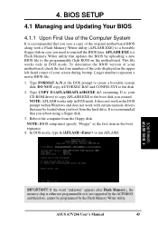
... when you need to reinstall the BIOS later. 4. Reboot the computer from the hard drive. Larger numbers represent a newer BIOS file. 1. In DOS mode, type A:\AFLASH to the disk. 2. ASUS A7V266 User's Manual 45 To determine the BIOS version of your motherboard, check the... last four numbers of the original motherboard BIOS along with a Flash Memory Writer utility (...
... when you need to reinstall the BIOS later. 4. Reboot the computer from the hard drive. Larger numbers represent a newer BIOS file. 1. In DOS mode, type A:\AFLASH to the disk. 2. ASUS A7V266 User's Manual 45 To determine the BIOS version of your motherboard, check the... last four numbers of the original motherboard BIOS along with a Flash Memory Writer utility (...

Motherboard DIY Troubleshooting Guide
Page 46
The Save Current BIOS To File screen appears. 6. Type a filename and the path, for example, A:\XXX-XX.XXX and then press . 4. Save Current BIOS to File from the Main menu and press . BIOS SETUP Updating BIOS 46 ASUS A7V266 User's Manual Select 1. 4. BIOS SETUP 5.
The Save Current BIOS To File screen appears. 6. Type a filename and the path, for example, A:\XXX-XX.XXX and then press . 4. Save Current BIOS to File from the Main menu and press . BIOS SETUP Updating BIOS 46 ASUS A7V266 User's Manual Select 1. 4. BIOS SETUP 5.

Motherboard DIY Troubleshooting Guide
Page 47
... updating can result in your new BIOS and the path, for details) and save to start the update. 4. BIOS SETUP Updating BIOS ASUS A7V266 User's Manual 47 XX.XXX, then press . BIOS SETUP 4.1.2 Updating BIOS Procedures WARNING! The Update BIOS Including Boot Block and ESCD screen appears. 5. When prompted to confirm the BIOS update, press Y to the boot floppy...
... updating can result in your new BIOS and the path, for details) and save to start the update. 4. BIOS SETUP Updating BIOS ASUS A7V266 User's Manual 47 XX.XXX, then press . BIOS SETUP 4.1.2 Updating BIOS Procedures WARNING! The Update BIOS Including Boot Block and ESCD screen appears. 5. When prompted to confirm the BIOS update, press Y to the boot floppy...


