
Motherboard DIY Troubleshooting Guide
Page 2
...Reserved. or (2) the serial number of the product is a registered trademark of Symbios Logic Corporation. Product Name: ASUS A7V266 Manual Revision: 1.05 E766 Release Date: JUNE 2001 2 ASUS A7V266 User's Manual USER'S NOTICE No part of this manual may or may be reproduced, transmitted, transcribed, stored ...on the following page. Copyright © 2001 ASUSTeK COMPUTER INC. For previous or updated manuals, BIOS, drivers, or product release information, contact ASUS at http://www.asus.com.tw or through any of the manual revision number. Manual revisions are represented by the ...
...Reserved. or (2) the serial number of the product is a registered trademark of Symbios Logic Corporation. Product Name: ASUS A7V266 Manual Revision: 1.05 E766 Release Date: JUNE 2001 2 ASUS A7V266 User's Manual USER'S NOTICE No part of this manual may or may be reproduced, transmitted, transcribed, stored ...on the following page. Copyright © 2001 ASUSTeK COMPUTER INC. For previous or updated manuals, BIOS, drivers, or product release information, contact ASUS at http://www.asus.com.tw or through any of the manual revision number. Manual revisions are represented by the ...

Motherboard DIY Troubleshooting Guide
Page 4
... 31 3.8.1 External Connectors 31 3.9 Starting Up the First Time 44 4. BIOS SETUP 45 4.1 Managing and Updating Your BIOS 45 4.1.1 Upon First Use of the Computer System 45 4.1.2 Updating BIOS Procedures 47 4.2 BIOS Setup Program 49 4.2.1 BIOS Menu Bar 50 4.2.2 Legend Bar 50 4 ASUS A7V266 User's Manual FEATURES 8 2.1 ASUS A7V266 Motherboard 8 2.1.1 Specifications 8 2.1.2 Performance 10 2.1.3 Intelligence 11 2.2 Motherboard Components 12 2.2.1 Component...
... 31 3.8.1 External Connectors 31 3.9 Starting Up the First Time 44 4. BIOS SETUP 45 4.1 Managing and Updating Your BIOS 45 4.1.1 Upon First Use of the Computer System 45 4.1.2 Updating BIOS Procedures 47 4.2 BIOS Setup Program 49 4.2.1 BIOS Menu Bar 50 4.2.2 Legend Bar 50 4 ASUS A7V266 User's Manual FEATURES 8 2.1 ASUS A7V266 Motherboard 8 2.1.1 Specifications 8 2.1.2 Performance 10 2.1.3 Intelligence 11 2.2 Motherboard Components 12 2.2.1 Component...
Motherboard DIY Troubleshooting Guide
Page 7
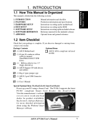
... divided into the following sections: 1. INTRODUCTION 2. FEATURES 3. Instructions on setting up the BIOS Instructions on setting up the motherboard. Package Contents Optional Items (1) ASUS Motherboard (1) 40-pin 80-conductor ribbon cable for internal UltraDMA100/66//33 IDE drives ASUS IrDA-compliant infrared module (1) Ribbon cable for product availability. INTRODUCTION Manual / Checklist 1. ... and specifications Instructions on setting up your retailer. The TUSL2 supports the latest PC/SC compliant Smart Card Reader: the Read2-In-01. ASUS A7V266 User's Manual 7
... divided into the following sections: 1. INTRODUCTION 2. FEATURES 3. Instructions on setting up the BIOS Instructions on setting up the motherboard. Package Contents Optional Items (1) ASUS Motherboard (1) 40-pin 80-conductor ribbon cable for internal UltraDMA100/66//33 IDE drives ASUS IrDA-compliant infrared module (1) Ribbon cable for product availability. INTRODUCTION Manual / Checklist 1. ... and specifications Instructions on setting up your retailer. The TUSL2 supports the latest PC/SC compliant Smart Card Reader: the Read2-In-01. ASUS A7V266 User's Manual 7

Motherboard DIY Troubleshooting Guide
Page 8
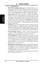
... devices, such as CPU and system voltages, temperatures, and fan status through BIOS. Powered by AMD® Athlon™/Duron™ processor and bundled with advanced features to provide superlative performance, the A7V266 efficiently complies with today's demand for six USB ports. • PC2100 /...• JumperFree™ Mode: Allows processor settings and easy overclocking of frequency and Vcore voltage through the onboard hardware ASUS ASIC and the bundled ASUS PC Probe. • SMBus: Features the System Management Bus interface used to use DIP switches come with an Accelerated ...
... devices, such as CPU and system voltages, temperatures, and fan status through BIOS. Powered by AMD® Athlon™/Duron™ processor and bundled with advanced features to provide superlative performance, the A7V266 efficiently complies with today's demand for six USB ports. • PC2100 /...• JumperFree™ Mode: Allows processor settings and easy overclocking of frequency and Vcore voltage through the onboard hardware ASUS ASIC and the bundled ASUS PC Probe. • SMBus: Features the System Management Bus interface used to use DIP switches come with an Accelerated ...

Motherboard DIY Troubleshooting Guide
Page 9
...Communication Riser (ACR): Features an ACR slot for the Advanced Communication Riser card. The AFPANEL connector on the motherboard. 2. ASUS A7V266 User's Manual 9 The ACR specification supports modem, audio and LAN technologies. The ACR is any standby power on the motherboard accommodates the...complete support for wireless connections. The Super I/O controller also supports a floppy disk drive, PS/2 keyboard, and PS/2 mouse. • Smart BIOS: 2Mb firmware provides Vcore and CPU/DDR SDRAM frequency adjustments, boot block write protection, and HD/SCSI/MO/ZIP/CD/Floppy boot selection. ...
...Communication Riser (ACR): Features an ACR slot for the Advanced Communication Riser card. The AFPANEL connector on the motherboard. 2. ASUS A7V266 User's Manual 9 The ACR specification supports modem, audio and LAN technologies. The ACR is any standby power on the motherboard accommodates the...complete support for wireless connections. The Super I/O controller also supports a floppy disk drive, PS/2 keyboard, and PS/2 mouse. • Smart BIOS: 2Mb firmware provides Vcore and CPU/DDR SDRAM frequency adjustments, boot block write protection, and HD/SCSI/MO/ZIP/CD/Floppy boot selection. ...
Motherboard DIY Troubleshooting Guide
Page 10
... Features for a multitude of new financial, telephonic, and mobile access services. • PC'99 Compliant: Both the BIOS and hardware levels of ASUS smart series motherboards are based on the following high-level goals: Support for Plugn-Play compatibility and power management for configuring...conductor cable). • Concurrent PCI: Concurrent PCI allows multiple PCI transfers from PCI master busses to the memory and processor. 10 ASUS A7V266 User's Manual The new PC'99 requirements for systems and components are PC'99 compliant. 2. With these features employed in data transfer...
... Features for a multitude of new financial, telephonic, and mobile access services. • PC'99 Compliant: Both the BIOS and hardware levels of ASUS smart series motherboards are based on the following high-level goals: Support for Plugn-Play compatibility and power management for configuring...conductor cable). • Concurrent PCI: Concurrent PCI allows multiple PCI transfers from PCI master busses to the memory and processor. 10 ASUS A7V266 User's Manual The new PC'99 requirements for systems and components are PC'99 compliant. 2. With these features employed in data transfer...

Motherboard DIY Troubleshooting Guide
Page 11
... Detection: Supports chassis-intrusion monitoring through an internal or external modem. 2. ASUS A7V266 User's Manual 11 When the power button is pressed for future processors, so monitoring is kept in memory on the BIOS or OS setting (See PWR Button < 4 Secs in sleep mode. This... seconds when the system is monitored by the ASUS ASIC through the CPU's internal thermal diode (on remotely through the ASUS ASIC. FEATURES 2.1.3 Intelligence • Auto Fan Off: The system fans powers off mode regardless of the BIOS setting. • Fan Status Monitoring and Alarm...
... Detection: Supports chassis-intrusion monitoring through an internal or external modem. 2. ASUS A7V266 User's Manual 11 When the power button is pressed for future processors, so monitoring is kept in memory on the BIOS or OS setting (See PWR Button < 4 Secs in sleep mode. This... seconds when the system is monitored by the ASUS ASIC through the CPU's internal thermal diode (on remotely through the ASUS ASIC. FEATURES 2.1.3 Intelligence • Auto Fan Off: The system fans powers off mode regardless of the BIOS setting. • Fan Status Monitoring and Alarm...

Motherboard DIY Troubleshooting Guide
Page 14
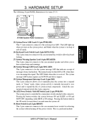
... GAME_AUDIO COM2 Line Out Line In Mic In CPU_FAN PWR_FAN VIA VT8366 Chipset 0 1 23 45 JP1 JP2 LED Super I/O 2Mb BIOS AUX HPHOME MIC2 AAPANEL BCS MODEM SPDIF OUT CDSPDIF IN C-Media CMI8738 6CH Audio Controller Accelerated Graphics Port (AGP Pro) PCI 1...PCI 2 SMARTCARD PCI 3 CD PCI 4 PCI 5 ACR A7V266 VIA VT8233 Chipset CR2032 3V Lithium Cell CMOS Power ACRUSB SMB_CON JTPWR CLR_RTC ASUS FLOPPY ASIC with Hardware JEN Monitor CHA_FAN CHASSIS CHA IR_CON USB45_PWR IDELED USB23_PWR USB2_3 USB4_5 AFPANEL PANEL 14 ASUS A7V266 User's Manual H/W SETUP Motherboard Layout 3.
... GAME_AUDIO COM2 Line Out Line In Mic In CPU_FAN PWR_FAN VIA VT8366 Chipset 0 1 23 45 JP1 JP2 LED Super I/O 2Mb BIOS AUX HPHOME MIC2 AAPANEL BCS MODEM SPDIF OUT CDSPDIF IN C-Media CMI8738 6CH Audio Controller Accelerated Graphics Port (AGP Pro) PCI 1...PCI 2 SMARTCARD PCI 3 CD PCI 4 PCI 5 ACR A7V266 VIA VT8233 Chipset CR2032 3V Lithium Cell CMOS Power ACRUSB SMB_CON JTPWR CLR_RTC ASUS FLOPPY ASIC with Hardware JEN Monitor CHA_FAN CHASSIS CHA IR_CON USB45_PWR IDELED USB23_PWR USB2_3 USB4_5 AFPANEL PANEL 14 ASUS A7V266 User's Manual H/W SETUP Motherboard Layout 3.

Motherboard DIY Troubleshooting Guide
Page 17
Install memory modules 3. Configure the BIOS parameter settings 3.4 Motherboard Settings This section tells you work on them. 4. Unplug the computer when working on a grounded antistatic pad or in the bag that ... or to a metal object, such as the power supply case, before using your computer. 1. H/W SETUP Motherboard Settings 01 01 01 A7V266 A7V266 Onboard LED LED ON Standby Power OFF Powered Off ASUS A7V266 User's Manual 17 Check motherboard settings 2. Connect ribbon cables, panel wires, and power supply cables 6. Before you uninstall any component, ensure...
Install memory modules 3. Configure the BIOS parameter settings 3.4 Motherboard Settings This section tells you work on them. 4. Unplug the computer when working on a grounded antistatic pad or in the bag that ... or to a metal object, such as the power supply case, before using your computer. 1. H/W SETUP Motherboard Settings 01 01 01 A7V266 A7V266 Onboard LED LED ON Standby Power OFF Powered Off ASUS A7V266 User's Manual 17 Check motherboard settings 2. Connect ribbon cables, panel wires, and power supply cables 6. Before you uninstall any component, ensure...

Motherboard DIY Troubleshooting Guide
Page 18
...Switches) The motherboard frequency is adjusted through the BIOS setup (see 4.4 Advanced Menu). The illustration below shows all DIP switches (DIP_SW) to OFF. 18 ASUS A7V266 User's Manual CPU_RATIO ON 12345 ON OFF A7V266 SYSCLK ON 1234 ON OFF A7V266 DIP Switch 1) JumperFree™ Mode (JEN...the switch's position. Setting JEN Enable (JumperFree) [2-3] (default) Disable (Jumper Mode) [1-2] JEN CPU_RATIO A7V266 ON ON 12345 OFF SYSCLK ON 1234 ON OFF 12 23 A7V266 Jumper Mode Setting Jumper Mode Jumper Free (Default) NOTE: In JumperFree™ mode, set all the ...
...Switches) The motherboard frequency is adjusted through the BIOS setup (see 4.4 Advanced Menu). The illustration below shows all DIP switches (DIP_SW) to OFF. 18 ASUS A7V266 User's Manual CPU_RATIO ON 12345 ON OFF A7V266 SYSCLK ON 1234 ON OFF A7V266 DIP Switch 1) JumperFree™ Mode (JEN...the switch's position. Setting JEN Enable (JumperFree) [2-3] (default) Disable (Jumper Mode) [1-2] JEN CPU_RATIO A7V266 ON ON 12345 OFF SYSCLK ON 1234 ON OFF 12 23 A7V266 Jumper Mode Setting Jumper Mode Jumper Free (Default) NOTE: In JumperFree™ mode, set all the ...

Motherboard DIY Troubleshooting Guide
Page 19
...; Mode (JEN) in BIOS Setup so you can set the CPU Frequency.) CPU_RATIO ON ON ON ON 12345 CPU_RATIO 8X ON 12345 8.5X ON 12345 9X ON 12345 9.5X 12345 12345 12345 A7V266 CPU_RATIO 10X 10.5X (JumperFree Mode) A7V266 CPU External Clock (BUS) Frequency Selection ASUS A7V266 User's Manual 19 This ...allows the selection of bus speeds with CPU settings. H/W SETUP Motherboard Settings 01 01 01 01 01 01 SYSCLK ON 1234 ON 1234 ON 1234 ON 1234 CPU 100MHz 133.33MHz 140MHz AGP 60.67MHz 66.67MHz 70MHz (JumperFree Mode) A7V266 PCI 33...
...; Mode (JEN) in BIOS Setup so you can set the CPU Frequency.) CPU_RATIO ON ON ON ON 12345 CPU_RATIO 8X ON 12345 8.5X ON 12345 9X ON 12345 9.5X 12345 12345 12345 A7V266 CPU_RATIO 10X 10.5X (JumperFree Mode) A7V266 CPU External Clock (BUS) Frequency Selection ASUS A7V266 User's Manual 19 This ...allows the selection of bus speeds with CPU settings. H/W SETUP Motherboard Settings 01 01 01 01 01 01 SYSCLK ON 1234 ON 1234 ON 1234 ON 1234 CPU 100MHz 133.33MHz 140MHz AGP 60.67MHz 66.67MHz 70MHz (JumperFree Mode) A7V266 PCI 33...

Motherboard DIY Troubleshooting Guide
Page 24
...RTC RAM: 1. 3. Short the jumper by erasing the CMOS RTC RAM data. Hold down the key during the boot process and enter BIOS setup to clear the Real Time Clock (RTC) RAM in CMOS, that include system setup information such as system passwords, is for Athlon... setup parameters by removing and replacing the jumper cap. 4. The RAM data in CMOS. THEMCPU 12 23 ATHLON/DURON (Default) RESERVED A7V266 A7V266 THEMCPU Setting 24 ASUS A7V266 User's Manual Remove the battery. 3. Plug the power cord and turn ON the computer. 6. The default setting, [1-2], is for Reserve...
...RTC RAM: 1. 3. Short the jumper by erasing the CMOS RTC RAM data. Hold down the key during the boot process and enter BIOS setup to clear the Real Time Clock (RTC) RAM in CMOS, that include system setup information such as system passwords, is for Athlon... setup parameters by removing and replacing the jumper cap. 4. The RAM data in CMOS. THEMCPU 12 23 ATHLON/DURON (Default) RESERVED A7V266 A7V266 THEMCPU Setting 24 ASUS A7V266 User's Manual Remove the battery. 3. Plug the power cord and turn ON the computer. 6. The default setting, [1-2], is for Reserve...

Motherboard DIY Troubleshooting Guide
Page 26
stability. • BIOS shows SDRAM memory on bootup screen. • Single-sided DDR DIMMs come in 64, 128, and 256MB; WARNING! Failure to do so may cause severe damage to the right of center. 01 01 01 104 Pins A7V266 80 Pins A7V266 184-Pin DDR DIMM Sockets This motherboard supports three... come in 128, 256, and 512MB. Because the number of pins are not supported on either side of differential clock signals per DIMM. 26 ASUS A7V266 User's Manual HARDWARE SETUP 3.5.1 General DIMM Notes • DIMMs that you use can handle the specified DDR RAM MHz or else bootup will only...
stability. • BIOS shows SDRAM memory on bootup screen. • Single-sided DDR DIMMs come in 64, 128, and 256MB; WARNING! Failure to do so may cause severe damage to the right of center. 01 01 01 104 Pins A7V266 80 Pins A7V266 184-Pin DDR DIMM Sockets This motherboard supports three... come in 128, 256, and 512MB. Because the number of pins are not supported on either side of differential clock signals per DIMM. 26 ASUS A7V266 User's Manual HARDWARE SETUP 3.5.1 General DIMM Notes • DIMMs that you use can handle the specified DDR RAM MHz or else bootup will only...

Motherboard DIY Troubleshooting Guide
Page 28
... the documentation that comes with the slot and press firmly until the card fits in the next section when installing expansion cards. Change the necessary BIOS settings, if any necessary hardware settings for the card before installing it. 2. HARDWARE SETUP 3.7 Expansion Cards In the future, you may cause severe damage to... on the slot you removed earlier. 5. Secure the card to support these cards. Install the necessary software drivers for later use . H/W SETUP CPU Installation 28 ASUS A7V266 User's Manual
... the documentation that comes with the slot and press firmly until the card fits in the next section when installing expansion cards. Change the necessary BIOS settings, if any necessary hardware settings for the card before installing it. 2. HARDWARE SETUP 3.7 Expansion Cards In the future, you may cause severe damage to... on the slot you removed earlier. 5. Secure the card to support these cards. Install the necessary software drivers for later use . H/W SETUP CPU Installation 28 ASUS A7V266 User's Manual

Motherboard DIY Troubleshooting Guide
Page 35
...: Orient the red markings (usually zigzag) on the IDE ribbon cable to match the covered hole on the UltraDMA cable connector. PIN 1 ASUS A7V266 User's Manual 35 Pin 20 on the UltraDMA/100/66 cable is removed to PIN 1. IMPORTANT: For UltraDMA/100/66 IDE devices,use ... connector, then connect the gray connector to the UltraDMA/100/66 slave device (hard disk drive) and the black connector to the secondary IDE connector. BIOS supports specific device bootup (see 4.6. Boot Menu). NOTES: 1. H/W SETUP Connectors 3. HARDWARE SETUP 10) Primary (Blue) / Secondary IDE Connectors (40-1 pin...
...: Orient the red markings (usually zigzag) on the IDE ribbon cable to match the covered hole on the UltraDMA cable connector. PIN 1 ASUS A7V266 User's Manual 35 Pin 20 on the UltraDMA/100/66 cable is removed to PIN 1. IMPORTANT: For UltraDMA/100/66 IDE devices,use ... connector, then connect the gray connector to the UltraDMA/100/66 slave device (hard disk drive) and the black connector to the secondary IDE connector. BIOS supports specific device bootup (see 4.6. Boot Menu). NOTES: 1. H/W SETUP Connectors 3. HARDWARE SETUP 10) Primary (Blue) / Secondary IDE Connectors (40-1 pin...
Motherboard DIY Troubleshooting Guide
Page 43
.... The normal status for this LED is ON, when there is for the system message LED that indicates receipt of certain system components. ASUS A7V266 User's Manual 43 H/W SETUP Connectors A7V266 A7V266 System Panel Connectors Message LED SMI Lead Reset SW ATX Power Switch* 25) System Power LED Lead (3-1 pin PWR.LED) This 3-1 pin... blinks when data is for items 25-31. 01 01 01 * Requires an ATX power supply. The LED lights up when you turn on the BIOS or OS settings.
.... The normal status for this LED is ON, when there is for the system message LED that indicates receipt of certain system components. ASUS A7V266 User's Manual 43 H/W SETUP Connectors A7V266 A7V266 System Panel Connectors Message LED SMI Lead Reset SW ATX Power Switch* 25) System Power LED Lead (3-1 pin PWR.LED) This 3-1 pin... blinks when data is for items 25-31. 01 01 01 * Requires an ATX power supply. The LED lights up when you turn on the BIOS or OS settings.

Motherboard DIY Troubleshooting Guide
Page 44
...system LED lights up or switch between orange and green after the system LED does. At power on, hold down with ATX power supplies. 44 ASUS A7V266 User's Manual If you turn on the power, the system may light up when you press the ATX power switch. Connect the AC cord ... you need to an outlet equipped with the last device on the front panel of the chassis.) 6. H/W SETUP Connectors 3. Connect the AC cord to enter BIOS Setup. BIOS SETUP. * Powering Off the computer: You must first exit or shut down . 3. Monitor b. System power (For ATX power supplies, you can now safely...
...system LED lights up or switch between orange and green after the system LED does. At power on, hold down with ATX power supplies. 44 ASUS A7V266 User's Manual If you turn on the power, the system may light up when you press the ATX power switch. Connect the AC cord ... you need to an outlet equipped with the last device on the front panel of the chassis.) 6. H/W SETUP Connectors 3. Connect the AC cord to enter BIOS Setup. BIOS SETUP. * Powering Off the computer: You must first exit or shut down . 3. Monitor b. System power (For ATX power supplies, you can now safely...
Motherboard DIY Troubleshooting Guide
Page 45
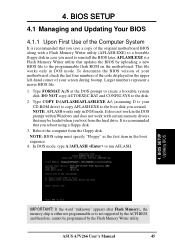
...ROM on the upper left-hand corner of the code displayed on the motherboard. This file works only in DOS mode. Larger numbers represent a newer BIOS file. 1. In DOS mode, type A:\AFLASH to create a bootable system disk. If the word "unknown" appears after Flash Memory:, the memory ...hard drive. NOTE: AFLASH works only in DOS mode. NOTE: BIOS setup must specify "Floppy" as the first item in case you reboot using a floppy disk. 3. 4. DO NOT copy AUTOEXEC.BAT and CONFIG.SYS to reinstall the BIOS later. AFLASH.EXE is your screen during bootup. ASUS A7V266 User's Manual 45
...ROM on the upper left-hand corner of the code displayed on the motherboard. This file works only in DOS mode. Larger numbers represent a newer BIOS file. 1. In DOS mode, type A:\AFLASH to create a bootable system disk. If the word "unknown" appears after Flash Memory:, the memory ...hard drive. NOTE: AFLASH works only in DOS mode. NOTE: BIOS setup must specify "Floppy" as the first item in case you reboot using a floppy disk. 3. 4. DO NOT copy AUTOEXEC.BAT and CONFIG.SYS to reinstall the BIOS later. AFLASH.EXE is your screen during bootup. ASUS A7V266 User's Manual 45

Motherboard DIY Troubleshooting Guide
Page 46
Save Current BIOS to File from the Main menu and press . BIOS SETUP Updating BIOS 46 ASUS A7V266 User's Manual 4. BIOS SETUP 5. The Save Current BIOS To File screen appears. 6. Type a filename and the path, for example, A:\XXX-XX.XXX and then press . 4. Select 1.
Save Current BIOS to File from the Main menu and press . BIOS SETUP Updating BIOS 46 ASUS A7V266 User's Manual 4. BIOS SETUP 5. The Save Current BIOS To File screen appears. 6. Type a filename and the path, for example, A:\XXX-XX.XXX and then press . 4. Select 1.

Motherboard DIY Troubleshooting Guide
Page 47
... Internet (WWW or FTP) (see ASUS CONTACT INFORMATION on page 3 for details) and save to start the update. 4. Type the filename of your motherboard having more problems! 1. BIOS SETUP Updating BIOS ASUS A7V266 User's Manual 47 Update the BIOS only if you have problems with the... motherboard and you created earlier. 2. The Update BIOS Including Boot Block and ESCD screen appears. 5. NOTE: To cancel this...
... Internet (WWW or FTP) (see ASUS CONTACT INFORMATION on page 3 for details) and save to start the update. 4. Type the filename of your motherboard having more problems! 1. BIOS SETUP Updating BIOS ASUS A7V266 User's Manual 47 Update the BIOS only if you have problems with the... motherboard and you created earlier. 2. The Update BIOS Including Boot Block and ESCD screen appears. 5. NOTE: To cancel this...


