

User Guide
Page 2
...://support.asus.com/download or (2) for which is valid to duly provide complete source code as stated in this information. or (2) the serial number of ASUSTeK COMPUTER INC. ("ASUS"). Products and corporate names appearing in this manual, including the products and software described in any form or by any problems in receipt of this product is distributed without the express...
...://support.asus.com/download or (2) for which is valid to duly provide complete source code as stated in this information. or (2) the serial number of ASUSTeK COMPUTER INC. ("ASUS"). Products and corporate names appearing in this manual, including the products and software described in any form or by any problems in receipt of this product is distributed without the express...

User Guide
Page 4
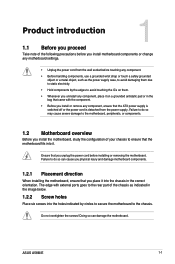
... the voltage of the electrical outlet you are also provided. How this guide This user guide contains the information you need when installing and configuring the motherboard. Detailed descriptions of the motherboard and the new technology it by yourself. Contact a qualified service technician or your retailer. If you detect any area where it , carefully read all cables are correctly connected and the power cables...
... the voltage of the electrical outlet you are also provided. How this guide This user guide contains the information you need when installing and configuring the motherboard. Detailed descriptions of the motherboard and the new technology it by yourself. Contact a qualified service technician or your retailer. If you detect any area where it , carefully read all cables are correctly connected and the power cables...
User Guide
Page 6
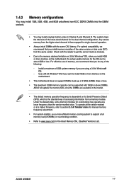
...Supports AMD® Dual Graphics technology * Refer to www.asus.com for the discrete GPUs which support Dual Graphics technology. 1 x PCIe 3.0*/2.0 x16 slot 1 x PCIe 2.0 x1 slot 1 x PCI slot • PCIe 3.0 is damaged or missing, contact your retailer. resolution 1920x1600@60Hz AMD® Dual Graphics technology support* Maximum shared memory of individual CPUs. • The maximum 32GB memory capacity can be supported with max. A58M-E specifications summary CPU Chipset Memory Graphics Expansion slots AMD® FM2+ Socket for AMD® A-Series/Athlon™ Series processors AMD...
...Supports AMD® Dual Graphics technology * Refer to www.asus.com for the discrete GPUs which support Dual Graphics technology. 1 x PCIe 3.0*/2.0 x16 slot 1 x PCIe 2.0 x1 slot 1 x PCI slot • PCIe 3.0 is damaged or missing, contact your retailer. resolution 1920x1600@60Hz AMD® Dual Graphics technology support* Maximum shared memory of individual CPUs. • The maximum 32GB memory capacity can be supported with max. A58M-E specifications summary CPU Chipset Memory Graphics Expansion slots AMD® FM2+ Socket for AMD® A-Series/Athlon™ Series processors AMD...

User Guide
Page 7
...durability ASUS Digi+ VRM - A58M-E specifications summary Storage / RAID LAN Audio USB ASUS unique features AMD® A58 FCH: - 6 x Serial ATA 3.0Gb/s connectors (dark brown) support RAID 0, RAID 1, RAID 10, and JBOD configurations Realtek® 8111GR Gigabit LAN controller Realtek® ALC887-VD 7.1-channel High Definition Audio CODEC • Use a chassis with excellent durability ASUS Stainless Steel Back I /O to support a 7.1-channel audio output. AMD® A58 FCH: - 8 x USB 2.0/1.1 ports (4 ports at the mid-board, 4 ports at the back panel) ASUS 5X Protection - ASUS motherboards...
...durability ASUS Digi+ VRM - A58M-E specifications summary Storage / RAID LAN Audio USB ASUS unique features AMD® A58 FCH: - 6 x Serial ATA 3.0Gb/s connectors (dark brown) support RAID 0, RAID 1, RAID 10, and JBOD configurations Realtek® 8111GR Gigabit LAN controller Realtek® ALC887-VD 7.1-channel High Definition Audio CODEC • Use a chassis with excellent durability ASUS Stainless Steel Back I /O to support a 7.1-channel audio output. AMD® A58 FCH: - 8 x USB 2.0/1.1 ports (4 ports at the mid-board, 4 ports at the back panel) ASUS 5X Protection - ASUS motherboards...

User Guide
Page 8
...channel audio I/O ports (3-jack) 2 x USB 2.0 connectors support additional 4 USB 2.0 ports 6 x SATA 3.0Gb/s connectors 1 x COM connector 1 x TPM header 1 x System panel connector 1 x Internal Speaker connector 1 x 4-pin CPU fan connector 1 x S/PDIF output connector 1 x 4-pin Chassis fan connector 1 x High Definition Front panel audio connector 1 x 24-pin EATX power connector 1 x 4-pin ATX 12V power connector 64 Mb Flash ROM, UEFI AMI BIOS, PnP, DMI 2.0, WfM 2.0, SM BIOS v2.6, ACPI 2.0a Drivers ASUS Update ASUS utilities Anti-Virus software (OEM version) Windows® 8.1, 32bit/64-bit Windows...
...channel audio I/O ports (3-jack) 2 x USB 2.0 connectors support additional 4 USB 2.0 ports 6 x SATA 3.0Gb/s connectors 1 x COM connector 1 x TPM header 1 x System panel connector 1 x Internal Speaker connector 1 x 4-pin CPU fan connector 1 x S/PDIF output connector 1 x 4-pin Chassis fan connector 1 x High Definition Front panel audio connector 1 x 24-pin EATX power connector 1 x 4-pin ATX 12V power connector 64 Mb Flash ROM, UEFI AMI BIOS, PnP, DMI 2.0, WfM 2.0, SM BIOS v2.6, ACPI 2.0a Drivers ASUS Update ASUS utilities Anti-Virus software (OEM version) Windows® 8.1, 32bit/64-bit Windows...
User Guide
Page 9
... the ATX power supply is switched off or the power cord is detached from the wall socket before installing or removing the motherboard. Ensure that you install the motherboard, study the configuration of your chassis to the chassis. ASUS A58M-E 1-1 Failure to do so may cause severe damage to the motherboard, peripherals, or components. 1.2 Motherboard overview Before you unplug the power cord before touching any component. • Before handling components, use...
... the ATX power supply is switched off or the power cord is detached from the wall socket before installing or removing the motherboard. Ensure that you install the motherboard, study the configuration of your chassis to the chassis. ASUS A58M-E 1-1 Failure to do so may cause severe damage to the motherboard, peripherals, or components. 1.2 Motherboard overview Before you unplug the power cord before touching any component. • Before handling components, use...

User Guide
Page 11
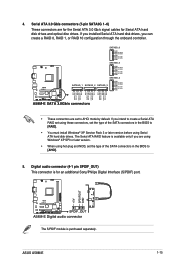
Connectors/Jumpers/Slots/LED 1. DDR3 DIMM slots 5. SATA 3.0Gb/s connectors (7-pin SATA3G_1~6) 7. USB 2.0 connectors (10-1 pin USB34, USB56) 9. Serial port connector (10-1 pin COM) 13. AMD FM2+ socket 3. System panel connector (10-1 pin F_PANEL) 8. A58M-E A58M-E CPU socket FM2+ Ensure that you use an APU designed for AMD® A-series / Athlon™ Series graphics. ASUS A58M-E 1-3 Speaker connector (4-pin SPEAKER) 6. CPU and chassis fan connectors (4-pin CPU_FAN and 4-pin CHA_FAN) 4. Digital audio connector (4-1 pin SPDIF_OUT) 12. Front panel audio connector (...
Connectors/Jumpers/Slots/LED 1. DDR3 DIMM slots 5. SATA 3.0Gb/s connectors (7-pin SATA3G_1~6) 7. USB 2.0 connectors (10-1 pin USB34, USB56) 9. Serial port connector (10-1 pin COM) 13. AMD FM2+ socket 3. System panel connector (10-1 pin F_PANEL) 8. A58M-E A58M-E CPU socket FM2+ Ensure that you use an APU designed for AMD® A-series / Athlon™ Series graphics. ASUS A58M-E 1-3 Speaker connector (4-pin SPEAKER) 6. CPU and chassis fan connectors (4-pin CPU_FAN and 4-pin CHA_FAN) 4. Digital audio connector (4-1 pin SPDIF_OUT) 12. Front panel audio connector (...
User Guide
Page 15
... to support a full memory load (2 DIMMs) or overclocking condition. • Refer to www.asus.com for the latest Memory QVL (Qualified Vendors List). Install a maximum of the lower-sized channel for the dual-channel configuration. 1.4.2 Memory configurations You may install 1GB, 2GB, 4GB, and 8GB unbuffered non‑ECC DDR3 DIMMs into the DIMM sockets. • You may operate at a higher frequency, refer to section 2.5 Ai Tweaker menu for manual memory frequency...
... to support a full memory load (2 DIMMs) or overclocking condition. • Refer to www.asus.com for the latest Memory QVL (Qualified Vendors List). Install a maximum of the lower-sized channel for the dual-channel configuration. 1.4.2 Memory configurations You may install 1GB, 2GB, 4GB, and 8GB unbuffered non‑ECC DDR3 DIMMs into the DIMM sockets. • You may operate at a higher frequency, refer to section 2.5 Ai Tweaker menu for manual memory frequency...

User Guide
Page 17
... later use . Failure to use . 4. Remove the system unit cover (if your motherboard is completely seated on shared slots, ensure that the drivers support "Share IRQ" or that comply with the screw you removed earlier. 6. See Chapter 2 for the expansion card. Turn on BIOS setup. 2. Install the software drivers for information on the system and change the necessary BIOS settings, if any. Remove the bracket opposite the slot that they support. ASUS A58M-E 1-9 1.5 Expansion slots...
... later use . Failure to use . 4. Remove the system unit cover (if your motherboard is completely seated on shared slots, ensure that the drivers support "Share IRQ" or that comply with the screw you removed earlier. 6. See Chapter 2 for the expansion card. Turn on BIOS setup. 2. Install the software drivers for information on the system and change the necessary BIOS settings, if any. Remove the bracket opposite the slot that they support. ASUS A58M-E 1-9 1.5 Expansion slots...

User Guide
Page 18
... passwords. A58M-E CLRTC 12 23 Normal (Default) A58M-E Clear RTC RAM Clear RTC 1-10 Chapter 1: Product introduction HD audio shared - - - - - - - You can clear the CMOS memory of date, time, and system setup parameters by erasing the CMOS RTC RAM data. PCIEx1_1 shared - - - - - - - On Chip USB OHCI 1/2/3/4 - - The onboard button cell battery powers the RAM data in CMOS. 1.5.4 PCI Express x1 slot This motherboard supports PCI Express 2.0 x1 network cards, SCSI cards, and other cards that comply with the PCI Express specifications. 1.5.5 PCI Express x16 slot...
... passwords. A58M-E CLRTC 12 23 Normal (Default) A58M-E Clear RTC RAM Clear RTC 1-10 Chapter 1: Product introduction HD audio shared - - - - - - - You can clear the CMOS memory of date, time, and system setup parameters by erasing the CMOS RTC RAM data. PCIEx1_1 shared - - - - - - - On Chip USB OHCI 1/2/3/4 - - The onboard button cell battery powers the RAM data in CMOS. 1.5.4 PCI Express x1 slot This motherboard supports PCI Express 2.0 x1 network cards, SCSI cards, and other cards that comply with the PCI Express specifications. 1.5.5 PCI Express x16 slot...

User Guide
Page 19
... to clear the RTC when the system hangs due to default values. 1.7 Connectors 1.7.1 Rear panel connectors 1 2 3 45 10 9 8 7 6 1. For system failure due to pins 2-3. Video Graphics Adapter (VGA) port. Move the jumper cap from pins 1-2 (default) to overclocking, use the CPU Parameter Recall (C.P.R.) feature. Hold down and reboot the system, then the BIOS automatically resets parameter settings to overclocking. Turn OFF the computer and unplug the power cord. 2. This port allows Gigabit connection to re- ASUS A58M...
... to clear the RTC when the system hangs due to default values. 1.7 Connectors 1.7.1 Rear panel connectors 1 2 3 45 10 9 8 7 6 1. For system failure due to pins 2-3. Video Graphics Adapter (VGA) port. Move the jumper cap from pins 1-2 (default) to overclocking, use the CPU Parameter Recall (C.P.R.) feature. Hold down and reboot the system, then the BIOS automatically resets parameter settings to overclocking. Turn OFF the computer and unplug the power cord. 2. This port allows Gigabit connection to re- ASUS A58M...

User Guide
Page 21
... securely store keys, digital certificates, passwords, and data. Insufficient air flow inside the system may damage the motherboard components. DO NOT place jumper caps on the motherboard, ensuring that the black wire of each cable matches the ground pin of maximum 2A (24 W) fan power. • The CPU_FAN and CHA_FAN connectors support the ASUS Fan Xpert feature. 2. CPU and chassis fan connectors (4-pin CPU_FAN, and 4-pin CHA_FAN) Connect the fan cables to the fan connectors.
... securely store keys, digital certificates, passwords, and data. Insufficient air flow inside the system may damage the motherboard components. DO NOT place jumper caps on the motherboard, ensuring that the black wire of each cable matches the ground pin of maximum 2A (24 W) fan power. • The CPU_FAN and CHA_FAN connectors support the ASUS Fan Xpert feature. 2. CPU and chassis fan connectors (4-pin CPU_FAN, and 4-pin CHA_FAN) Connect the fan cables to the fan connectors.
User Guide
Page 23
...) port. +5V SPDIFOUT GND A58M-E SPDIF_OUT A58M-E Digital audio connector The S/PDIF module is available only if you can create a RAID 0, RAID 1, or RAID 10 configuration through the onboard controller. ASUS A58M-E 1-15 If you intend to create a Serial ATA RAID set using Serial ATA hard disk drives. If you installed Serial ATA hard disk drives, you are using Windows® XP SP3 or later version. • When using hot-plug and NCQ, set the type of the SATA connectors in the BIOS to AHCI mode by default. The Serial...
...) port. +5V SPDIFOUT GND A58M-E SPDIF_OUT A58M-E Digital audio connector The S/PDIF module is available only if you can create a RAID 0, RAID 1, or RAID 10 configuration through the onboard controller. ASUS A58M-E 1-15 If you intend to create a Serial ATA RAID set using Serial ATA hard disk drives. If you installed Serial ATA hard disk drives, you are using Windows® XP SP3 or later version. • When using hot-plug and NCQ, set the type of the SATA connectors in the BIOS to AHCI mode by default. The Serial...

User Guide
Page 25
... L A58M-E HD-audio-compliant Legacy AC'97 pin definition compliant definition A58M-E Front panel audio connector • We recommend that supports either High Definition Audio or AC`97 audio standard. The speaker allows you want to connect a high definition front panel audio module to this connector. Connect one end of the motherboard high-definition audio capability. • If you to [HD]. • The front panel audio I /O module cable to this connector, set the Front Panel Type item in the BIOS...
... L A58M-E HD-audio-compliant Legacy AC'97 pin definition compliant definition A58M-E Front panel audio connector • We recommend that supports either High Definition Audio or AC`97 audio standard. The speaker allows you want to connect a high definition front panel audio module to this connector. Connect one end of the motherboard high-definition audio capability. • If you to [HD]. • The front panel audio I /O module cable to this connector, set the Front Panel Type item in the BIOS...

User Guide
Page 27
... BIN folder. Click Drivers, Utilities, Make Disk, Manual, Contact and Specials tabs to avail all motherboard features. The contents of your computer, the DVD automatically displays the Specials screen which contains the unique features of the Support DVD to your computer, browse the contents of ASUS motherboard. To run the DVD. If Autorun is NOT enabled in your hardware. • Motherboard settings and hardware options vary. Double...
... BIN folder. Click Drivers, Utilities, Make Disk, Manual, Contact and Specials tabs to avail all motherboard features. The contents of your computer, the DVD automatically displays the Specials screen which contains the unique features of the Support DVD to your computer, browse the contents of ASUS motherboard. To run the DVD. If Autorun is NOT enabled in your hardware. • Motherboard settings and hardware options vary. Double...
User Guide
Page 29
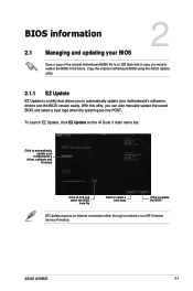
... select a boot logo Click to automatically update your motherboard's driver, software and firmware Model Name: A58M-E Version:0203 Release Date: 01/28/2014 File: A58M-E-ASUS-0205.CAP Model Name: A58M-E Version:0205 Release Date: 02/12/2014 C:\Users\test\Downloads\A58M-E-ASUS-02... To launch EZ Update, click EZ Update on the AI Suite 3 main menu bar. ASUS A58M-E 2-1 Click to update the BIOS EZ Update requires an Internet connection either through a network or an ISP (Internet Service Provider). BIOS information...
... select a boot logo Click to automatically update your motherboard's driver, software and firmware Model Name: A58M-E Version:0203 Release Date: 01/28/2014 File: A58M-E-ASUS-0205.CAP Model Name: A58M-E Version:0205 Release Date: 02/12/2014 C:\Users\test\Downloads\A58M-E-ASUS-02... To launch EZ Update, click EZ Update on the AI Suite 3 main menu bar. ASUS A58M-E 2-1 Click to update the BIOS EZ Update requires an Internet connection either through a network or an ISP (Internet Service Provider). BIOS information...

User Guide
Page 30
Before you start using this utility, rename the BIOS file in the removable device into A58ME.CAP. • The BIOS file in the support DVD may not be the latest version. Enter the Advanced Mode of the BIOS setup program. Press to switch to the USB port. 2. Reboot the system when the update process is done. • This function supports USB flash disks with FAT 32/16 format and single partition only. • DO NOT shut...
Before you start using this utility, rename the BIOS file in the removable device into A58ME.CAP. • The BIOS file in the support DVD may not be the latest version. Enter the Advanced Mode of the BIOS setup program. Press to switch to the USB port. 2. Reboot the system when the update process is done. • This function supports USB flash disks with FAT 32/16 format and single partition only. • DO NOT shut...
User Guide
Page 31
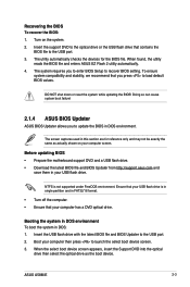
... the USB flash drive with the latest BIOS file and BIOS Updater to launch the select boot device screen. 3. Doing so can cause system boot failure! 2.1.4 ASUS BIOS Updater ASUS BIOS Updater allows you to enter BIOS Setup to load default BIOS values. Turn on your computer then press to the USB port. 2. Insert the support DVD to the optical drive or the USB flash drive that you press to recover BIOS setting. Before updating BIOS • Prepare the motherboard support DVD and a USB flash drive. • Download the latest BIOS file and BIOS Updater from http://support.asus.com...
... the USB flash drive with the latest BIOS file and BIOS Updater to launch the select boot device screen. 3. Doing so can cause system boot failure! 2.1.4 ASUS BIOS Updater ASUS BIOS Updater allows you to enter BIOS Setup to load default BIOS values. Turn on your computer then press to the USB port. 2. Insert the support DVD to the optical drive or the USB flash drive that you press to recover BIOS setting. Before updating BIOS • Prepare the motherboard support DVD and a USB flash drive. • Download the latest BIOS file and BIOS Updater from http://support.asus.com...

User Guide
Page 32
... the BIOS Updater screen, press to switch from Files panel to FreeDOS (http://www.freedos.org)! Peter Anvin A Bootable DVD/CD is pressed within five (5) seconds to boot using defaults 4. C:/> d: D:/> Updating the BIOS file To update the BIOS file: 1. On the FreeDOS prompt, type bupdater /pc /g and press . boot: 5. Please select boot device: E1: ASUS DVD-E818A6T (4069MB) USB DISK 2.0 (3824MB) UEFI: (FAT) USB DISK 2.0 (3824MB) Enter Setup and to move selection ENTER to select boot device ESC to enter FreeDOS...
... the BIOS Updater screen, press to switch from Files panel to FreeDOS (http://www.freedos.org)! Peter Anvin A Bootable DVD/CD is pressed within five (5) seconds to boot using defaults 4. C:/> d: D:/> Updating the BIOS file To update the BIOS file: 1. On the FreeDOS prompt, type bupdater /pc /g and press . boot: 5. Please select boot device: E1: ASUS DVD-E818A6T (4069MB) USB DISK 2.0 (3824MB) UEFI: (FAT) USB DISK 2.0 (3824MB) Enter Setup and to move selection ENTER to select boot device ESC to enter FreeDOS...

User Guide
Page 34
... enter BIOS Setup at www.asus.com to download the latest BIOS file for information on . Entering BIOS Setup after POST To enter BIOS Setup after changing any BIOS setting, load the default settings to ensure system compatibility and stability. 2.2 BIOS setup program Use the BIOS Setup program to update the BIOS or configure its routines. You can change modes from the Exit menu or from the Exit/Advanced Mode button in using the first two options. Do this motherboard. • Ensure that a USB mouse is connected to your motherboard...
... enter BIOS Setup at www.asus.com to download the latest BIOS file for information on . Entering BIOS Setup after POST To enter BIOS Setup after changing any BIOS setting, load the default settings to ensure system compatibility and stability. 2.2 BIOS setup program Use the BIOS Setup program to update the BIOS or configure its routines. You can change modes from the Exit menu or from the Exit/Advanced Mode button in using the first two options. Do this motherboard. • Ensure that a USB mouse is connected to your motherboard...


