A55BM-E User's Manual
Page 2
... obtain the corresponding source code and your request please provide the name, model number and version, as source code archives, etc. ASUSTeK is dependent on the preferred carrier and the location where you to this information. ii SPECIFICATIONS AND INFORMATION CONTAINED IN THIS MANUAL ARE FURNISHED FOR INFORMATIONAL USE ONLY, AND ARE SUBJECT TO CHANGE AT ANY TIME WITHOUT...
... obtain the corresponding source code and your request please provide the name, model number and version, as source code archives, etc. ASUSTeK is dependent on the preferred carrier and the location where you to this information. ii SPECIFICATIONS AND INFORMATION CONTAINED IN THIS MANUAL ARE FURNISHED FOR INFORMATIONAL USE ONLY, AND ARE SUBJECT TO CHANGE AT ANY TIME WITHOUT...

A55BM-E User's Manual
Page 4
... area where it supports. • Chapter 2: BIOS information This chapter tells how to change system settings through the BIOS Setup menus. About this guide is set to fix it , carefully read all power cables from connectors, slots, sockets and circuitry. • Avoid dust, humidity, and temperature extremes. iv Contact a qualified service technician or your retailer. Operation safety • Before installing the motherboard and adding devices on a stable surface...
... area where it supports. • Chapter 2: BIOS information This chapter tells how to change system settings through the BIOS Setup menus. About this guide is set to fix it , carefully read all power cables from connectors, slots, sockets and circuitry. • Avoid dust, humidity, and temperature extremes. iv Contact a qualified service technician or your retailer. Operation safety • Before installing the motherboard and adding devices on a stable surface...
A55BM-E User's Manual
Page 6
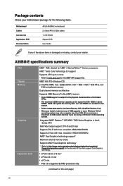
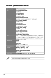
... with max. A55BM-E specifications summary CPU Chipset Memory Graphics Expansion slots AMD® FM2+ Socket for AMD® A-Series/Athlon™ Series processors AMD® Turbo Core Technology 3.0 support Supports APU up to 4 cores • Refer to the physical characteristics of 2G Supports AMD® Dual Graphics technology * Refer to http://www.amd.com/us/products/technologies/dual-graphics/ Pages/dual-graphics.aspx#3 for the discrete GPUs which support Dual Graphics technology. 1 x PCIe 3.0/2.0 x16 slot* 1 x PCIe 2.0 x1 slot 1 x PCI slot • PCIe 3.0 is subject to www.asus.com...
... with max. A55BM-E specifications summary CPU Chipset Memory Graphics Expansion slots AMD® FM2+ Socket for AMD® A-Series/Athlon™ Series processors AMD® Turbo Core Technology 3.0 support Supports APU up to 4 cores • Refer to the physical characteristics of 2G Supports AMD® Dual Graphics technology * Refer to http://www.amd.com/us/products/technologies/dual-graphics/ Pages/dual-graphics.aspx#3 for the discrete GPUs which support Dual Graphics technology. 1 x PCIe 3.0/2.0 x16 slot* 1 x PCIe 2.0 x1 slot 1 x PCI slot • PCIe 3.0 is subject to www.asus.com...
A55BM-E User's Manual
Page 7
... heatsink solution - ASUS EZ Flash 2 - A55BM-E specifications summary Storage / RAID LAN Audio USB ASUS unique features AMD® A55 FCH: - 6 x Serial ATA 3.0Gb/s connectors (dark brown) support RAID 0, RAID 1, RAID 10, and JBOD configurations Realtek® 8111G Gigabit LAN controller Realtek® ALC887-VD 8-channel High Definition Audio CODEC • Use a chassis with HD audio module in the front panel to ensure the best quality, reliability, and durability ASUS Digi+ VRM - ASUS DIGI+ VRM: Digital Power Design for extended component lifespan ASUS High...
... heatsink solution - ASUS EZ Flash 2 - A55BM-E specifications summary Storage / RAID LAN Audio USB ASUS unique features AMD® A55 FCH: - 6 x Serial ATA 3.0Gb/s connectors (dark brown) support RAID 0, RAID 1, RAID 10, and JBOD configurations Realtek® 8111G Gigabit LAN controller Realtek® ALC887-VD 8-channel High Definition Audio CODEC • Use a chassis with HD audio module in the front panel to ensure the best quality, reliability, and durability ASUS Digi+ VRM - ASUS DIGI+ VRM: Digital Power Design for extended component lifespan ASUS High...
A55BM-E User's Manual
Page 8
...support additional 4 USB 2.0 ports 6 x SATA 3.0Gb/s connectors 1 x COM connector 1 x LPT connector 1 x System panel connector 1 x Internal Speaker connector 1 x 4-pin CPU fan connector 1 x S/PDIF output connector 1 x 4-pin Chassis fan connector 1 x Front panel audio connector 1 x 24-pin EATX power connector 1 x 4-pin ATX 12V power connector 64 Mb Flash ROM, UEFI AMI BIOS, PnP, DMI 2.0, WfM 2.0, SM BIOS 2.6, ACPI 2.0a, Multi-language BIOS, ASUS CrashFree BIOS 3, F12 Printscreen function, F3 Shortcut function, and ASUS DRAM SPD (Serial Presence Detect) memory information Drivers ASUS Update ASUS...
...support additional 4 USB 2.0 ports 6 x SATA 3.0Gb/s connectors 1 x COM connector 1 x LPT connector 1 x System panel connector 1 x Internal Speaker connector 1 x 4-pin CPU fan connector 1 x S/PDIF output connector 1 x 4-pin Chassis fan connector 1 x Front panel audio connector 1 x 24-pin EATX power connector 1 x 4-pin ATX 12V power connector 64 Mb Flash ROM, UEFI AMI BIOS, PnP, DMI 2.0, WfM 2.0, SM BIOS 2.6, ACPI 2.0a, Multi-language BIOS, ASUS CrashFree BIOS 3, F12 Printscreen function, F3 Shortcut function, and ASUS DRAM SPD (Serial Presence Detect) memory information Drivers ASUS Update ASUS...
A55BM-E User's Manual
Page 9
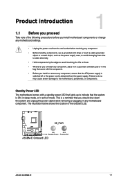
... Power Powered Off A55BM-E Onboard LED ASUS A55BM-E 1-1 The illustration below shows the location of the following precautions before you install motherboard components or change any motherboard component. Product introduction 1 1.1 Before you proceed Take note of the onboard LED. Standby Power LED The motherboard comes with the component. • Before you install or remove any component, ensure that the system is detached from the wall socket before removing or plugging in any motherboard settings...
... Power Powered Off A55BM-E Onboard LED ASUS A55BM-E 1-1 The illustration below shows the location of the following precautions before you install motherboard components or change any motherboard component. Product introduction 1 1.1 Before you proceed Take note of the onboard LED. Standby Power LED The motherboard comes with the component. • Before you install or remove any component, ensure that the system is detached from the wall socket before removing or plugging in any motherboard settings...

A55BM-E User's Manual
Page 11
... chassis fan connectors (4-pin CPU_FAN and 4-pin CHA_FAN) 5. Clear RTC RAM (3-pin CLRTC) 10. Digital audio connector (4-1 pin SPDIF_OUT) 15. System panel connector (10-1 pin F_PANEL) 9. LPT connector (26-1 pin LPT) 14. ATX power connectors (24-pin EATXPWR, 4-pin ATX12V) 3. AMD FM2+ socket 4. DDR3 DIMM slots 6. USB device wake-up (3-pin KB_USBPWB) 2. Front panel audio connector (10-1 pin AAFP) ASUS A55BM-E Page 1-13 1-16 1-4 1-15 1-7 1-18 1-17 1-18 1-11 1-1 1-20 1-12 1-21 1-19 1-20 1-19 1-3 Speaker connector (4-pin SPEAKER) 7. USB 2.0 connectors (10-1 pin USB34, USB56) 12. Serial...
... chassis fan connectors (4-pin CPU_FAN and 4-pin CHA_FAN) 5. Clear RTC RAM (3-pin CLRTC) 10. Digital audio connector (4-1 pin SPDIF_OUT) 15. System panel connector (10-1 pin F_PANEL) 9. LPT connector (26-1 pin LPT) 14. ATX power connectors (24-pin EATXPWR, 4-pin ATX12V) 3. AMD FM2+ socket 4. DDR3 DIMM slots 6. USB device wake-up (3-pin KB_USBPWB) 2. Front panel audio connector (10-1 pin AAFP) ASUS A55BM-E Page 1-13 1-16 1-4 1-15 1-7 1-18 1-17 1-18 1-11 1-1 1-20 1-12 1-21 1-19 1-20 1-19 1-3 Speaker connector (4-pin SPEAKER) 7. USB 2.0 connectors (10-1 pin USB34, USB56) 12. Serial...
A55BM-E User's Manual
Page 16
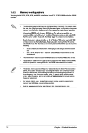
... motherboard does not support DIMMs made up of 512Mb (64MB) chips or less. • The maximum 32GB memory capacity can be supported with 16GB or above DIMMs. ASUS will update the memory QVL once the DIMMs are using a 32-bit Windows® OS. - The system maps the total size of the lower-sized channel for overclocking may install varying memory sizes in the market. • The default memory operation frequency is...
... motherboard does not support DIMMs made up of 512Mb (64MB) chips or less. • The maximum 32GB memory capacity can be supported with 16GB or above DIMMs. ASUS will update the memory QVL once the DIMMs are using a 32-bit Windows® OS. - The system maps the total size of the lower-sized channel for overclocking may install varying memory sizes in the market. • The default memory operation frequency is...

A55BM-E User's Manual
Page 18
... PCI slot supports cards such as a LAN card, SCSI card, USB card, and other cards that you intend to the chassis with the slot and press firmly until the card is already installed in a chassis). 3. Remove the bracket opposite the slot that comply with it by adjusting the software settings. 1. Replace the system cover. 1.5.2 Configuring an expansion card After installing the expansion card, configure it and make the necessary hardware settings for information on the slot. 5. Install the software drivers...
... PCI slot supports cards such as a LAN card, SCSI card, USB card, and other cards that you intend to the chassis with the slot and press firmly until the card is already installed in a chassis). 3. Remove the bracket opposite the slot that comply with it by adjusting the software settings. 1. Replace the system cover. 1.5.2 Configuring an expansion card After installing the expansion card, configure it and make the necessary hardware settings for information on the slot. 5. Install the software drivers...
A55BM-E User's Manual
Page 19
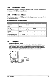
...- - 1.6 Jumpers Clear RTC RAM (3-pin CLRTC) This jumper allows you to clear the Real Time Clock (RTC) RAM in CMOS, which include system setup information such as system passwords. You can clear the CMOS memory of date, time, and system setup parameters by erasing the CMOS RTC RAM data. 1.5.4 PCI Express x1 slot This motherboard supports PCI Express 2.0 x1 network cards, SCSI cards, and other cards that comply with the PCI Express specifications. 1.5.5 PCI Express x16 slot This motherboard supports one PCI Express 3.0/2.0 x16 graphics cards that comply with the PCI Express specifications...
...- - 1.6 Jumpers Clear RTC RAM (3-pin CLRTC) This jumper allows you to clear the Real Time Clock (RTC) RAM in CMOS, which include system setup information such as system passwords. You can clear the CMOS memory of date, time, and system setup parameters by erasing the CMOS RTC RAM data. 1.5.4 PCI Express x1 slot This motherboard supports PCI Express 2.0 x1 network cards, SCSI cards, and other cards that comply with the PCI Express specifications. 1.5.5 PCI Express x16 slot This motherboard supports one PCI Express 3.0/2.0 x16 graphics cards that comply with the PCI Express specifications...
A55BM-E User's Manual
Page 20
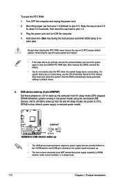
... down the key during the boot process and enter BIOS setup to re- Keep the cap on pins 2-3 for each USB port; After clearing the CMOS, reinstall the battery. • You do not help, remove the onboard battery and move the cap back to CPU, DRAM in slow refresh, power supply in reduced power mode). USB device wake-up (3-pin USBPWF) Set these jumpers to +5V to wake up from S1 sleep mode (CPU stopped, DRAM refreshed, system running in sleep mode. 1-12...
... down the key during the boot process and enter BIOS setup to re- Keep the cap on pins 2-3 for each USB port; After clearing the CMOS, reinstall the battery. • You do not help, remove the onboard battery and move the cap back to CPU, DRAM in slow refresh, power supply in reduced power mode). USB device wake-up (3-pin USBPWF) Set these jumpers to +5V to wake up from S1 sleep mode (CPU stopped, DRAM refreshed, system running in sleep mode. 1-12...

A55BM-E User's Manual
Page 21
... panel connectors 1 2 3 45 10 9 8 7 6 1. This 15-pin port is for a VGA monitor or other VGA-compatible devices. 3. ASUS A55BM-E 1-13 PS/2 Mouse port (green). Video Graphics Adapter (VGA) port. LAN (RJ-45) port. Keyboard and USB device wake up feature. This port allows Gigabit connection to enable or disable the keyboard and USB device wake-up (3-pin KB_USBPWB) This jumper allows you can supply at least 1A on the keyboard. This port is for a PS/2 mouse. 2. 3. When you set this jumper to pins 2-3 (+5VSB), you to a Local Area Network (LAN...
... panel connectors 1 2 3 45 10 9 8 7 6 1. This 15-pin port is for a VGA monitor or other VGA-compatible devices. 3. ASUS A55BM-E 1-13 PS/2 Mouse port (green). Video Graphics Adapter (VGA) port. LAN (RJ-45) port. Keyboard and USB device wake up feature. This port allows Gigabit connection to enable or disable the keyboard and USB device wake-up (3-pin KB_USBPWB) This jumper allows you can supply at least 1A on the keyboard. This port is for a PS/2 mouse. 2. 3. When you set this jumper to pins 2-3 (+5VSB), you to a Local Area Network (LAN...
A55BM-E User's Manual
Page 23
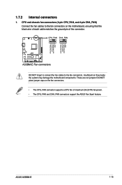
... to connect the fan cables to the fan connectors on the fan connectors. • The CPU_FAN connector supports a CPU fan of the connector. ASUS A55BM-E 1-15 CPU FAN PWM CPU FAN IN CPU FAN PWR GND CHA FAN PWM CHA FAN IN CHA FAN PWR GND 1.7.2 Internal connectors 1. CPU and chassis fan connectors (4-pin CPU_FAN, and 4-pin CHA_FAN) Connect the fan cables to the fan connectors. DO NOT place jumper caps on the motherboard, ensuring that the black wire of each cable matches the ground pin of maximum 2A (24 W) fan power. •...
... to connect the fan cables to the fan connectors on the fan connectors. • The CPU_FAN connector supports a CPU fan of the connector. ASUS A55BM-E 1-15 CPU FAN PWM CPU FAN IN CPU FAN PWR GND CHA FAN PWM CHA FAN IN CHA FAN PWR GND 1.7.2 Internal connectors 1. CPU and chassis fan connectors (4-pin CPU_FAN, and 4-pin CHA_FAN) Connect the fan cables to the fan connectors. DO NOT place jumper caps on the motherboard, ensuring that the black wire of each cable matches the ground pin of maximum 2A (24 W) fan power. •...

A55BM-E User's Manual
Page 25
... later version. • When using hot-plug and NCQ, set the type of the SATA connectors in the BIOS to [RAID]. • You must install Windows® XP Service Pack 3 or later version before using these connectors, set the type of the SATA connectors in the BIOS to AHCI mode by default. Serial ATA 3.0 Gb/s connectors (7-pin SATA3G 1~6) These connectors are set to [AHCI]. The Serial ATA RAID feature is available only if you can create a RAID 0, RAID 1, or RAID 10 configuration through the onboard controller. A55BM-E SATA3G_1...
... later version. • When using hot-plug and NCQ, set the type of the SATA connectors in the BIOS to [RAID]. • You must install Windows® XP Service Pack 3 or later version before using these connectors, set the type of the SATA connectors in the BIOS to AHCI mode by default. Serial ATA 3.0 Gb/s connectors (7-pin SATA3G 1~6) These connectors are set to [AHCI]. The Serial ATA RAID feature is available only if you can create a RAID 0, RAID 1, or RAID 10 configuration through the onboard controller. A55BM-E SATA3G_1...

A55BM-E User's Manual
Page 27
... motherboard high-definition audio capability. • If you want to connect a high definition front panel audio module to [HD]. • The front panel audio I/O module is for an additional Sony/Philips Digital Interface (S/PDIF) port. +5V SPDIFOUT GND 6. A55BM-E SPDIF_OUT A55BM-E Digital audio connector The S/PDIF module is for a chassis-mounted front panel audio I /O module cable to this connector, set the Front Panel Type item in the BIOS to this connector. Digital audio connector (4-1 pin SPDIF_OUT) This connector...
... motherboard high-definition audio capability. • If you want to connect a high definition front panel audio module to [HD]. • The front panel audio I/O module is for an additional Sony/Philips Digital Interface (S/PDIF) port. +5V SPDIFOUT GND 6. A55BM-E SPDIF_OUT A55BM-E Digital audio connector The S/PDIF module is for a chassis-mounted front panel audio I /O module cable to this connector, set the Front Panel Type item in the BIOS to this connector. Digital audio connector (4-1 pin SPDIF_OUT) This connector...
A55BM-E User's Manual
Page 29
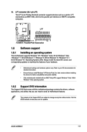
... versions before installing the drivers for updates. Always install the latest OS version and corresponding updates to maximize the features of the Support DVD are subject to your hardware. • Motherboard settings and hardware options vary. ASUS A55BM-E 1-21 LPT connector (26-1 pin LPT) The LPT (Line Printing Terminal) connector supports devices such as IEEE 1284, which is the parallel port interface on IBM PC-compatible computers. Refer to change at www.asus...
... versions before installing the drivers for updates. Always install the latest OS version and corresponding updates to maximize the features of the Support DVD are subject to your hardware. • Motherboard settings and hardware options vary. ASUS A55BM-E 1-21 LPT connector (26-1 pin LPT) The LPT (Line Printing Terminal) connector supports devices such as IEEE 1284, which is the parallel port interface on IBM PC-compatible computers. Refer to change at www.asus...

A55BM-E User's Manual
Page 31
... Update requires an Internet connection either through a network or an ISP (Internet Service Provider). ASUS A55BM-E 2-1 BIOS information 2.1 Managing and updating your motherboard's driver, software and firmware Model Name: H81-PLUS Version:0203 Release Date: 05/28/2013 File: H81-PLUS-ASUS-0205.CAP Model Name: H81-PLUS Version:0205 Release Date: 06/18/2013 C:\Users\test\Downloads\H81-PLUS-ASUS-02... To launch EZ Update, click EZ Update on the AI Suite 3 main menu...
... Update requires an Internet connection either through a network or an ISP (Internet Service Provider). ASUS A55BM-E 2-1 BIOS information 2.1 Managing and updating your motherboard's driver, software and firmware Model Name: H81-PLUS Version:0203 Release Date: 05/28/2013 File: H81-PLUS-ASUS-0205.CAP Model Name: H81-PLUS Version:0205 Release Date: 06/18/2013 C:\Users\test\Downloads\H81-PLUS-ASUS-02... To launch EZ Update, click EZ Update on the AI Suite 3 main menu...
A55BM-E User's Manual
Page 32
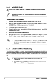
... while updating the BIOS to prevent system boot failure! 2.1.3 ASUS CrashFree BIOS 3 utility The ASUS CrashFree BIOS 3 is an auto recovery tool that contains the latest BIOS file to the USB port. 2. Enter the Advanced Mode of the BIOS setup program. Go to the Tool menu to select ASUS EZ Flash 2 Utility and press to the Folder Info field. 6. Download the latest BIOS file from the ASUS website at www.asus.com. 2-2 Chapter 2: Getting started Press to switch to enable it...
... while updating the BIOS to prevent system boot failure! 2.1.3 ASUS CrashFree BIOS 3 utility The ASUS CrashFree BIOS 3 is an auto recovery tool that contains the latest BIOS file to the USB port. 2. Enter the Advanced Mode of the BIOS setup program. Go to the Tool menu to select ASUS EZ Flash 2 Utility and press to the Folder Info field. 6. Download the latest BIOS file from the ASUS website at www.asus.com. 2-2 Chapter 2: Getting started Press to switch to enable it...

A55BM-E User's Manual
Page 33
... SATA hard disk drives (optional). DO NOT shut down or reset the system while updating the BIOS! Download the latest BIOS file and BIOS Updater from the ASUS website at http://support.asus.com and save the BIOS file and BIOS Updater to update BIOS in DOS environment. ASUS A55BM-E 2-3 Recovering the BIOS To recover the BIOS: 1. Insert the support DVD to the optical drive or the USB flash drive that you can cause system boot failure! 2.1.4 ASUS BIOS Updater The ASUS BIOS Updater allows you to enter BIOS Setup to the USB port. 3. The utility...
... SATA hard disk drives (optional). DO NOT shut down or reset the system while updating the BIOS! Download the latest BIOS file and BIOS Updater from the ASUS website at http://support.asus.com and save the BIOS file and BIOS Updater to update BIOS in DOS environment. ASUS A55BM-E 2-3 Recovering the BIOS To recover the BIOS: 1. Insert the support DVD to the optical drive or the USB flash drive that you can cause system boot failure! 2.1.4 ASUS BIOS Updater The ASUS BIOS Updater allows you to enter BIOS Setup to the USB port. 3. The utility...

A55BM-E User's Manual
Page 35
... connect all SATA hard disk drives after updating BIOS. • Ensure to load the BIOS default settings to guide you in using the first two options. Entering BIOS Setup at startup To enter BIOS Setup at startup: • Press during the Power-On Self Test (POST). ASUS A55BM-E 2-5 BIOS Updater checks the selected BIOS file and prompts you failed to confirm BIOS update. 4. Do this option only if you to enter BIOS Setup using the BIOS Setup program. DO NOT shut down or reset the system while updating the BIOS...
... connect all SATA hard disk drives after updating BIOS. • Ensure to load the BIOS default settings to guide you in using the first two options. Entering BIOS Setup at startup To enter BIOS Setup at startup: • Press during the Power-On Self Test (POST). ASUS A55BM-E 2-5 BIOS Updater checks the selected BIOS file and prompts you failed to confirm BIOS update. 4. Do this option only if you to enter BIOS Setup using the BIOS Setup program. DO NOT shut down or reset the system while updating the BIOS...


