
Owners Manual
Page 1
... Princes Highway, Hallam Victoria 3803, Australia Phone 03-8787-1200 ALPINE ELECTRONICS GmbH Wilhelm-Wagenfeld-Str. 1-3, 80807 Munchen, Germany Phone 089-32 42 640 ALPINE ELECTRONICS OF U.K. VISUAL PARKING ASSIST SENSOR SYSTEM (VPASS) VPX-B104R • OWNER'S MANUAL Please read before using this equipment. • MODE D'EMPLOI Veuillez lire avant d,utiliser cet appareil. • MANUAL DE OPERACION Lealo antes de utilizar...
... Princes Highway, Hallam Victoria 3803, Australia Phone 03-8787-1200 ALPINE ELECTRONICS GmbH Wilhelm-Wagenfeld-Str. 1-3, 80807 Munchen, Germany Phone 089-32 42 640 ALPINE ELECTRONICS OF U.K. VISUAL PARKING ASSIST SENSOR SYSTEM (VPASS) VPX-B104R • OWNER'S MANUAL Please read before using this equipment. • MODE D'EMPLOI Veuillez lire avant d,utiliser cet appareil. • MANUAL DE OPERACION Lealo antes de utilizar...
Owners Manual
Page 2
... 3 NOTICE 5 Sensor Operation Introduction 6 Important Information 6 How the Visual Parking Assist Sensor System Works 6 Installation and Connections Installation Diagram 7 1. Pickup Truck 7 Accessory Parts 8 Component 8 Installation Tool 8 Wire Connection 9 Painting Sensor Cover and Sensor Unit 10 Sensor Assembly Painting Method....... 10 Sensor Assembly 11 Installation of Sensor 13 Installation of ECU 15 On-Screen Display Set Up 15 Fish-eye Correction Menu 16 Parking Guide Line Adjustment 16 Diagnostic 17 Setup Mode Structure Tree 18...
... 3 NOTICE 5 Sensor Operation Introduction 6 Important Information 6 How the Visual Parking Assist Sensor System Works 6 Installation and Connections Installation Diagram 7 1. Pickup Truck 7 Accessory Parts 8 Component 8 Installation Tool 8 Wire Connection 9 Painting Sensor Cover and Sensor Unit 10 Sensor Assembly Painting Method....... 10 Sensor Assembly 11 Installation of Sensor 13 Installation of ECU 15 On-Screen Display Set Up 15 Fish-eye Correction Menu 16 Parking Guide Line Adjustment 16 Diagnostic 17 Setup Mode Structure Tree 18...

Owners Manual
Page 3
... is seen through the rearview mirror. WHEN INSTALLING OR CHECKING A CAMERA AND/OR SENSOR, DO SO AFTER PARKING THE CAR IN A LEVEL, SAFE PLACE, TURNING OFF THE ENGINE, AND APPLYING THE HAND BRAKE. WHEN INSTALLING CAMERA AND/OR SENSOR, BE SURE TO USE SPECIFIC VEHICLE CALIBRATION KIT OTHERWISE IT WILL NOT ACCURATELY DISPLAY IMAGES. MINIMIZE DISPLAY VIEWING WHILE DRIVING. Do not tap into...
... is seen through the rearview mirror. WHEN INSTALLING OR CHECKING A CAMERA AND/OR SENSOR, DO SO AFTER PARKING THE CAR IN A LEVEL, SAFE PLACE, TURNING OFF THE ENGINE, AND APPLYING THE HAND BRAKE. WHEN INSTALLING CAMERA AND/OR SENSOR, BE SURE TO USE SPECIFIC VEHICLE CALIBRATION KIT OTHERWISE IT WILL NOT ACCURATELY DISPLAY IMAGES. MINIMIZE DISPLAY VIEWING WHILE DRIVING. Do not tap into...
Owners Manual
Page 4
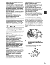
... product failure. Arrange wiring and cables in close proximity to the area around the vehicle. USE THIS PRODUCT FOR MOBILE 12V APPLICATIONS. HAVE THE WIRING AND INSTALLATION DONE BY EXPERTS. To ensure the sensors function accurately, never install accessories in compliance with your authorized Alpine dealer or the nearest Alpine Service Center for repairing. Use for adjusting parking guideline. Calibration may result in fire...
... product failure. Arrange wiring and cables in close proximity to the area around the vehicle. USE THIS PRODUCT FOR MOBILE 12V APPLICATIONS. HAVE THE WIRING AND INSTALLATION DONE BY EXPERTS. To ensure the sensors function accurately, never install accessories in compliance with your authorized Alpine dealer or the nearest Alpine Service Center for repairing. Use for adjusting parking guideline. Calibration may result in fire...
Owners Manual
Page 5
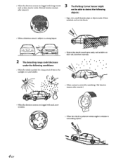
... icicles. • When the vehicle is subject to surrounding objects. 4:.EN D .·..- - 2 The detecting range could decrease under the following objects: • Rope, wire, small-diameter pipes or objects made of these materials, such as fabrics or other soft, absorbent materials. •... detect the following conditions: • When the vehicle is parked for a long period of time in the sunlight or in cold weather. • Objects that absorb sound waves easily, such as wire fences. • When a detection sensor is parked at extreme angles in relation to a ...
... icicles. • When the vehicle is subject to surrounding objects. 4:.EN D .·..- - 2 The detecting range could decrease under the following objects: • Rope, wire, small-diameter pipes or objects made of these materials, such as fabrics or other soft, absorbent materials. •... detect the following conditions: • When the vehicle is parked for a long period of time in the sunlight or in cold weather. • Objects that absorb sound waves easily, such as wire fences. • When a detection sensor is parked at extreme angles in relation to a ...

Owners Manual
Page 6
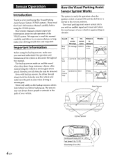
...Caring for the Backup Sensors 1. NOTICE • When washing the vehicle, do not use of touch-up paint (retail product) for rust-prevention, and should be prepared beforehand. • Route the cables and wiring away from above the floor. for example: no beep, slow beep, fast beep or...cords, or may result in shortcircuit, fire or electric shock. 5-EN • When getting too close to the cable insulation, which may allow water to enter the camera and/ or object sensor. • In some cases, to attach the device, a hole must be drilled in the car body, requiring use an automatic car...
...Caring for the Backup Sensors 1. NOTICE • When washing the vehicle, do not use of touch-up paint (retail product) for rust-prevention, and should be prepared beforehand. • Route the cables and wiring away from above the floor. for example: no beep, slow beep, fast beep or...cords, or may result in shortcircuit, fire or electric shock. 5-EN • When getting too close to the cable insulation, which may allow water to enter the camera and/ or object sensor. • In some cases, to attach the device, a hole must be drilled in the car body, requiring use an automatic car...
Owners Manual
Page 7
... using the backup sensors, make sure the path is approaching an obstacle. WARNING RED tinuous beep Within 0.7-1.5 ft Back Sensor 6-EN Corner Sensor Cil:l n ,cD.l. always look behind you with backup sensors, the driver should always look for operation when the ignition switch is turned ON and the shift lever is moved to help make an audible sound...
... using the backup sensors, make sure the path is approaching an obstacle. WARNING RED tinuous beep Within 0.7-1.5 ft Back Sensor 6-EN Corner Sensor Cil:l n ,cD.l. always look behind you with backup sensors, the driver should always look for operation when the ignition switch is turned ON and the shift lever is moved to help make an audible sound...
Owners Manual
Page 8
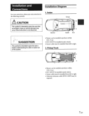
...). • ECU MUST be installed inside vehicle. • Sensor cable must be installed from left to right. • Optional extension cable (KWE-104PS) may occur if the instruction is not observed. Installation and Connections For your protection, please pay extra attention to the following symbols. ~CAUTION This symbol is intended to alert the user that an accident, injury...
...). • ECU MUST be installed inside vehicle. • Sensor cable must be installed from left to right. • Optional extension cable (KWE-104PS) may occur if the instruction is not observed. Installation and Connections For your protection, please pay extra attention to the following symbols. ~CAUTION This symbol is intended to alert the user that an accident, injury...
Owners Manual
Page 9
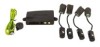
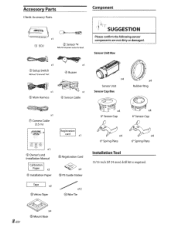
... Component section for detail. Sensor Unit Box x1 @ Setup Switch Without "Grommet" Part x1 @Buzzer x1 @Main Harness - x1 @Sensor Cable x1 (/) Camera Cable (3.5 m) Sensor Unit Sensor Cap Box ~x4 oo Sensor Cap x4 Rubber Ring ~ ~x4 6° Sensor Cap VISO.t.li'MUIG.U.T..,_. VPX-B104R x1 x1 ® Owner's and Installation Manual x2 ® Installation Paper ®Registration Card x4 @ PS Guide Sticker x4 0° Spring...
... Component section for detail. Sensor Unit Box x1 @ Setup Switch Without "Grommet" Part x1 @Buzzer x1 @Main Harness - x1 @Sensor Cable x1 (/) Camera Cable (3.5 m) Sensor Unit Sensor Cap Box ~x4 oo Sensor Cap x4 Rubber Ring ~ ~x4 6° Sensor Cap VISO.t.li'MUIG.U.T..,_. VPX-B104R x1 x1 ® Owner's and Installation Manual x2 ® Installation Paper ®Registration Card x4 @ PS Guide Sticker x4 0° Spring...
Owners Manual
Page 10
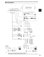
... camera to the system using the Alpine Camera connector or RCA video in for HCE-C104 or other RCA video connection f - Oth;r i C~m;r;-(RCA I I SetupSWI Buzzer 6... o Reverse Buzzer I ! Setup Switch Sensor Cable Parking Sensors For Sedan For Pickup Truck Alpine Monitor HCE-C117D M5 F5 M6 System - · ---'~-:---· -~ 1 -·5~5 i r·---Fs______ .M-:__5 M6-~6 j : (Q}--1--, ~-·1 · - . cdl •i I I i r~--H--c-e---e-1-o-4 I I JI - Wire Connection (Red) I (Orange/White) I Reverse (Black) Video in . * Connect...
... camera to the system using the Alpine Camera connector or RCA video in for HCE-C104 or other RCA video connection f - Oth;r i C~m;r;-(RCA I I SetupSWI Buzzer 6... o Reverse Buzzer I ! Setup Switch Sensor Cable Parking Sensors For Sedan For Pickup Truck Alpine Monitor HCE-C117D M5 F5 M6 System - · ---'~-:---· -~ 1 -·5~5 i r·---Fs______ .M-:__5 M6-~6 j : (Q}--1--, ~-·1 · - . cdl •i I I i r~--H--c-e---e-1-o-4 I I JI - Wire Connection (Red) I (Orange/White) I Reverse (Black) Video in . * Connect...
Owners Manual
Page 11
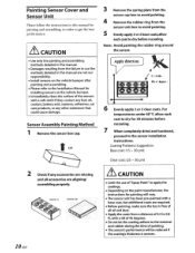
...use the methods detailed in this manual are not our responsibility. • Install sensors on the vehicle bumper after painting and assembling. • Please refer to the Installation Manual for installing sensors on the paint manufacturer, the instructions for painting will be reduced if the coating's thickness is free of all accessories... coating adhere to the terminal and rubber during the time of 0.5 to 0.8 ft, with a soft cloth if they contact any fuel, oil, coolant, battery acid, sealants, adhesives, car care products, or any accessories are missing and all oil and dust. •...
...use the methods detailed in this manual are not our responsibility. • Install sensors on the vehicle bumper after painting and assembling. • Please refer to the Installation Manual for installing sensors on the paint manufacturer, the instructions for painting will be reduced if the coating's thickness is free of all accessories... coating adhere to the terminal and rubber during the time of 0.5 to 0.8 ft, with a soft cloth if they contact any fuel, oil, coolant, battery acid, sealants, adhesives, car care products, or any accessories are missing and all oil and dust. •...
Owners Manual
Page 12
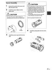
... 1 Remove the cap from the sensor unit after the paint is installed into the sensor unit. • Use Superglue where the sensor cap and sensor unit join, to increase security (Use the superglue for plastic only) 1 Bumps 3 Install the sensor cap onto the sensor unit. 4 Install the spring plate into the sensor unit. LtcAUTION The side of the sensor rubber...
... 1 Remove the cap from the sensor unit after the paint is installed into the sensor unit. • Use Superglue where the sensor cap and sensor unit join, to increase security (Use the superglue for plastic only) 1 Bumps 3 Install the sensor cap onto the sensor unit. 4 Install the spring plate into the sensor unit. LtcAUTION The side of the sensor rubber...
Owners Manual
Page 13
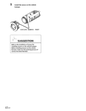
Before installing sensors on the vehicle bumper. 5 Install the sensor on the vehicle bumper, make sure the painting process of Sensor for installing sensors on the vehicle bumper. SUGGESTION Refer to the Installation of sensors has been finished. 12-EN
Before installing sensors on the vehicle bumper. 5 Install the sensor on the vehicle bumper, make sure the painting process of Sensor for installing sensors on the vehicle bumper. SUGGESTION Refer to the Installation of sensors has been finished. 12-EN
Owners Manual
Page 14
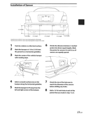
Mark the points for bumper with masking tape. 6 Divide the distance between 2 marked points into three equal lengths. Installation of Sensor 1.6 ft ( in) @52 1/3 Length 1/3 Length oo Equip the sensor with the sensor cap and spring plate for a flat bumper Equip the sensor with .... 4 Select a smooth surface area on a flat level surface. 2 Mark the bumper at 1.8 to 2.3 ft from the left and right corners of the bumper. 7 Check the size of the hole saw to match the diameter of the sensors before drilling any holes. 8 Drill a 15/16 inch hole at each of the vehicle...
Mark the points for bumper with masking tape. 6 Divide the distance between 2 marked points into three equal lengths. Installation of Sensor 1.6 ft ( in) @52 1/3 Length 1/3 Length oo Equip the sensor with the sensor cap and spring plate for a flat bumper Equip the sensor with .... 4 Select a smooth surface area on a flat level surface. 2 Mark the bumper at 1.8 to 2.3 ft from the left and right corners of the bumper. 7 Check the size of the hole saw to match the diameter of the sensors before drilling any holes. 8 Drill a 15/16 inch hole at each of the vehicle...

Owners Manual
Page 15
rrr I I "~~~ ; f~/ \ \· \ \ I ;! \\\ \ \ \ \ . / \ ~ / \ ( -JJJ(.-------~~ JI ----: -......... _ 6-- 14-EN 9 Check behind the bumper to ensure there is enough depth for sensor installation. 13 Insert the plug into the socket. 10 Install the sensor vertically, with the "UP" sign facing up. 11 Install the-sensor-into the hole and mount firmly in the bumper. 12 Route the sensor cable.
rrr I I "~~~ ; f~/ \ \· \ \ I ;! \\\ \ \ \ \ . / \ ~ / \ ( -JJJ(.-------~~ JI ----: -......... _ 6-- 14-EN 9 Check behind the bumper to ensure there is enough depth for sensor installation. 13 Insert the plug into the socket. 10 Install the sensor vertically, with the "UP" sign facing up. 11 Install the-sensor-into the hole and mount firmly in the bumper. 12 Route the sensor cable.
Owners Manual
Page 16
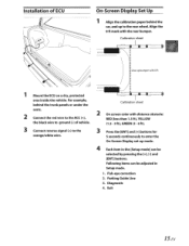
...-Screen Display set-up bumper with the rear bumper. Align the 0 ft mark with 0 ft 1 Mount the ECU on a dry, protected area inside the vehicle. Parking Guide Line 3. Calibration sheet Line up mode. 4 Each item in Setup mode. 1. Following items can be adjusted in the [Setup mode] can be selected by pressing the [+], [-] and [ENT] buttons. Exit 15-EN Fish-eye correction 2. Calibration sheet 2 On screen...
...-Screen Display set-up bumper with the rear bumper. Align the 0 ft mark with 0 ft 1 Mount the ECU on a dry, protected area inside the vehicle. Parking Guide Line 3. Calibration sheet Line up mode. 4 Each item in Setup mode. 1. Following items can be adjusted in the [Setup mode] can be selected by pressing the [+], [-] and [ENT] buttons. Exit 15-EN Fish-eye correction 2. Calibration sheet 2 On screen...
Owners Manual
Page 17
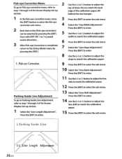
... sub-menu. 13 Select the "Line Shift Adjustment'~ Press the [ENT] to enter. 1 4 Use the [+] or [-] button to adjust the line shift to match the calibration paper. 15 Press the [ENT] to the [Setup Mode] menu by pressing the [ENT]. Start with OFF, FEC 1 to 7 to avoid screen distortion. 3 After Fish-eye Correction is completed, returrn to enter the sub-menu. 2.Parking Guide Line...
... sub-menu. 13 Select the "Line Shift Adjustment'~ Press the [ENT] to enter. 1 4 Use the [+] or [-] button to adjust the line shift to match the calibration paper. 15 Press the [ENT] to the [Setup Mode] menu by pressing the [ENT]. Start with OFF, FEC 1 to 7 to avoid screen distortion. 3 After Fish-eye Correction is completed, returrn to enter the sub-menu. 2.Parking Guide Line...
Owners Manual
Page 18
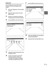
... [Setup Mode]. 9 Select the "Exit'~ Press the [ENT] to enter the sub-menu. J 5 Select the "Function Parameter'~ Press the [ENT] to enter. 6 Use the[+][-] button to review the function parameter of On-Screen Display Set-up section. 1 Select the "Diagnostic'~ Press the [ENTJ to-enter. 2 Select the "System status'~ Press the lENT] to enter. 3 Use the[+] or[-] button to review the "Firmware Version...
... [Setup Mode]. 9 Select the "Exit'~ Press the [ENT] to enter the sub-menu. J 5 Select the "Function Parameter'~ Press the [ENT] to enter. 6 Use the[+][-] button to review the function parameter of On-Screen Display Set-up section. 1 Select the "Diagnostic'~ Press the [ENTJ to-enter. 2 Select the "System status'~ Press the lENT] to enter. 3 Use the[+] or[-] button to review the "Firmware Version...
Owners Manual
Page 20
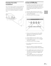
... moved to - This audio signal occurs five times and the following checks if the audible signal does not sound when the vehicle is displayed for one second. Perform the following message is approaching an obstacle. If a problem found with snow or mud. b) Check whether the sensor wires are plugged into reverse. Use a flat board (2 x 2 ft) behind the car to the sensor...
... moved to - This audio signal occurs five times and the following checks if the audible signal does not sound when the vehicle is displayed for one second. Perform the following message is approaching an obstacle. If a problem found with snow or mud. b) Check whether the sensor wires are plugged into reverse. Use a flat board (2 x 2 ft) behind the car to the sensor...

Owners Manual
Page 23
... are met. Please take a moment to win prizes! You will be informed of product and software updates (if applicable), special promotions, and news about Alpine. Thank you can enter for your car audio equipment needs. Sincerely, The Alpine Team We look forward to produce the best audio/video/navigation products in the future. Our goal is to continue serving you...
... are met. Please take a moment to win prizes! You will be informed of product and software updates (if applicable), special promotions, and news about Alpine. Thank you can enter for your car audio equipment needs. Sincerely, The Alpine Team We look forward to produce the best audio/video/navigation products in the future. Our goal is to continue serving you...


